kyle.ryan@LIGO.ORG - posted 16:46, Monday 07 May 2018 (41872)
De-enertgized CP4 bake contrtol panel and adjusted RGA variacs
This was done this morning.
This was done this morning.
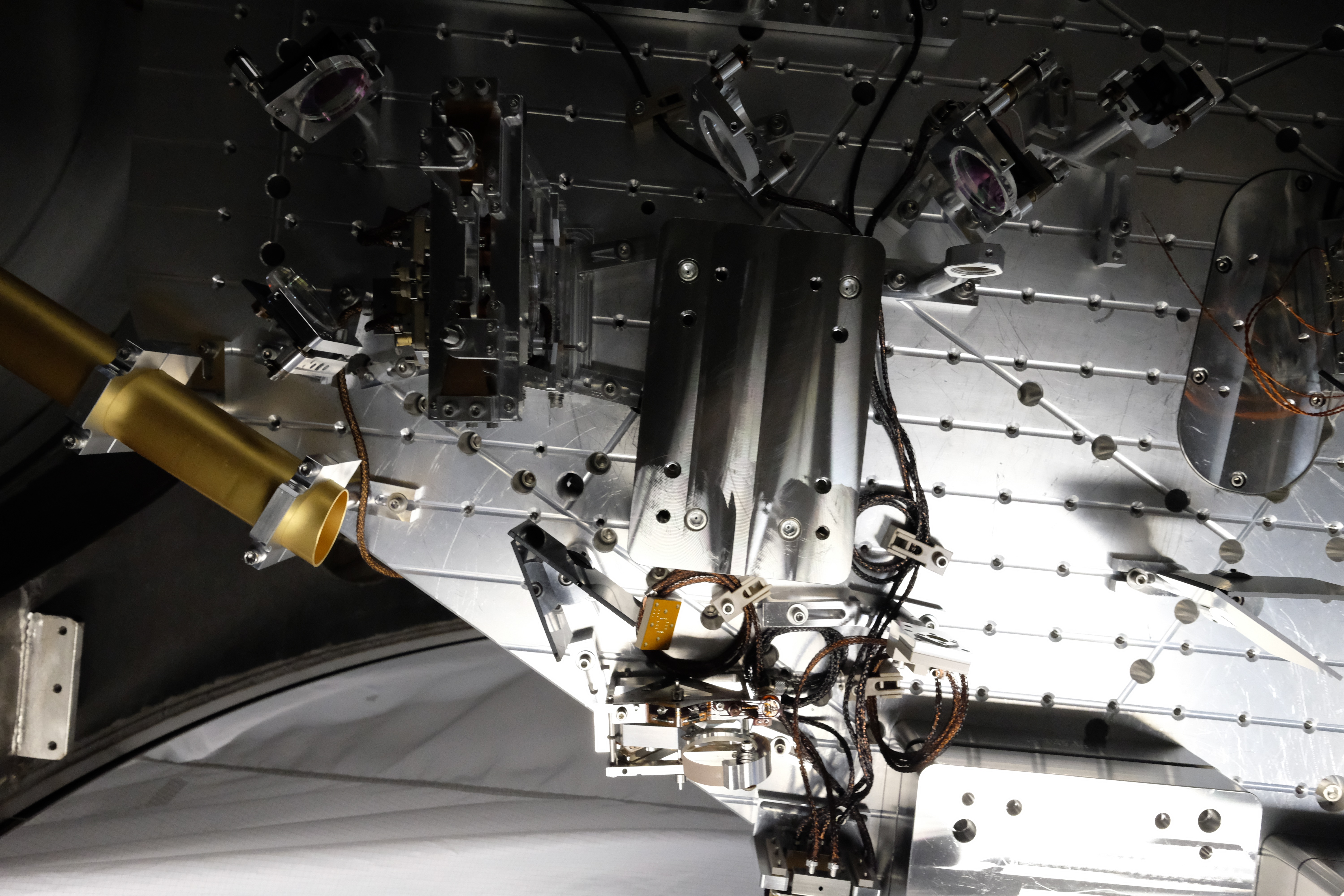
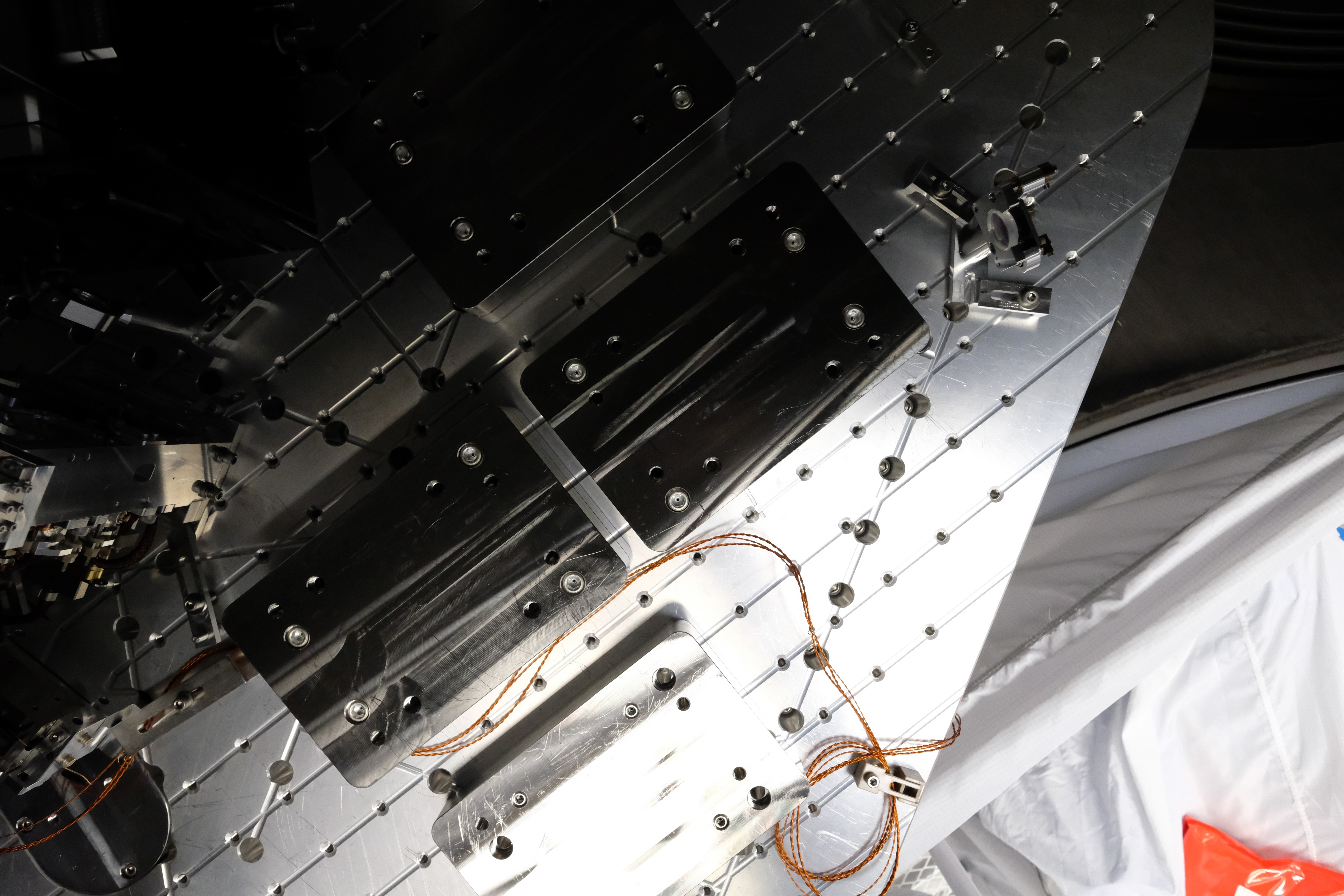
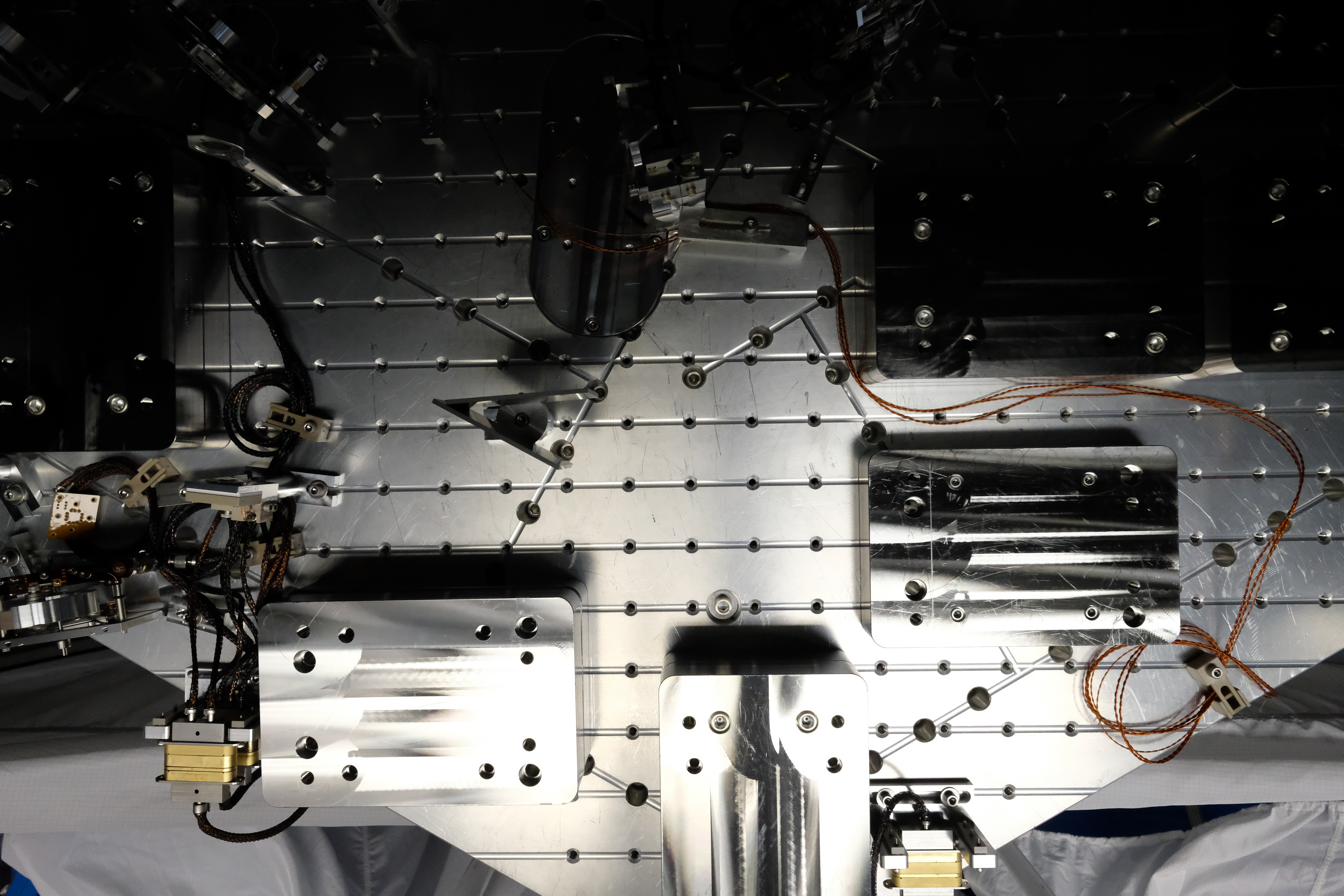
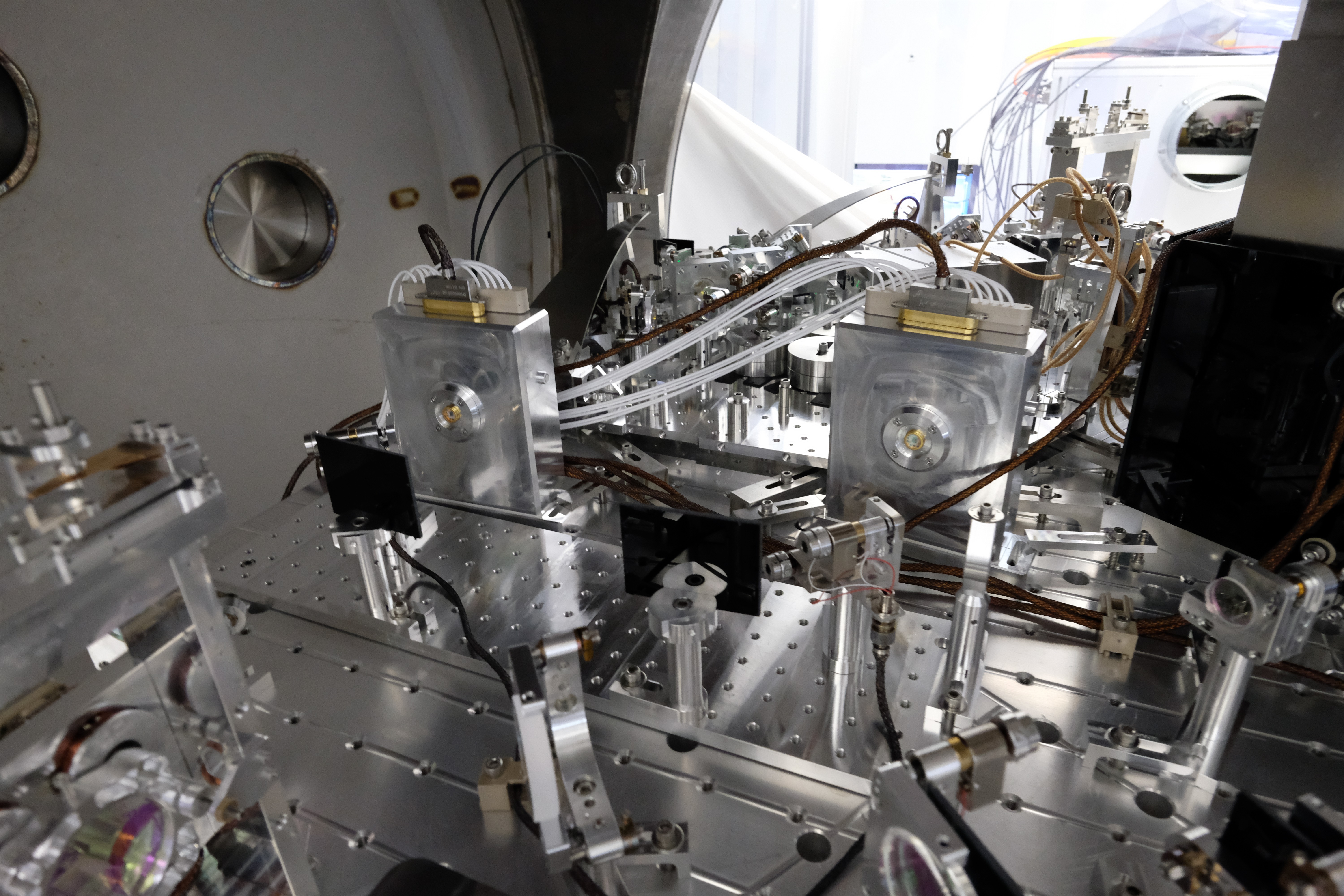
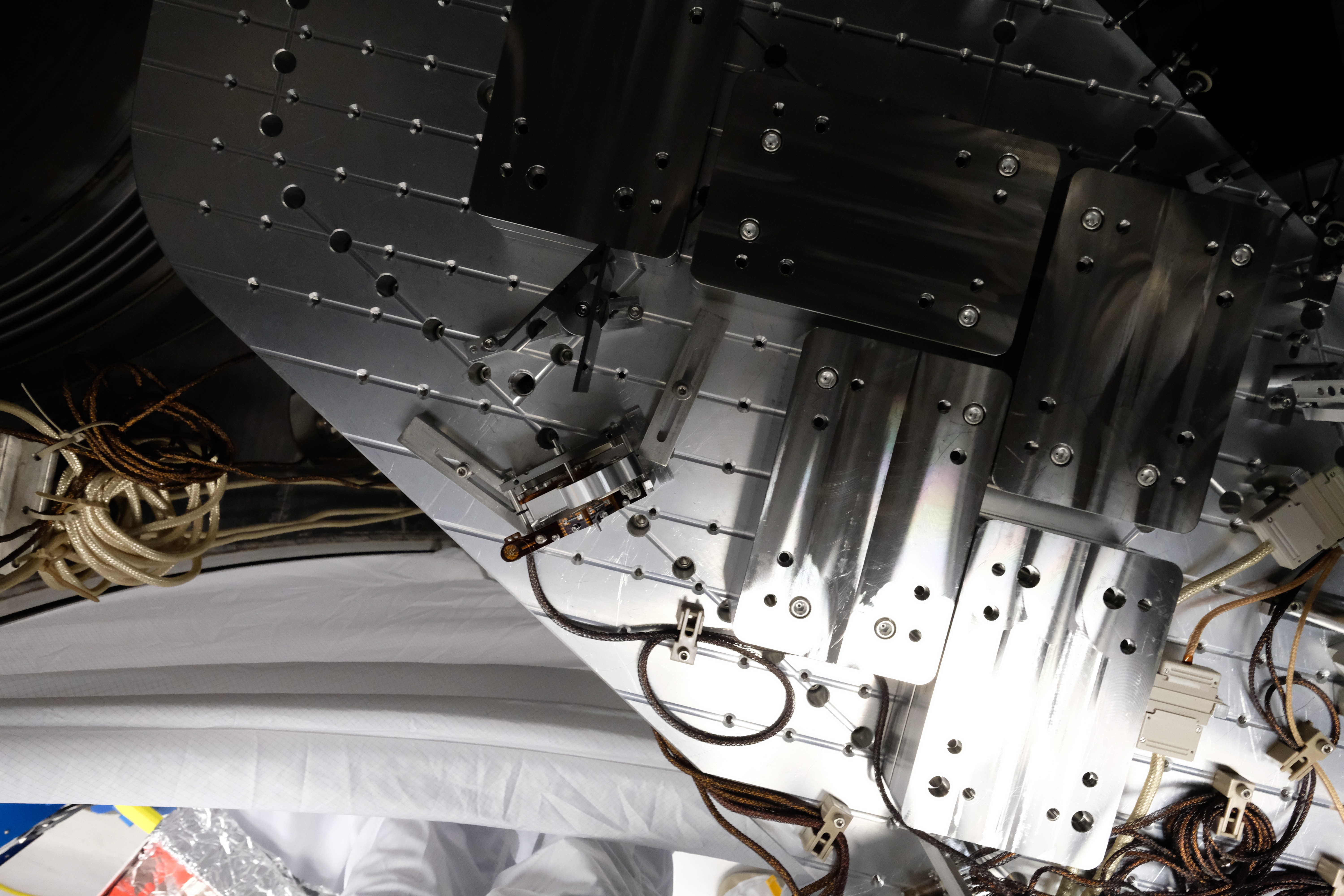
The new panels were installed on the TCS CO2 tables along with the new light pipe clamps and flange. Unfortunately, this design leaves a small gap between the D1600112 jaw plate and the flange, as seen here:
 .
.
I propose using metalized duct tape to seal the various gaps from the table. On CO2 X the T connectors had broken while trying to disconnect the tubing and was replaced. Also attached are photos of the IR sensor in place on the viewport, and the "strain-relief" connection on the laser power cable.


Also, CO2 Y chiller was taken out of RS-232 serial communication mode so I could manually turn it on to purge the air and refill the lost water from disconnecting the tubing. It wouldn't allow itself to be turned on otherwise. It should be able to be switched back without any issues.
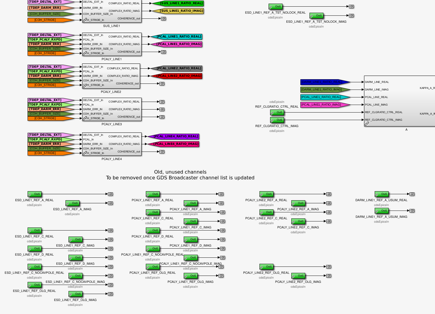
I rediscovered some old, unused channels in the CAL-CS model for calculating time varying parameters that are deprecated (see attached screenshot). As a reminder, we have updated the way time varying parameters are calculated (see T1500377 and, more recently, T1700106). During O2, we implemented SRC detuning tracking using a low frequency Pcal line, and at that point, the CAL-CS model was updated. We should plan to remove these at some point in the not-too-distant-future. An FRS ticket will be filed.
I wanted a quick first guess of new gains to use for the RF locking signals, so that we know roughly where to start when trying to lock DRMI, since the drive levels are slightly different with the new EOM. I'm using Koji's measured values from alog 41435. Note that the drive levels are slightly different now, since the EOM drivers have been moved to outside the PSL enclosure (alog 41852), but they're pretty similar. Our final gains will of course be set by measuring the loops, so this small discrepancy in the first round guess shouldn't really matter.
The amplitude of a PDH signal is proportional to J_0(Gamma)*J_1(Gamma), where J_n() is the Bessel function, and Gamma is the modulation depth in radians (see, for example, P1500001 appendix B for a derivation). The ratio that we will want to apply to the old gains will be:
ratio = ( J_0(Gamma_old) * J_1(Gamma_old) ) / ( J_0(Gamma_new) * J_1(Gamma_new) ).
For the 45 MHz channels (Gamma_old = 0.287, Gamma_new = 0.197), the ratio will be 1.43. For the 9 MHz channels (Gamma_old = 0.187, Gamma_new = 0.210) the ratio will be 0.89.
With the change out of the RF combiner for 45 MHz and 24 MHz (alog 41889), we now have a slighly higher modulation index for the 45 MHz signals. Now Gamma_45MHz is 0.259, rather than 0.197. This new value is much closer to the old EOM / RF driver combination from O2 of 0.287.
This means that the ratio defined in the above entry for 45 MHz is now 1.10.
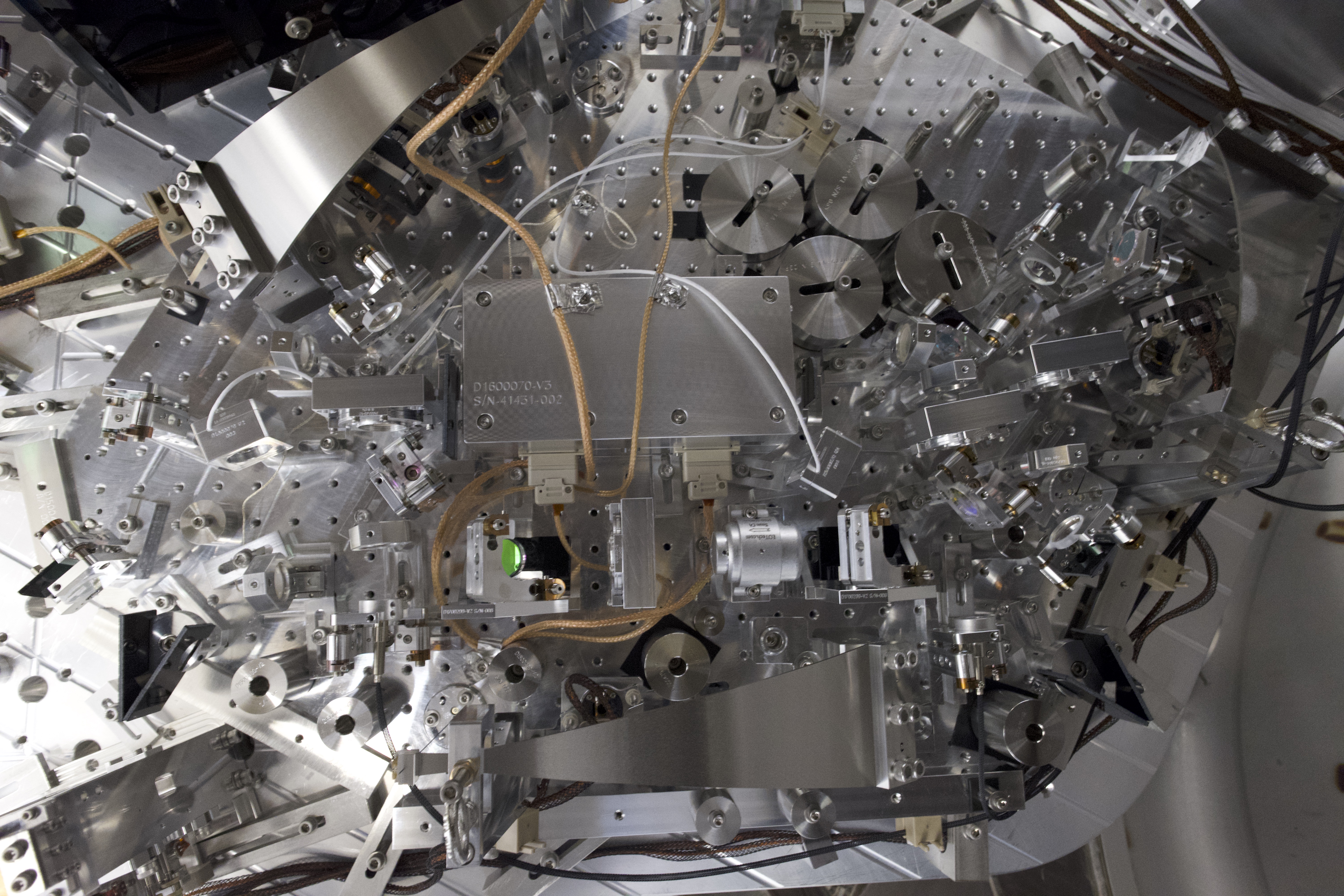
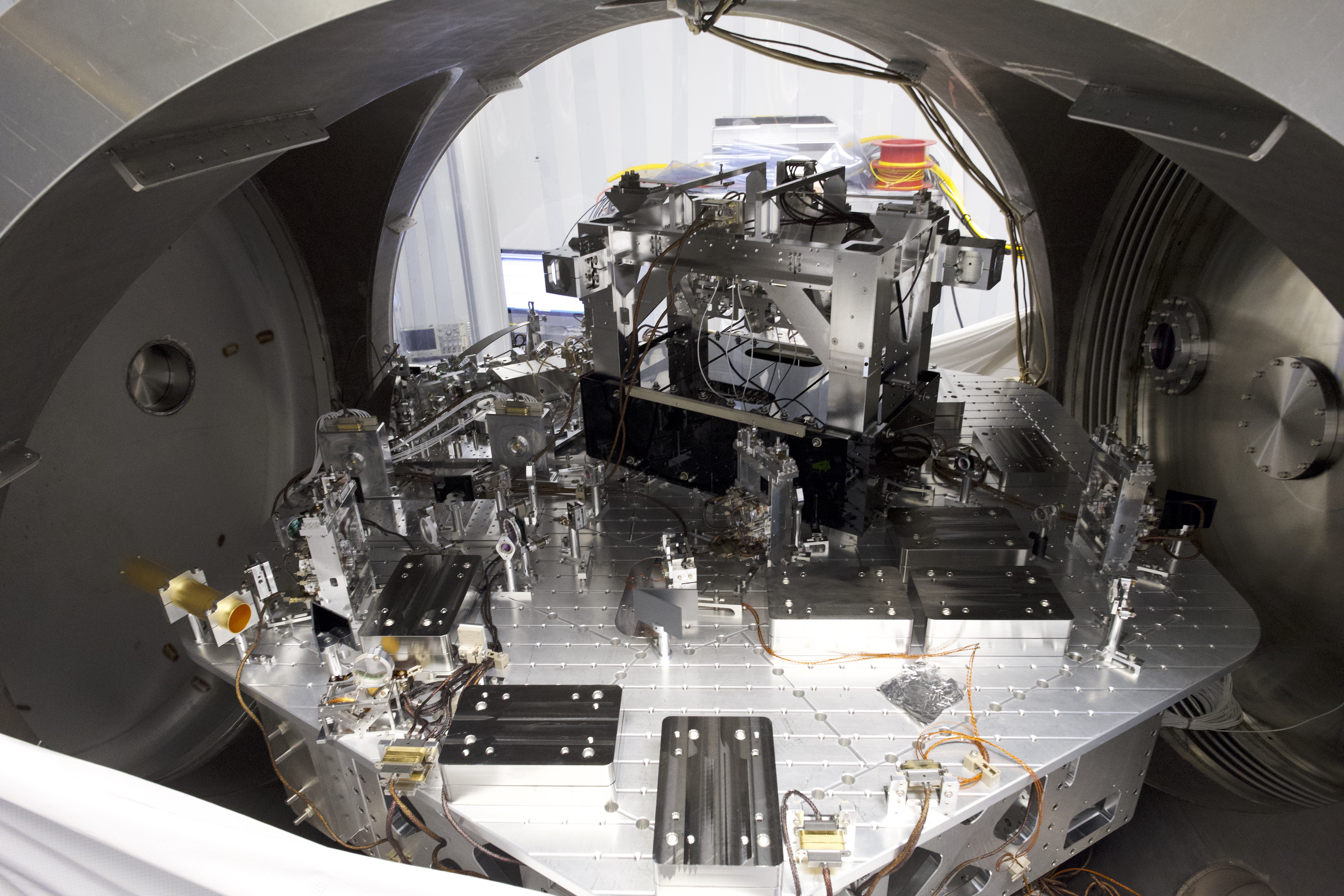
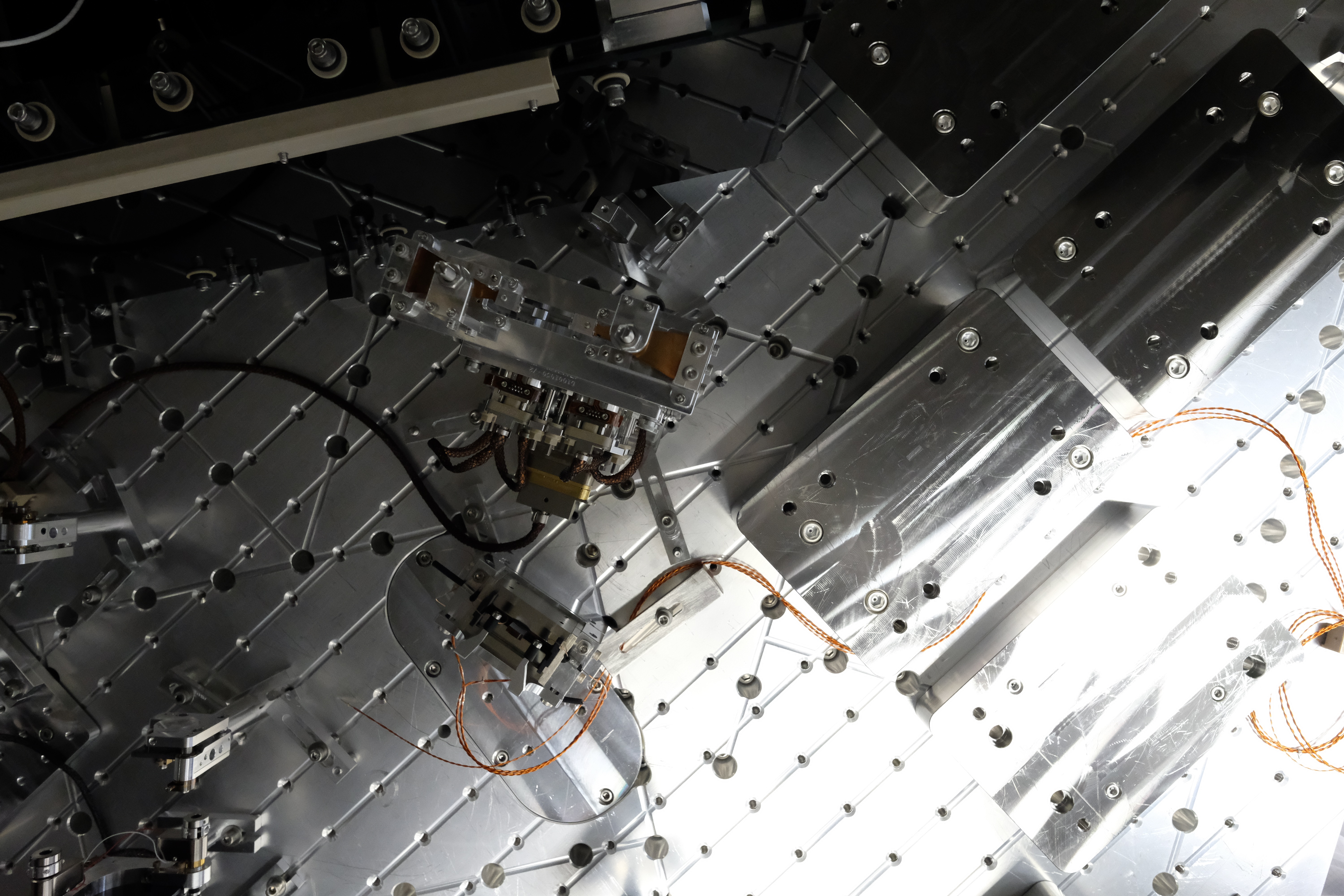
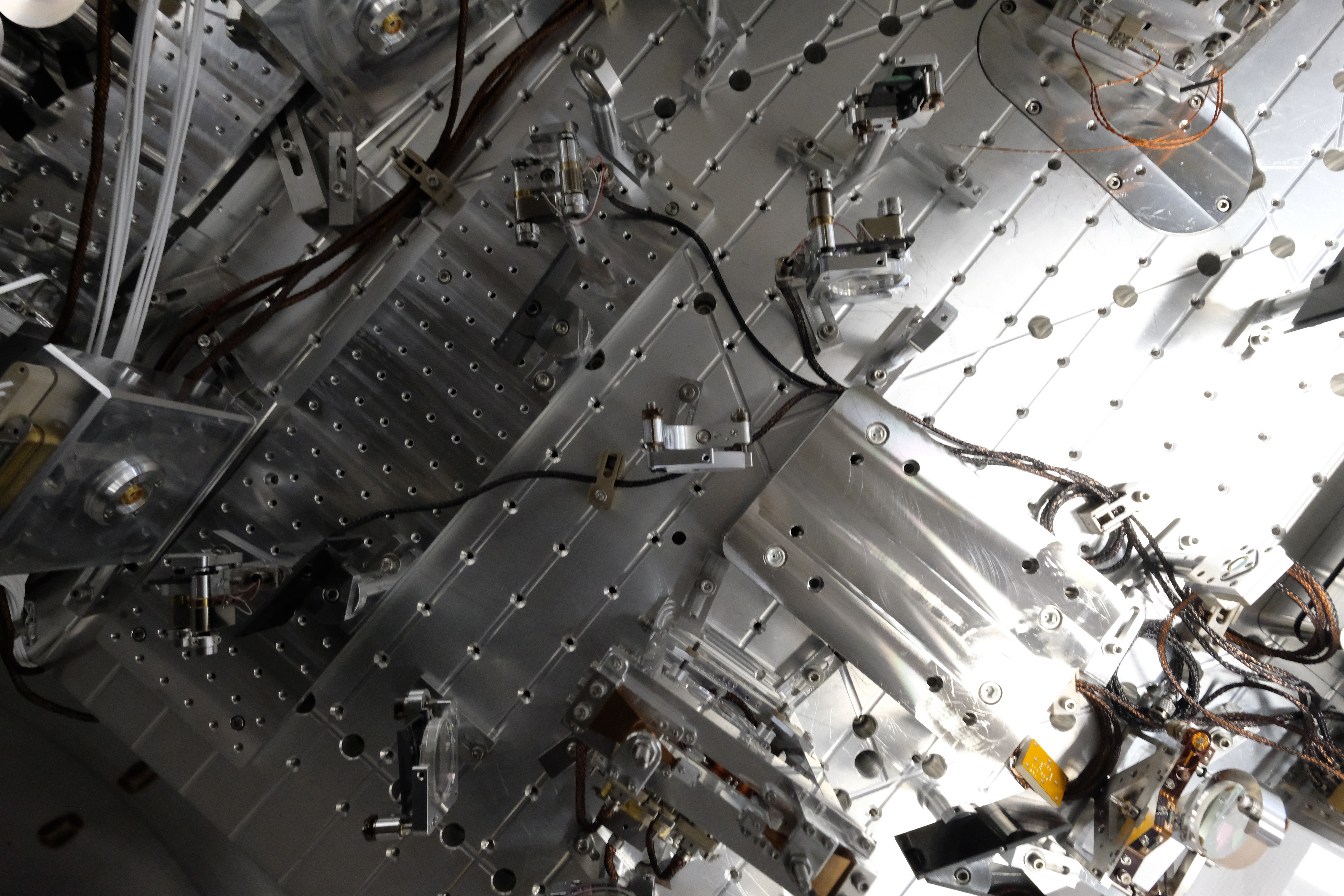
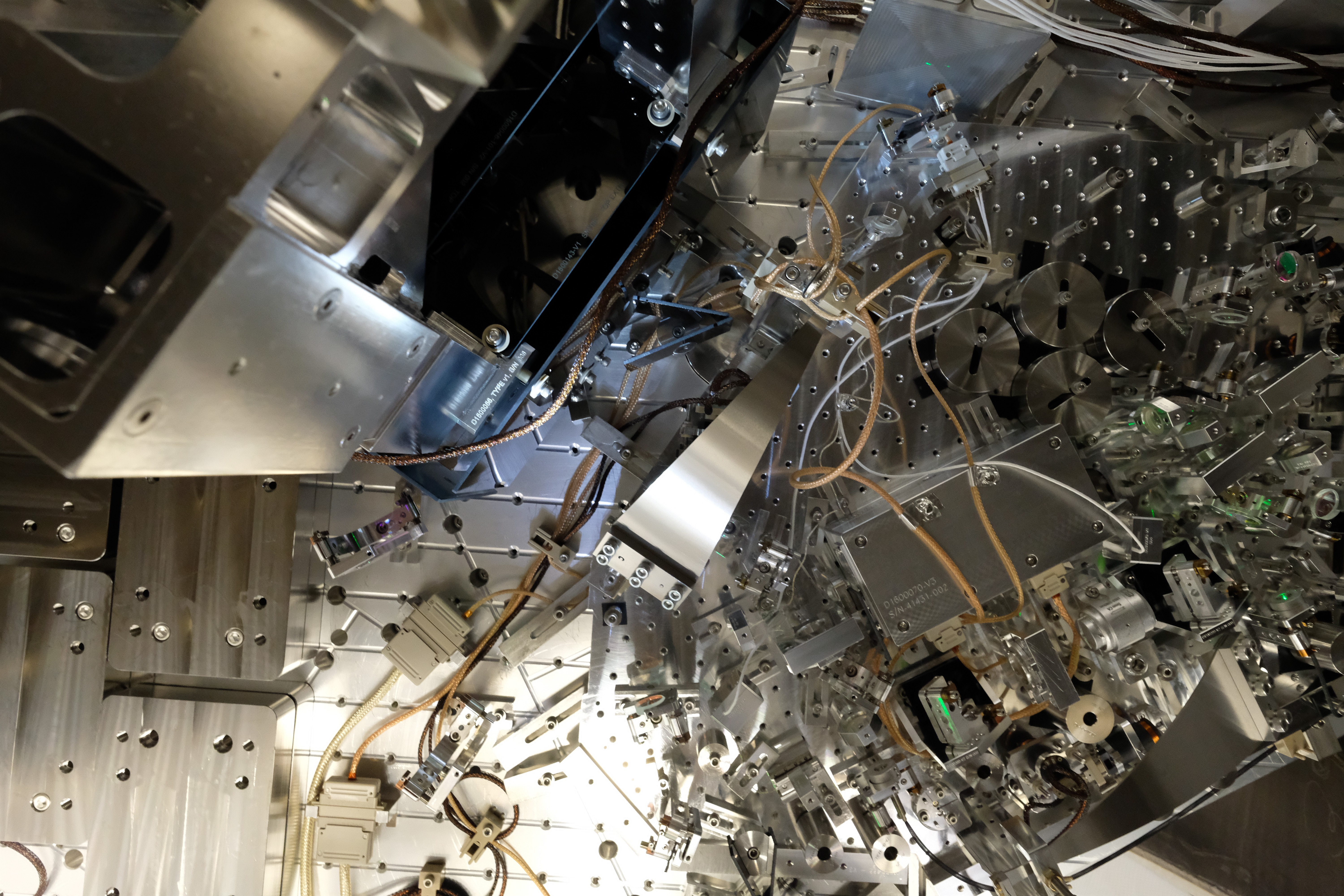
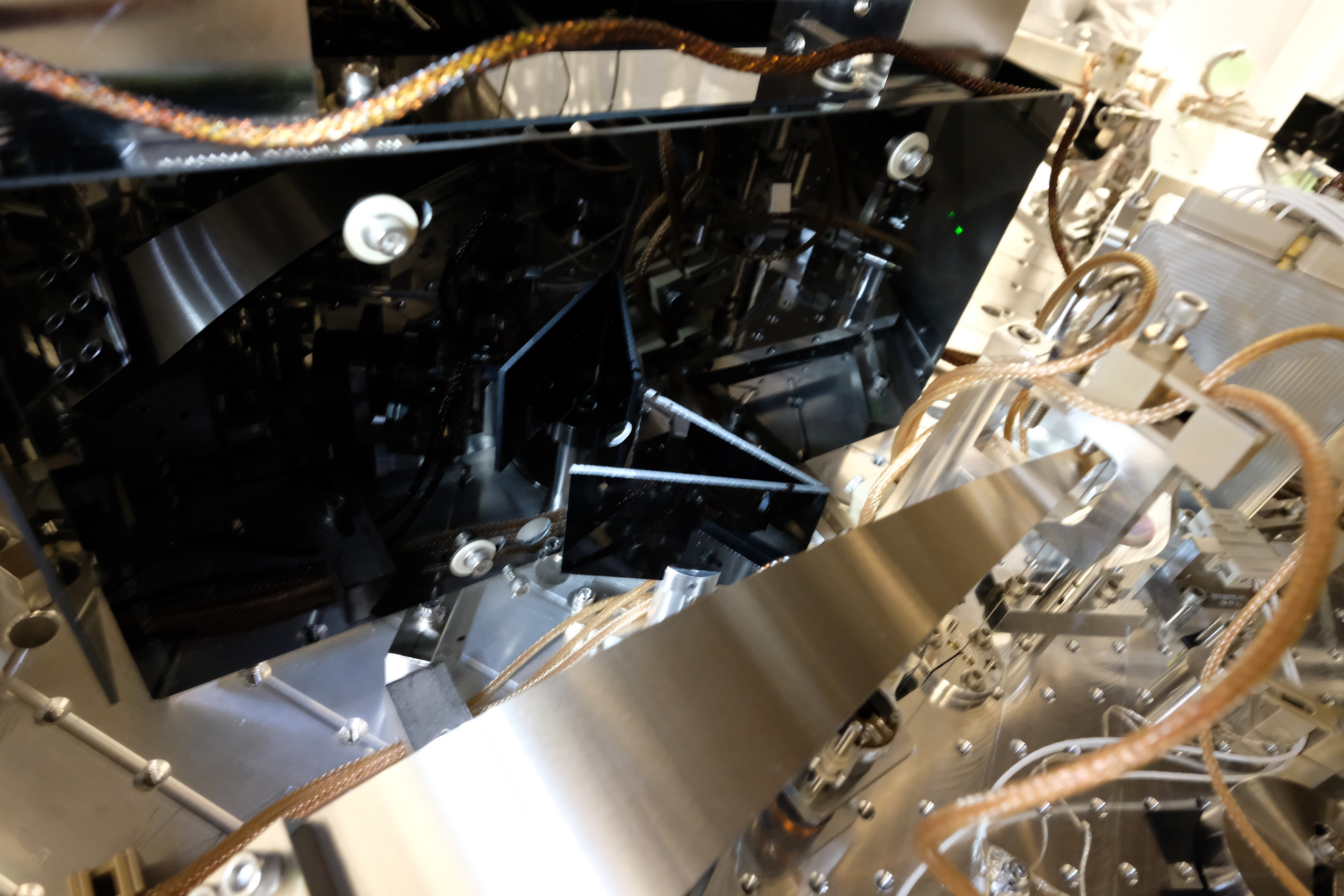
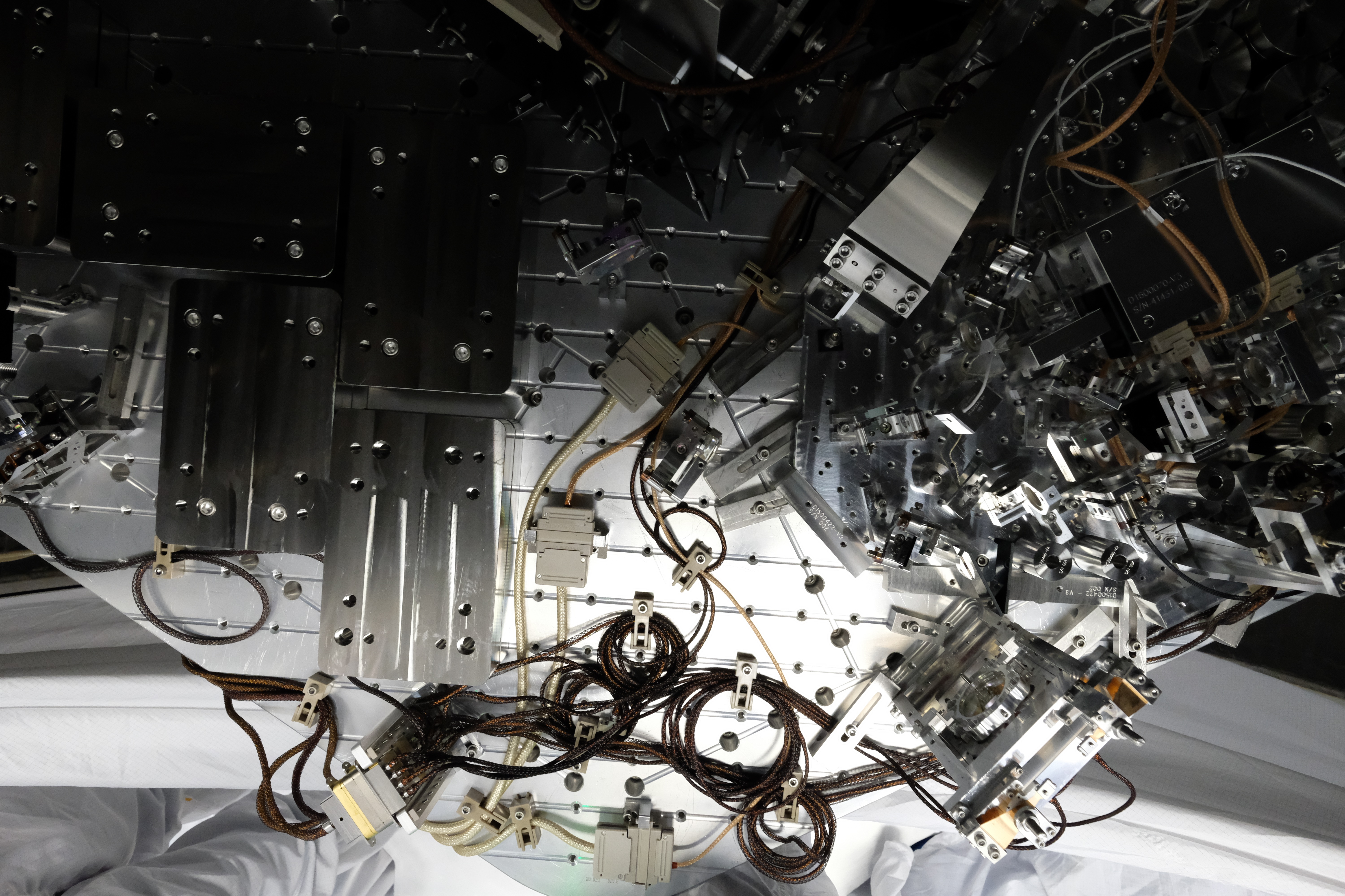
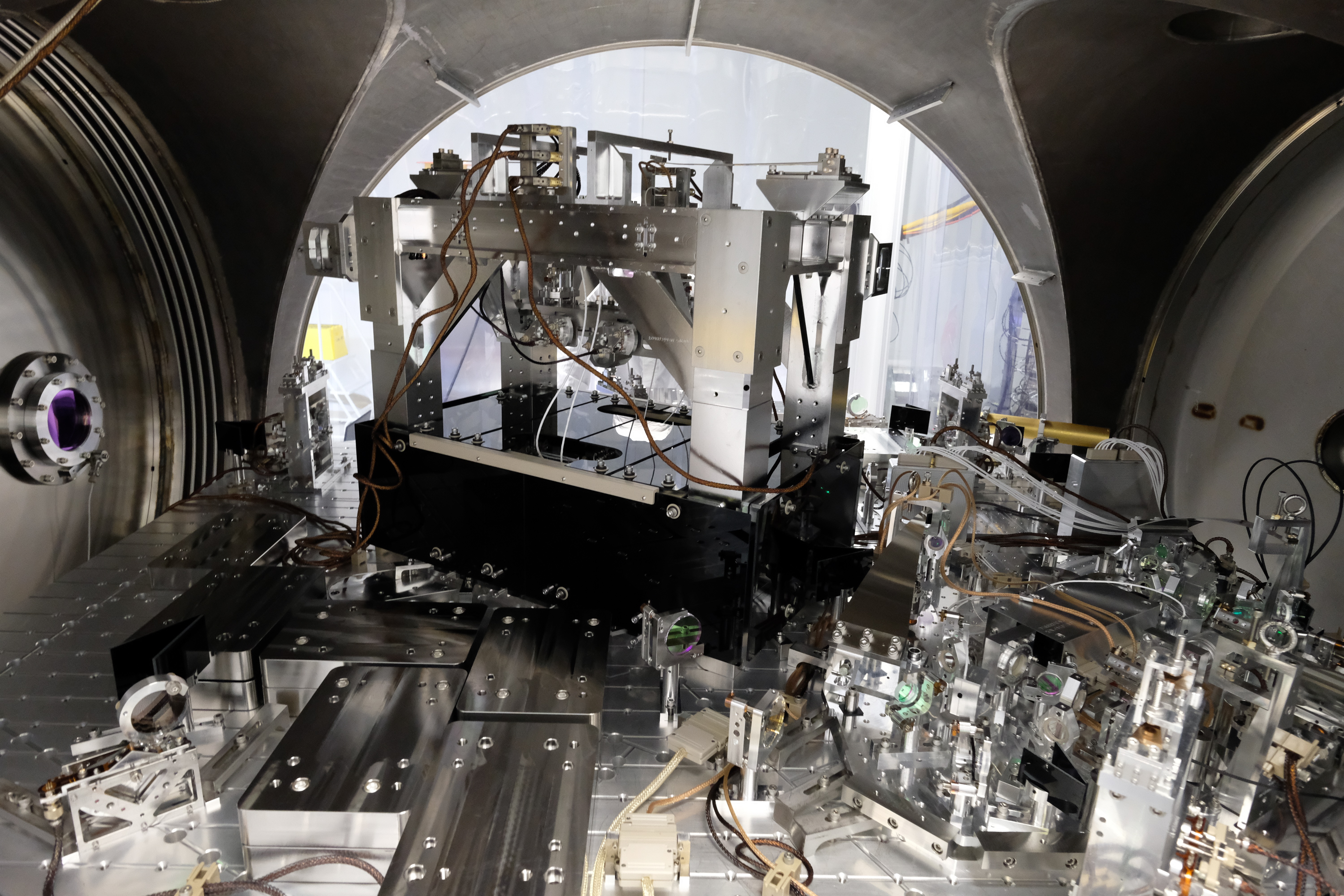
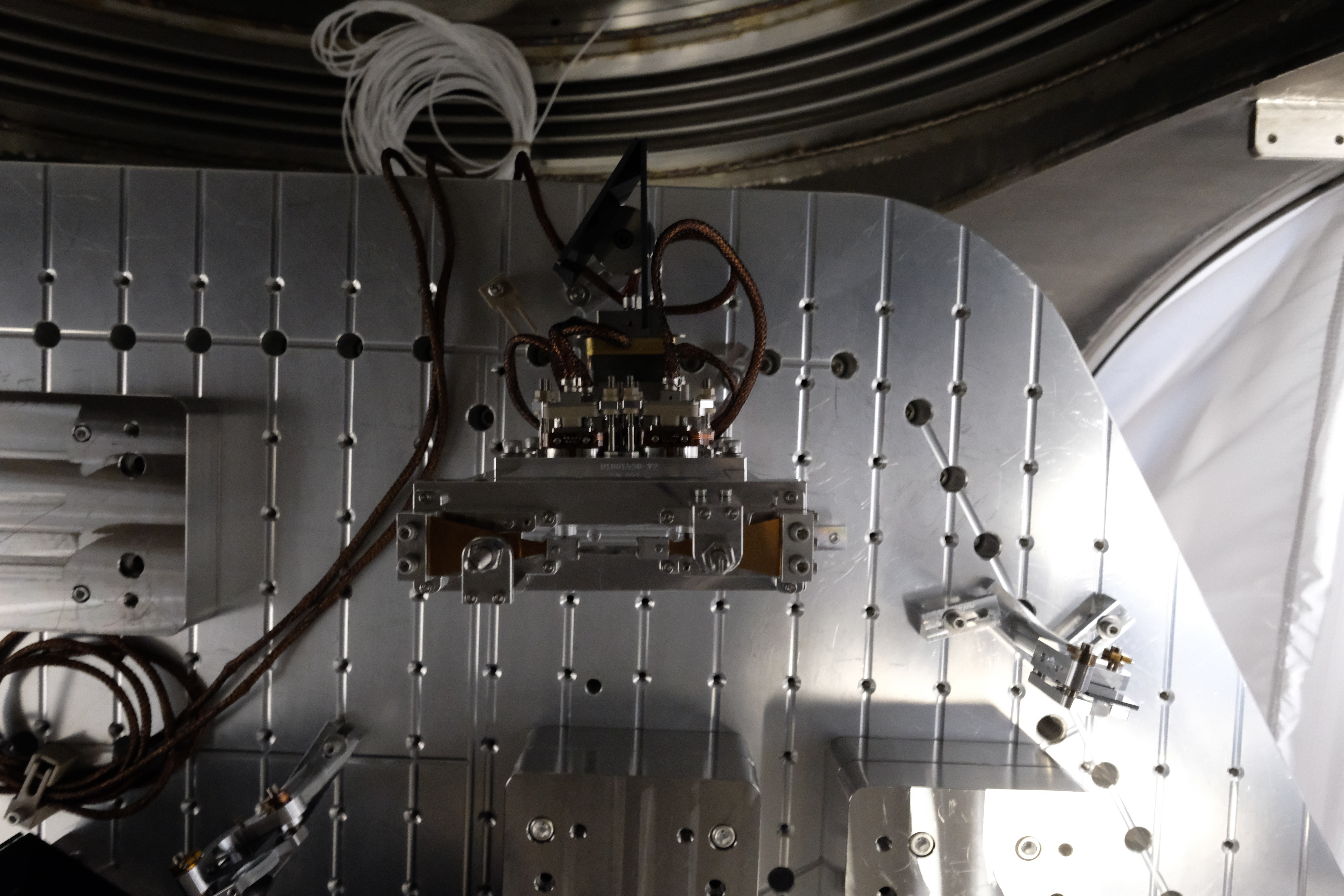
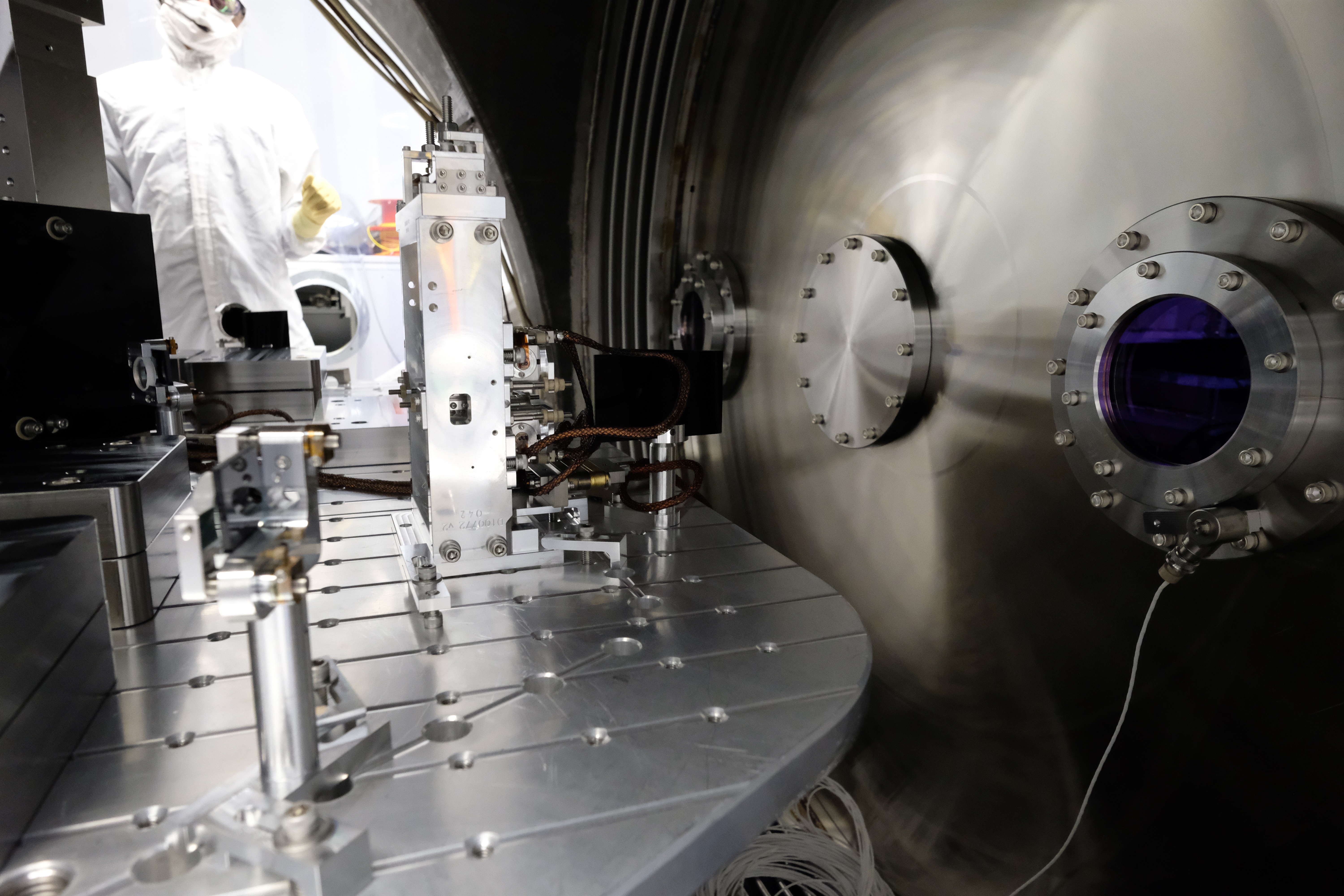
Here I attached some of the overhead shots of HAM6 table just before we closed out last time. Note that the quality of OPO overhead shot (with green light input) wasn't the best last time so I attached a better one from April 12th (no green light, first photo) when we were aligning the beam to the PSL. Overhead shot of OMC side of the table also came from April 12th (second photo). The rest of the photos were taken on April 26th.
While going through the photos I noticed a stray green beam hitting the back of a diode box (ASC DCPD?) and the OMC glass shroud. These photos are 6th and 7th from the right.
STS
2018-05-07 13:21:57.355505
There are 2 STS proof masses out of range ( > 2.0 [V] )!
STS A DOF Y/V = -4.561 [V]
STS A DOF Z/W = 5.58 [V]

All other proof masses are within range ( < 2.0 [V] ):
STS A DOF X/U = -1.631 [V]
STS B DOF X/U = 0.183 [V]
STS B DOF Y/V = 0.917 [V]
STS B DOF Z/W = -0.462 [V]
STS C DOF X/U = 0.299 [V]
STS C DOF Y/V = -0.139 [V]
STS C DOF Z/W = 1.083 [V]
STS EX DOF X/U = -0.108 [V]
STS EX DOF Y/V = 0.446 [V]
STS EX DOF Z/W = 0.219 [V]
STS EY DOF X/U = 0.226 [V]
STS EY DOF Y/V = -0.035 [V]
STS EY DOF Z/W = 0.531 [V]
Assessment complete.


T240
Averaging Mass Centering channels for 10 [sec] ...
2018-05-07 13:27:56.363239

There are 19 T240 proof masses out of range ( > 0.3 [V] )!
ETMX T240 1 DOF Z/W = -0.414 [V]
ETMX T240 2 DOF Y/V = -0.575 [V]
ETMX T240 2 DOF Z/W = -0.723 [V]
ETMX T240 3 DOF Z/W = 0.403 [V]
ITMX T240 1 DOF X/U = -1.033 [V]
ITMX T240 2 DOF X/U = -0.374 [V]
ITMX T240 3 DOF X/U = -1.208 [V]
ITMY T240 1 DOF X/U = -0.363 [V]
ITMY T240 1 DOF Y/V = -0.502 [V]
ITMY T240 1 DOF Z/W = -0.383 [V]
ITMY T240 2 DOF Z/W = -0.582 [V]
ITMY T240 3 DOF X/U = -1.121 [V]
ITMY T240 3 DOF Y/V = -0.307 [V]
ITMY T240 3 DOF Z/W = -1.553 [V]
BS T240 1 DOF X/U = -0.364 [V]
BS T240 1 DOF Y/V = -0.432 [V]
BS T240 2 DOF Z/W = -0.417 [V]
BS T240 3 DOF Y/V = -0.47 [V]
BS T240 3 DOF Z/W = -0.638 [V]


All other proof masses are within range ( < 0.3 [V] ):
ETMX T240 1 DOF X/U = -0.164 [V]
ETMX T240 1 DOF Y/V = 0.242 [V]
ETMX T240 2 DOF X/U = -0.216 [V]
ETMX T240 3 DOF X/U = -0.17 [V]
ETMX T240 3 DOF Y/V = 0.03 [V]
ETMY T240 1 DOF X/U = -0.063 [V]
ETMY T240 1 DOF Y/V = 0.175 [V]
ETMY T240 1 DOF Z/W = -0.123 [V]
ETMY T240 2 DOF X/U = 0.013 [V]
ETMY T240 2 DOF Y/V = -0.135 [V]
ETMY T240 2 DOF Z/W = -0.012 [V]
ETMY T240 3 DOF X/U = -0.141 [V]
ETMY T240 3 DOF Y/V = -0.066 [V]
ETMY T240 3 DOF Z/W = 0.142 [V]
ITMX T240 1 DOF Y/V = -0.261 [V]
ITMX T240 1 DOF Z/W = -0.227 [V]
ITMX T240 2 DOF Y/V = -0.262 [V]
ITMX T240 2 DOF Z/W = -0.16 [V]
ITMX T240 3 DOF Y/V = -0.098 [V]
ITMX T240 3 DOF Z/W = -0.209 [V]
ITMY T240 2 DOF X/U = -0.108 [V]
ITMY T240 2 DOF Y/V = -0.045 [V]
BS T240 1 DOF Z/W = -0.018 [V]
BS T240 2 DOF X/U = -0.232 [V]
BS T240 2 DOF Y/V = 0.088 [V]
BS T240 3 DOF X/U = -0.173 [V]
Assessment complete.

   Chamber closeout and Quad install work is underway at this time.
Laser Status:
SysStat is good
Front End Power is -0.0078W (should be around 30 W)
HPO Output Power is 0.7958W
Front End Watch is GREEN
HPO Watch is RED

PMC:
It has been locked 1 days, 0 hr 52 minutes (should be days/weeks)
Reflected power = 16.42Watts
Transmitted power = 51.77Watts
PowerSum = 68.18Watts.

FSS:
It has been locked for 2 days 19 hr and 40 min (should be days/weeks)
TPD[V] = 1.838V (min 0.9V)

ISS:
The diffracted power is around 1.8% (should be 3-5%)
Last saturation event was 0 days 1 hours and 6 minutes ago (should be days/weeks)

Possible Issues:
Front End Power is Low
ISS diffracted power is Low
LRA out of range, see SYSSTAT.adl
The attached photo shows to damage to the connector/back plane. Fil is pretty confident that we can repair. The problem is the lifting point on this door--rather than a strap with a large opening for shackles, it is a flange with a smallish hole. This requires the door crew to have more elements in the lift rig--maybe we can improve that..it's only money. Still, we should maybe look to moving these CPS racks to a different spot.
Further, many of the cables above the west side door on BSC3 (ITMX) are vulnerable to damage depending on how high this cable tray is being lifted--the cable tray is not too far from the feedthrus and cables are going thru the tray mesh or are on top of the tray so this also puts the feedthrus at risk. I've filed FRS 10557 to mitigate this risk as much as possible.
Meanwhile--The ISI operates normally and sensor spectra look good. St2 H3 CPS had some higher noise so that corner CPS was power cycled and the St2 H3 gauge board was un & re seated a few times; that action cleared the noise.
FRS 10551, WP 7531

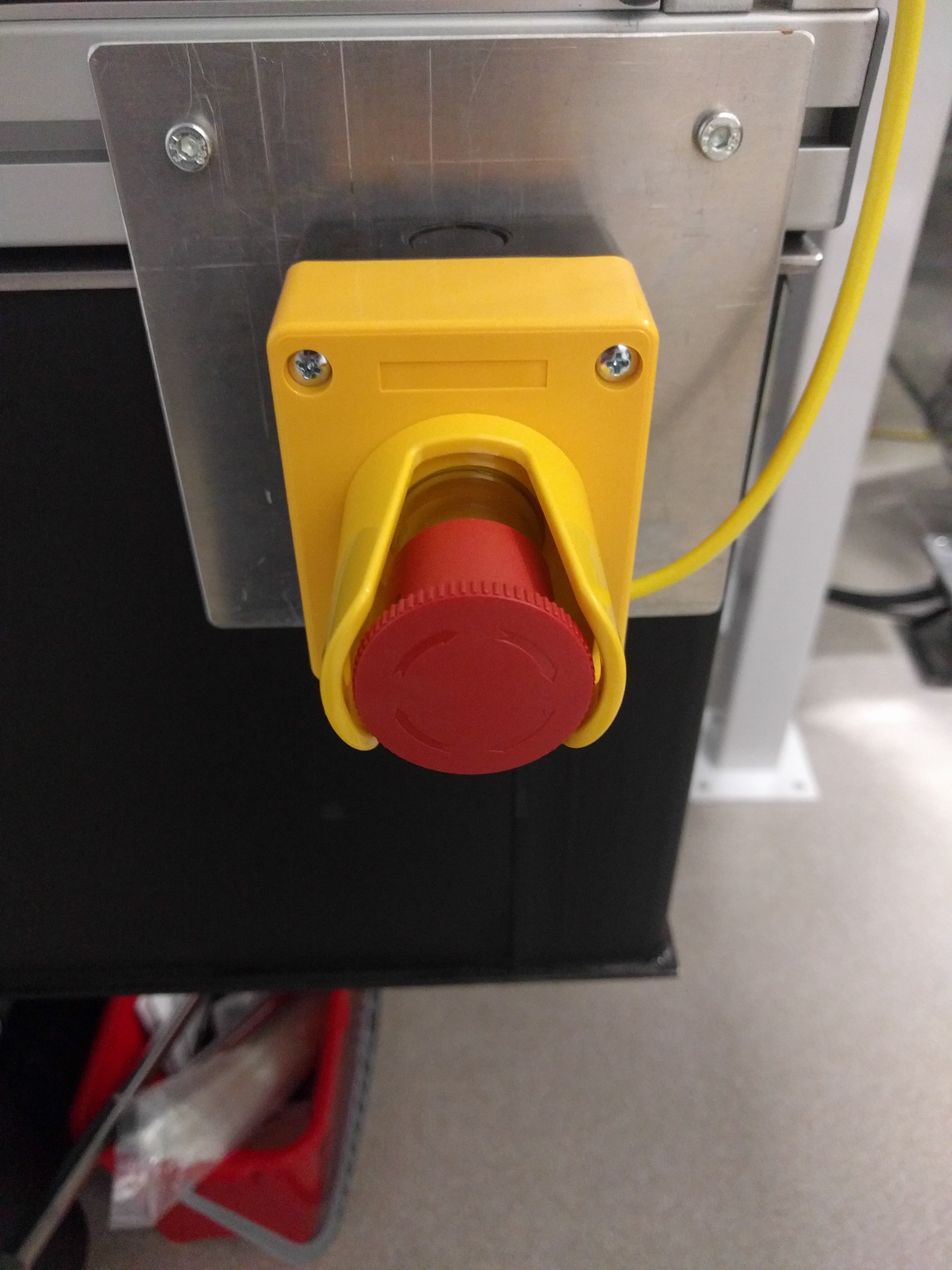
To avoid the E-stop buttons from accidently being engaged a cover was added to the E-stop buttons at EY.

Reinstalled access control network switch at EY. Unit lost communication sometime las week. The SFP transceiver was replaced. Link lights show communication with network switch and newly installed cameras.
Used a FieldFox Handheld RF Analyzer to look at the EY ESD in-vacuum cabling. Test description can be found in T1800199. Found similar cable lengths as described in the document for LLO EY in-vacuum cable lengths.
LR - 39.51 ft
UR - 39.97 ft
UL - 39.94 ft
LL - 40.24 ft
Bias - 42.63 ft
Lengths are at the feedthrough using a 3.5 ft jumper cable.
Ronaldas, Sheila
I have restructured previously used noise budget code (git repo, see /restructured_nb folder). This way it is easier to add other noises and debug the code.
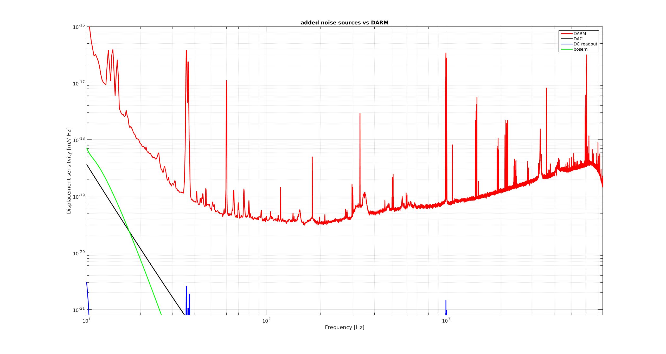
Afterwards we added additional noise sources:
1) actuator DAC noise - DAC noise from the test mass PUM based on the model in G1100968
2) DC readout quadratic term - see an alog DC readout quadratic term
3) osem sensors noise - noise from the top mass damping to the quad suspensions
4) thermal noise (updated to the most current GWINC version)
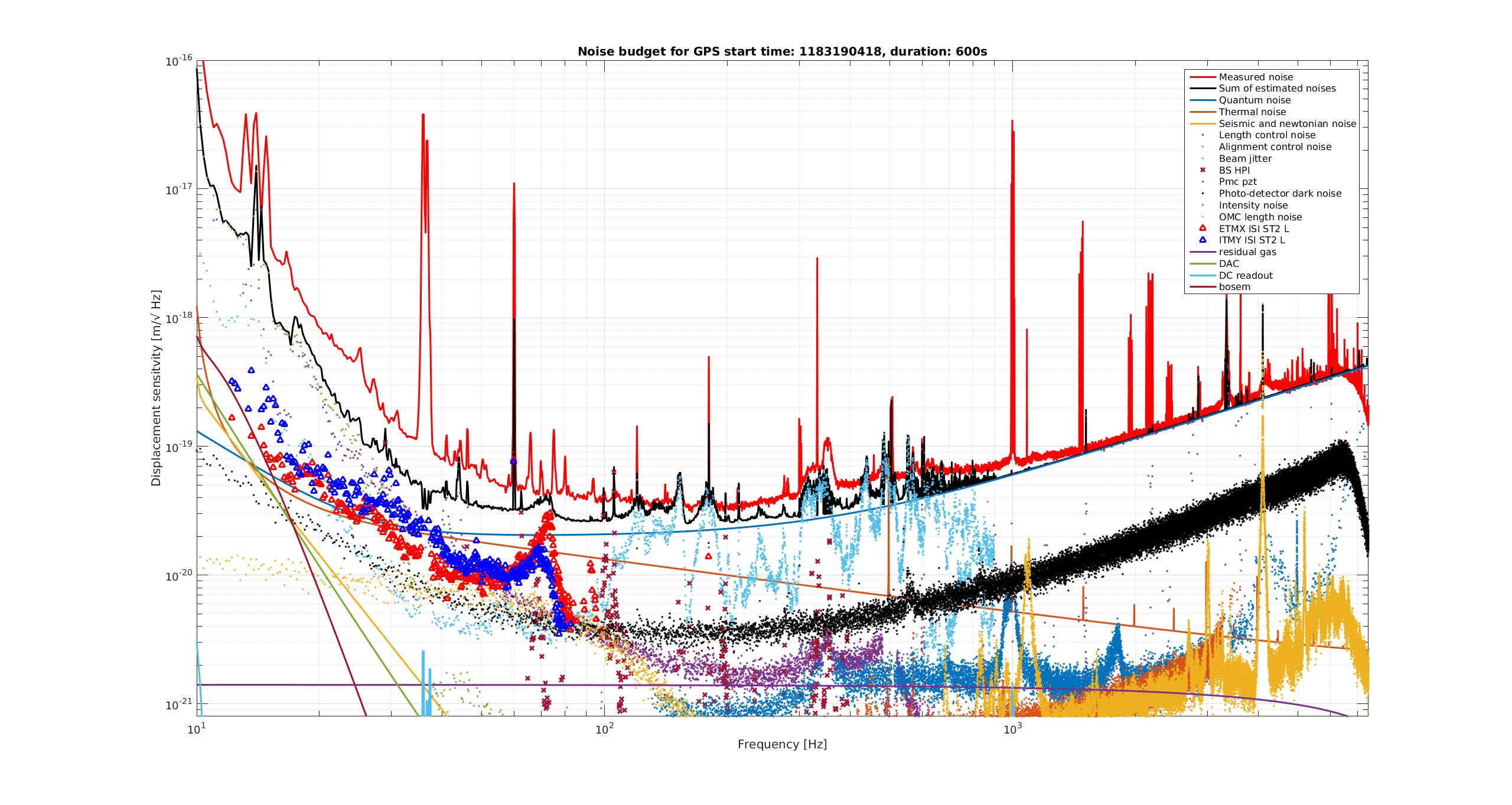
Attached plots show a contribution from recently added noises (recent_contribution_NB.jpg) and an example of total noise budget (noise_budget.jpg). Plots are made using July 4th 2017 data, a lock before the earthquake that increased LHO noise.
Currently we are working on two noises:
1) residual gas in vacuum: squeezed film damping noise and residual gas in arms.
2) coherent noise: a coherence based projection of jitter from the bullseye sensor upstream of the PMC, which was contributing to the DARM noise from 30Hz-1 kHz in this lock stretch
Thanks Jeff for suspension quadmodel and controls design summary table - that saved tons of time!
Also, a note: let me or Sheila know if you think there is a noise source that should be in this noise budget.
Added 50ml water to Crystal chiller. Added 100ml water to Diode chiller. Both Crystal and Diode filters are clean and clear. No debris noted in either filter.
JasonO, PeterK, RickS
Last Friday evening, we left the PSL in a state that will hopefully be sufficient for commissioning-related activities this week, during which all three of us will be on travel.
The full output power, 65-70 W, is directed into the PMC, with about 52 W transmitted.
The PMC output is directed to the beam dump directly downstream of the PMC. Thus, the half-wave plate at the PMC output will have to be rotated manually to send the PSL output beam through the EOM and into the MC.
Note that the EOM mount is quite unstable. The springs in the 5-axis NewFocus stage can accommodate the EOM weight if all forces are downward. But with the new RF cables (and maybe even with the old RF cables) the stability of this mount is marginal. Attention to EOM beam centering and mount stability (cable strain relief, etc.) should be given when directing the PMC output through the EOM.
The PMC and FSS loops are performing nominally, but the ISS loop is disabled (AOM not yet installed).
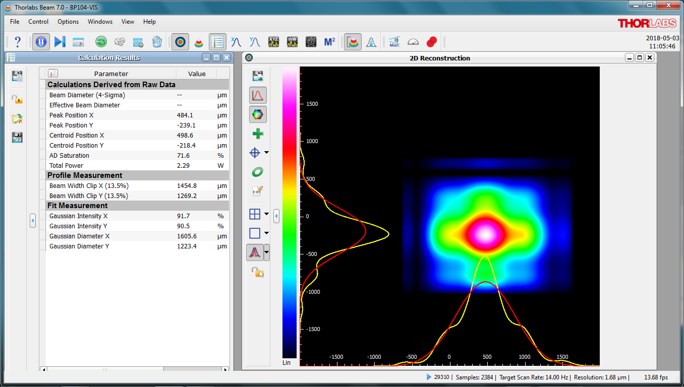
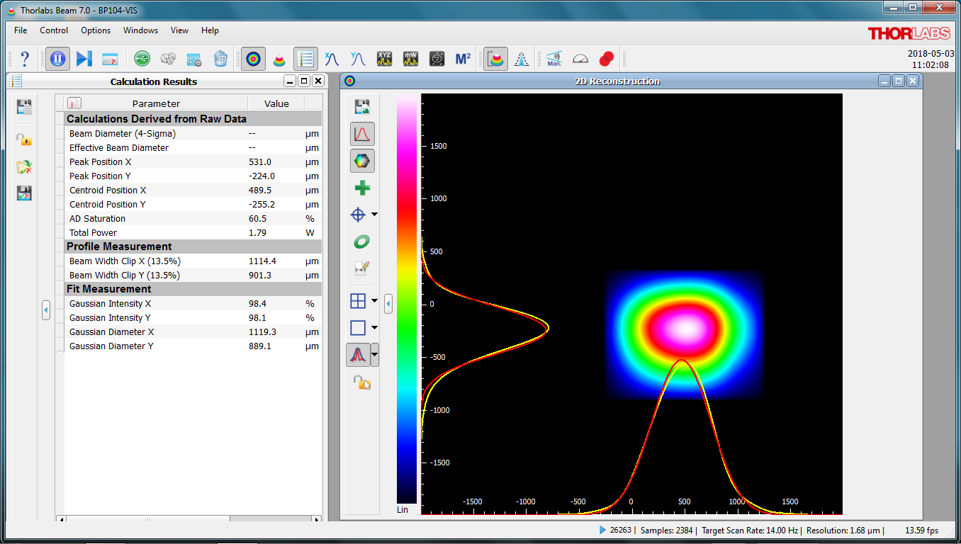
After the past two weeks of working with the 70-W amplifier, we think we finally have a good understanding of the modematching to the PMC. The PMC visibility is currently about 82%. This is limited by a "pedestal" that is apparently due to either a Front End output beam with this pedestal or to having too small a beam entering the 70 W amplifier. When an iris is installed upstream of the PMC and closed to the point that 10-15 W is occluded by the aperture, the PMC visibility increases to about 92-94%. This is corroborated by the Beam Scan data (see attached BeamScan data and images).
When time allows, we will scrutinize the Front End output beam (apparently this was not optimized after swapping out the NPRO some time ago). Then, after consulting with Mike Frede et al. at NeoLase, we will re-visit the modematching into the 70 W amplifier, then the modematching into the PMC.
1050 hrs. local -> Leaving site now.
0555 - 0620 hrs. local -> Briefly in to make manual adjustments @ CP4 RGA and to shut down the Corner Station's purge-air supply.
0620 hrs. local -> Leaving site now.
Fil Peter Rick Jason Daniel
We moved the EOM drivers from under the PSL table to the bottom of the PSL-R2 rack. The setup itself is still the same until we get the RF combiner/amplifier. Before connecting back to the EOM, we remeasured the RF power using the same settings of 23.4 dBm and 27.0 dBm for 9 and 45 MHz, respectively. As a comparison, we also give the numbers from Koji's alog 41435.
| Frequency | old alog 41435 | @rack PSL-R2 | @ EOM | Cable loss | Difference |
| 9.1 MHz | 23.56 dBm | 23.49 dBm | 23.33 dBm | 0.16 dB | –0.07 dB |
| 24.07 MHz | 24.60 dBm | 25.33 dBm | 24.90 dBm | 0.43 dB | +0.30 dB |
| 45.5 MHz | 23.76 dBm | 23.84 dBm | 23.48 dBm | 0.36 dB | –0.28 dB |
| 118 MHz | 9.84 dBm | 10.22 dBm | 9.66 dBm | 0.56 dB | –0.18 dB |
The cable loss for the 24 MHz signal seems a little high and might be due to an imperfect VSWR. Otherwise, the RF levels are close, but the RF phases will have changed.
More details in T1800196.
ZM1 in-chamber cable between the feed through and the cable bracket on HAM6 was swapped, loop gone.
It was swapped and the ground loop of that part was fixed. But the new cable didn't have screws in DB25 to secure the connection, so we're transplanting the screws from the old cable to the new one.
ZM1 DB25-micro DB9 cable (that goes to the BOSEMs), disconnecting/reseating/shimming/tilting done, loop gone.
There was also some problem(s?) with ZM1 DB25 to micro DB9 cable. It's the same failure as the one reported for OM3 yesterday (https://alog.ligo-wa.caltech.edu/aLOG/index.php?callRep=41709). Jim tried to angle the connectors to clear the problem, which helped three of them but LR was persistent. He half-disconnected the micro DB such that no metal part of the back shell could possibly touch the aluminum BOSEM body/plate but there's still electrical connections to the pins, and the problem still persisted, which sounded like a problem of BOSEM itself. However, when we totally pulled the BOSEM from the TT cage and connected it back to the cable, we didn't see ground loop.
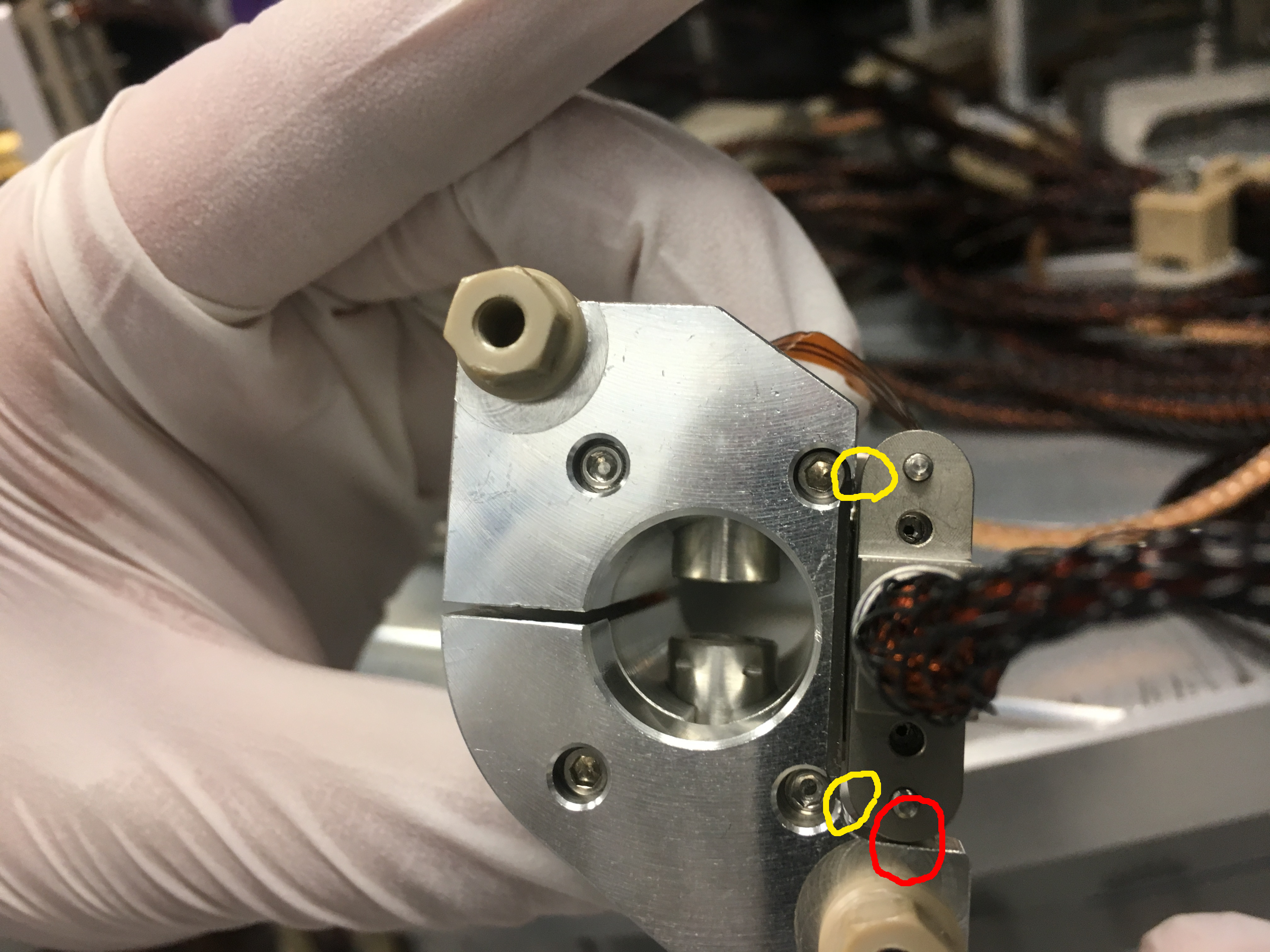
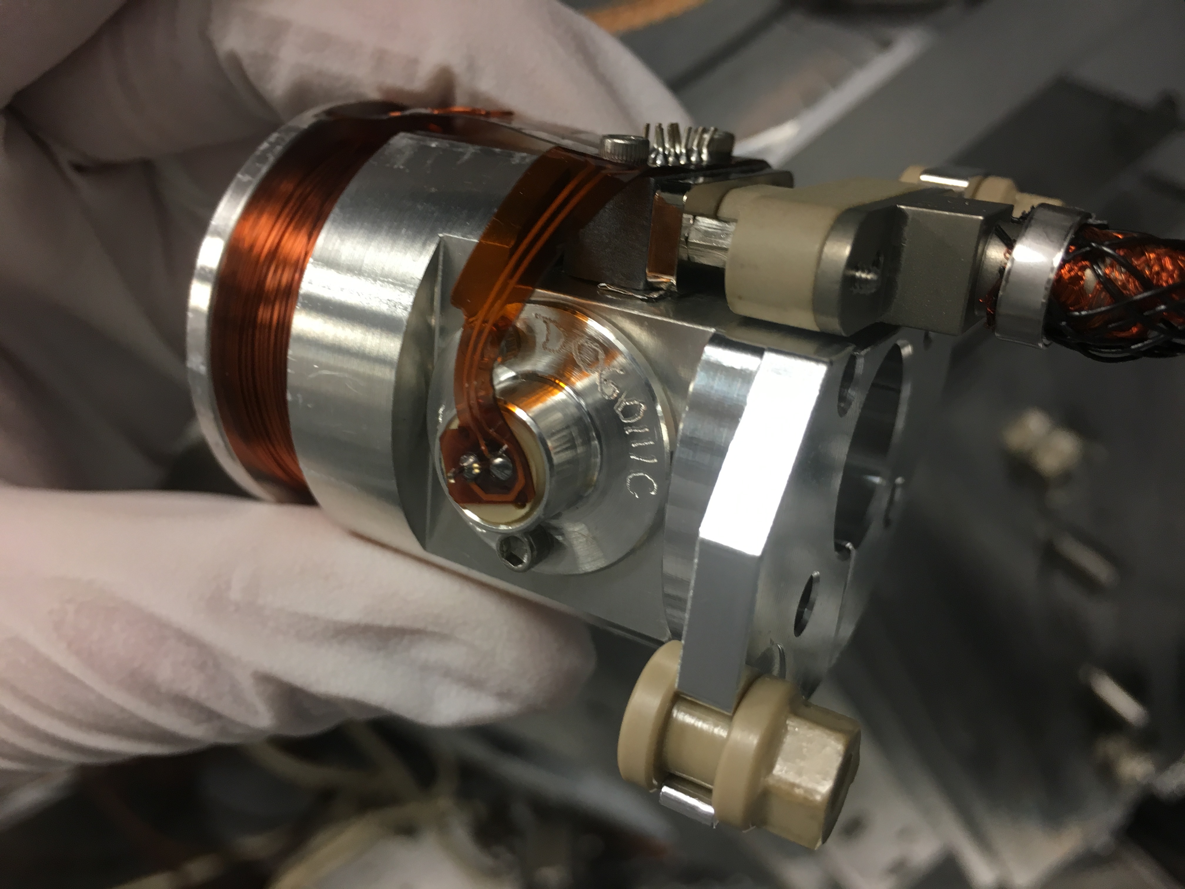
I inspected it and saw a tell-tale tiny gap between the back shell and the BOSEM/plate. As a preventative measure we performed foil-shimming-shell-tilting procedure explained in https://alog.ligo-wa.caltech.edu/aLOG/index.php?callRep=12346. First attachment shows "after" photo (there's no "before"), there are three potential short circuit points, two (circled in yellow) look much better, one (red) is actually better than before but I can only barely slip a sheet of foil through. The second attachment shows the foil used as a shim underneath the micro DB9 on the BOSEM body. It's really important that the cable side connector doesn't sit on this foil. The third one is an in-situ picture. Looks scary close but actually there's a gap. Suboptimal but this is as much as we can do.
OMC QPDs is left as is, nothing to fix.
After going back and forth between Koji and Rich, I'm convinced that this is a known symptom.

Ground loop checks were completed after in chamber cabling work.
SUS checked out good with the exception of OM3 (ISC_238).
ASC WFS cabling (ISC_255 & ISC_266) at rack side (DB15 connector) does not have pin 8 connected to shield. Shield tied to both pins 14 and 15.
Beam diverter cables (ISC_316 & ISC_317) at rack side (DB9) don't have pin 5 installed. Shield is tied to earth ground.
PZT cabling at rack side (ISC_409) does not have shield and pin 13 tied together.
See entry above from Keita regarding OMC QPDs.
OM3 problem comes back, fixed by cable routing and PEEK tubings, (Fil, Ed, Corey, TVo, Keita)
Fil reported that OM3 problem was back. It was really inconsistent, the only thing that was consistent was that when we remove DB25 cable at the OM3 bracket and lift it up from the table the short circuit is gone.
The biggest problem was that the DB25 cable was going from the OM3 bracket to the fast shutter and was pressed against the fast shutter body. The corner of the fast shutter body ate into the mesh of the DB25 cable and contacted the shielding. Each time we touch that part of the cable the resistivity of the short circuit changed from zero to open and anywhere in-between. That this was new to us makes sense because we've moved OM3 and FS after O2.
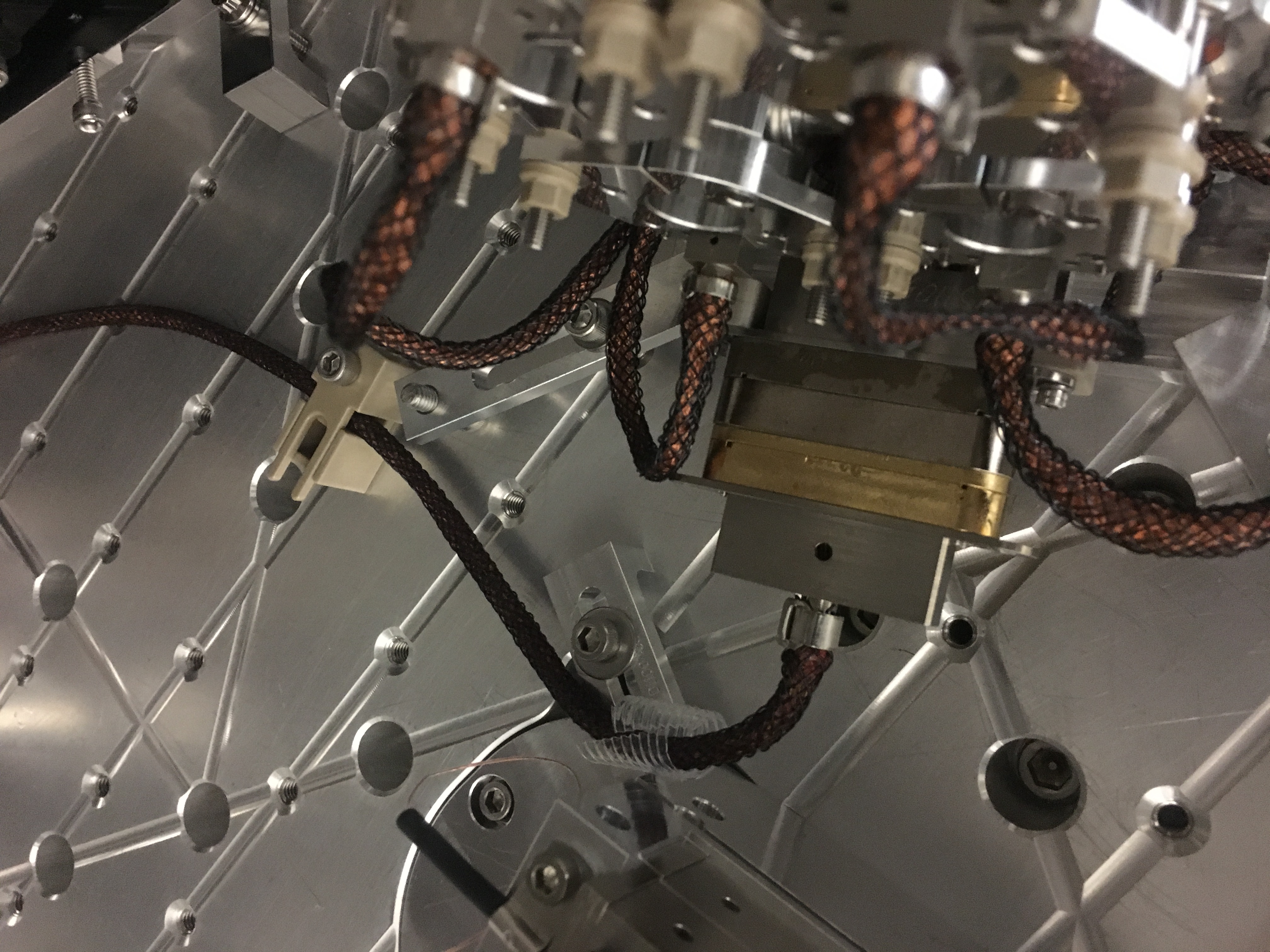
I installed a new cable clamp to pull the cable away from the fast shutter to reduce the pressure (the FS-OM3 distance is so short I was worried about making a kink at the connector if I try to completely pull the cable away from FS) and put a short PEEK tubing that is a leftover from TMS cable insulation (first attachment).
We also observed that wiggling the micro DB cable sometimes changed open/short, and it wasn't clear if this was due to me accidentally touching/affecting DB25 cable or if there's another short circuit path via cable shield. I installed another PEEK tubing to UR coil micro DB cable where it was bending at the edge of the OM3 cage (second attachment, red arrow points the tubing).
After these OM3 was consistently clear of the ground loop.
As a side note, we removed LR coil because I thought (in error) at some point that LR BOSEM was suspect. We put it back in, and measured open counts (20460 or so) and set the depth such that the input becomes half of the open number. We also adjusted LL depth but didn't touch UR and UL as they looked good.
ISI was unlocked
After removing all tools from the ISI table, ISI was unlocked by Corey.
No need for ground loop test again
We didn't touch any of the cables except OM3, so no need to test ground loop again.

In ICS, I've removed the cable (D1000225/S1106893 & gave it a Defect record), which was suspected for causing part of the ground loop for ZM1, from the HAM6 Top Level Assy load & added the new cable (D1000225/S1100410) to the HAM6 sub-assy-load: D1300122.
Note: In D1300122, a D1700316 cable is called out here instead of D1000225. Are these interchangeable?
[Confirmed w/ Hugh that he installed the regular D1000225s because we had limited supply of the D1700316 & they were used for VOPO. Richard M. told Hugh the standard D1000225s were acceptable for the ZM1 suspension.]