kyle.ryan@LIGO.ORG - posted 19:01, Monday 30 April 2018 - last comment - 11:07, Tuesday 01 May 2018(41757)
Vented Vertex, YBM and XBM volumes
Had forgot to log this earlier
Had forgot to log this earlier
This evening, I vented BSC1's annulus volume with UHP N2 and BSC3's with room air as an experiment. I believe that LLO has determined that venting the viton-sealed annulus volumes with dry nitrogen can measurably reduce the subsequent pump downs.
Additionally, I removed all but 4 door bolts from BSC1 N. and BSC3 W. doors. Preliminarily, these remaining four/door bolts had been loosened 1 full turn ccw so as to not over deflect the door flanges when the other bolts were loosened and removed completely..
Also, the bolts on these two door flanges were WAYYYYYYY TOOOOOO TIIIGGGGHHHHTT!!!! and were a complete pain in the "arse" to remove. I vaguely remember someone commenting that this was in response to overhearing talk of us having a potential door leak following the last time that these had been cycled - NOTE TO ALL CONCERNED: Once the mating flanges are in contact with each other, additional torquing of the bolts only results in unnecessary galling etc..... don't do this! The "long" wrenches should never be used to "tighten" door bolts.
Thanks, Kyle! It is also important to not under torque the doors. We found the recent BSC door at EY with loose bolts. Doors should be checked again after a vacuum is pulled if door crew is unsure of adequate torque.
Replaced BSC7 PT170 gauge (Old gauge BPG402) with a new type of guage model number BCG450. Conflat joint will need to be leak tested.
After a bit of a rough start up period (nothing major or unusual, just ALL of the usual little things), we welded in the first fiber to the new ETMx PUM and TM. More tomorrow.
Today we started ramping down CP4 bake temperature after it soaked at 130C for 30 days (minus variances from top to bottom temps).
MCE came on site today to modify the (single sequence) ramp profile. The "holding time" was faulty because the temperature bands were set too narrow (+/- 0.01C). They are now +/-1C so the program can soak and then automatically begin its ramp down. It soaked at 124C for an hour this afternoon and began ramp down around 5pm local at 1C/hr until it reaches room temperature. I will monitor tonight.
We will need to remove the additional 10 kW heater from the circuit when temps approach ~ 100C (I'm guessing).
Part of WP 7519.

Gerardo has gone out to the LVEA to replace PT170 with a BCG450 Inficon gauge (It is currently a BPG402 Inficon gauge). When he is done I will update and restart the software on h0vaclx to match the change.
Work complete. No issues seen. DAQ restart needed at some point.
Summary:
Details:
Summary: We are venting the Vertex to enter HAM5 and access both ITMs, hardware install in all three chambers. Parasitic vacuum work on the Input Mode Cleaner beam tube to replace IP gate valves, work on the PSL continue with mode matching into the PMC, fiber pulling at EX, contractors on site for Richard and Bubba, and APS continues their work (contractor, access control).
Access to MY: Chandra requests that any activity at MY be cleared with her, due to the ongoing bakeout.
VAC:
SUS:
PSL:
Other:
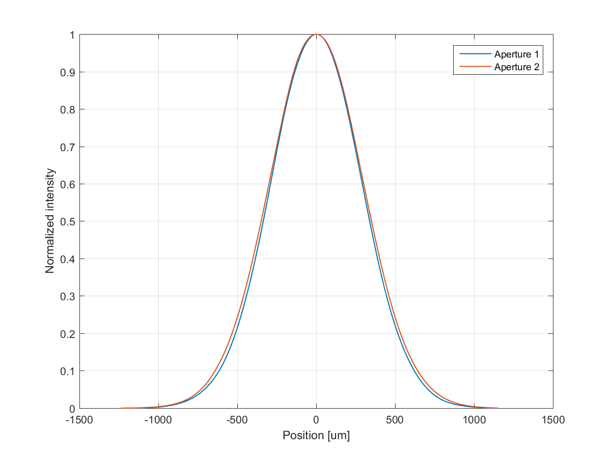
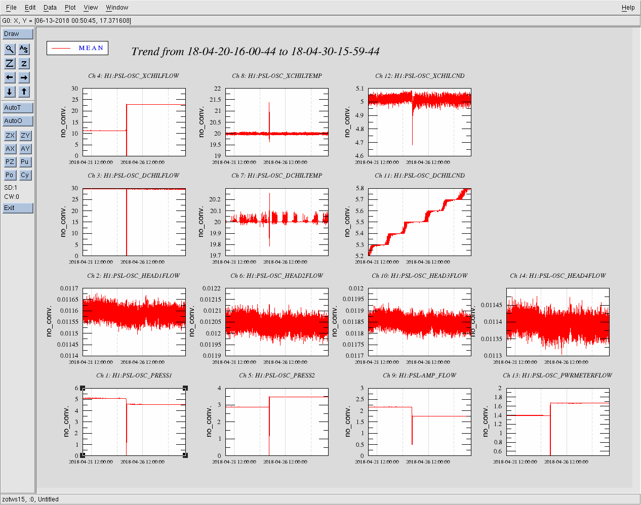
I pulled some data off of the beam profile laptop showing the profiles of our beams in different places. The plots attached are all shifted so that the max intensity is at 0 um and normalized to 1. For some of these beam profiles I don't know which direction is vertical and horizontal.
Below, the beam leaving the OPO platform is a nice guassian with widths that are only 0.2% different between vertical and horizontal apertures.
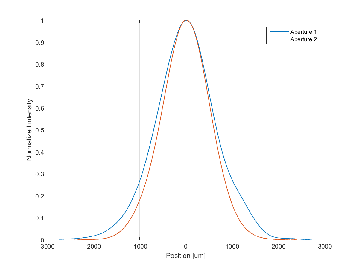
Below is the same plot for the single bounce interferometer beam, I believe this is a reflection off of ITMX (this is data that Terra, T Vo, Sebastian and Dan Brown saved). This is very similar to the plot that Aidan made with Terra's screenshots (41541):
And after the seed beam from the OPO passes through HAM5 it has a variety of shapes, some of which seem clearly clipped, depending on the alignment of ZM2. We didn't do a full exploration of the possible alignments we could achieve with the picomotor, ZM1, and ZM2 because of time constraints, we think though that we have a squeezer beam that is reasonably well aligned to the interferometer beam.
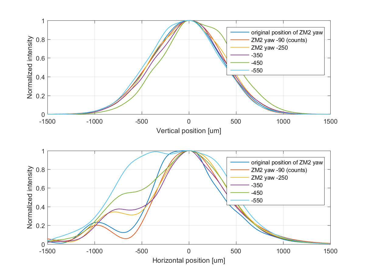
This beam quality issue isn't a show stopper for the level of squeezing that we want to see in O3, as we have seen that it is possible to couple about 90% of the squeezer seed beam into the OMC. This would need to be solved in order to get more squeezing. However, whatever is causing the beam quality issue for the squeezer beam is likely also a source of problems for the interferometer beam, and could potentially be cause more immediate noise problems.
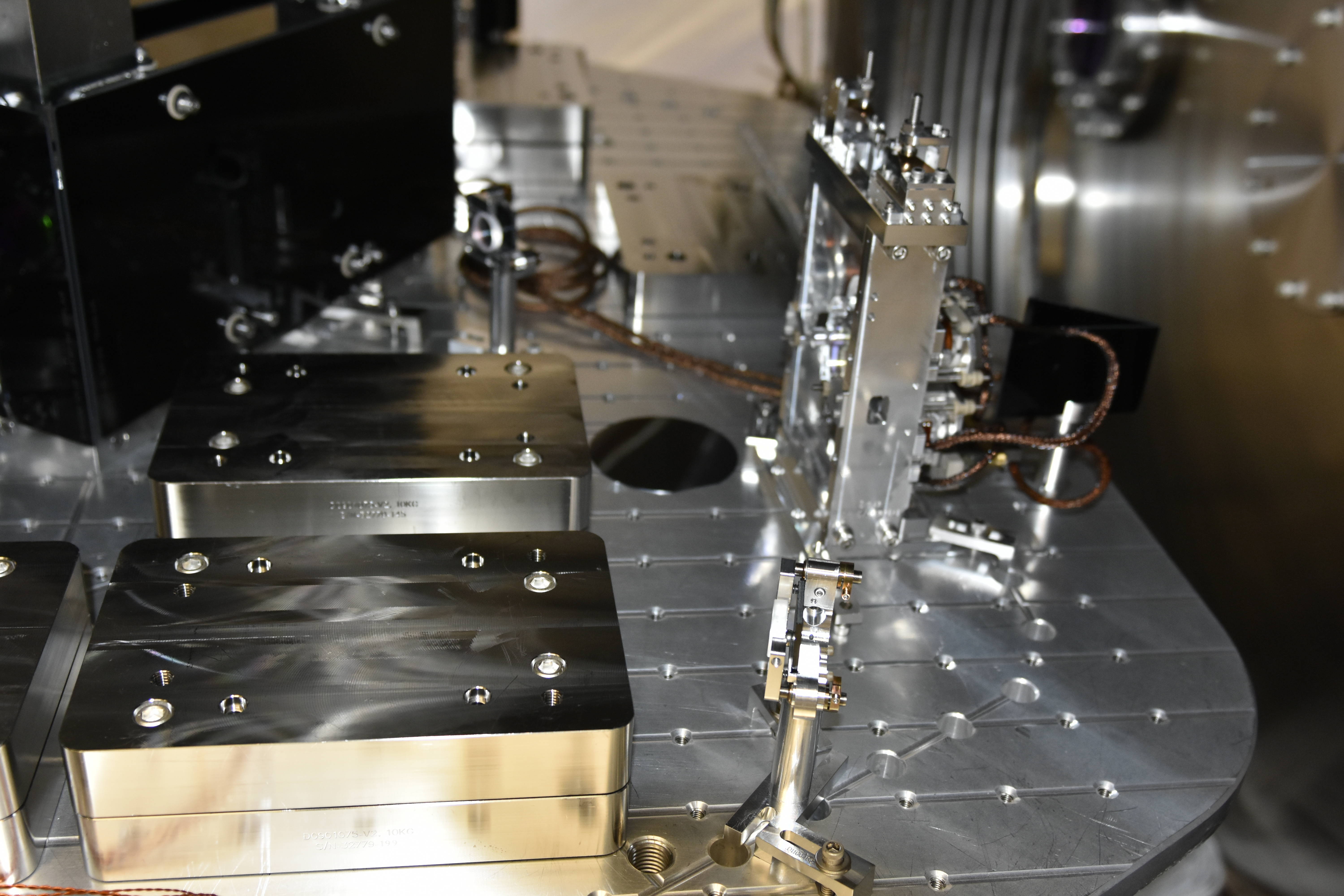
Corey, Jeff B.,

   This morning Corey (1) removed the first contact from the 1" optics attached to the upper part of the OMC weldment, and (2) placed a new 4" witness wafer on the table, located on the +X, +Y side of the table. See attached photo for location.

   Both doors were installed a short time after the wafer was placed.
Was going to open the fluid flow to the LVEA after being in local recirculation mode for a week after changing the filters early last week. But, we (Bartlett & I) found a very slow leak on the fine output filter. It was slow enough that the medium was sticky and dried out rather than flowing. We managed to get a little bit of a turn on the filter and will check on the leak condition later today/tomorrow.
FYI, please don't close the valve that appears to be almost but not completely closed. It is purposely in that state to increase pressure at the filter to expose potential leaks. Not that anyone has done so or even considered doing so, I just wanted to be explicit.
TFs taken this morning before venting, collected because SR2 may be locked and unlocked for the baffle install.
/ligo/svncommon/SusSVN/sus/trunk/HSTS/H1/SR2/SAGM1/Data/
2018-04-30_1534_H1SUSSR2_M1_WhiteNoise_L_0p01to50Hz.xml
2018-04-30_1534_H1SUSSR2_M1_WhiteNoise_T_0p01to50Hz.xml
2018-04-30_1534_H1SUSSR2_M1_WhiteNoise_V_0p01to50Hz.xml
2018-04-30_1534_H1SUSSR2_M1_WhiteNoise_R_0p01to50Hz.xml
2018-04-30_1534_H1SUSSR2_M1_WhiteNoise_P_0p01to50Hz.xml
2018-04-30_1534_H1SUSSR2_M1_WhiteNoise_Y_0p01to50Hz.xml
- Cheryl, JeffK
Chandra, Dave:
Chandra requested that the CP4 thermocouple alarm channels be removed from the system:
This was done and the system was restarted.
Also, while contractor work is ongoing at EY, I have bypassed the beam tube CC alarm until 5pm PDT today:
J. Kissel

Since HAM5 has been up-and-down to air several times since ZM2 and the actuators for the OFI have been installed, it's taken us a while to get their first in-vacuum, clean set of transfer functions. Today is the day! ...Just before we vent again this morning.

Raw data lives here:
/ligo/svncommon/SusSVN/sus/trunk/HTTS/H1/ZM2/SAGM1/Data/
2018-04-30_1545_H1SUSZM2_M1_WhiteNoise_L_0p02to50Hz.xml
2018-04-30_1545_H1SUSZM2_M1_WhiteNoise_P_0p02to50Hz.xml
2018-04-30_1545_H1SUSZM2_M1_WhiteNoise_Y_0p02to50Hz.xml

/ligo/svncommon/SusSVN/sus/trunk/OFIS/H1/OFI/SAGM1/Data
2018-04-30_1547_H1SUSOFI_M1_WhiteNoise_L_0p02to50Hz.xml
2018-04-30_1547_H1SUSOFI_M1_WhiteNoise_T_0p02to50Hz.xml
2018-04-30_1547_H1SUSOFI_M1_WhiteNoise_Y_0p02to50Hz.xml


Will process in detail later, but as expected the results look great.
EY tripped off at 16:33UTC (9:33PT). Snapshot attached show state when tripped.
J. Kissel

In prep for doors this morning, I've re-checked the health of the suspensions which had ground loop fix surgery this past Friday evening (LHO aLOG 41722).

Both transfer functions testing the full sensor-actuator chain and high-frequency ASD of the OSEM sensors look good. Will process in detail later.


/ligo/svncommon/SusSVN/sus/trunk/HTTS/H1/ZM1/SAGM1/Data/
2018-04-30_1528_H1SUSZM1_M1_WhiteNoise_L_0p02to50Hz.xml
2018-04-30_1528_H1SUSZM1_M1_WhiteNoise_P_0p02to50Hz.xml
2018-04-30_1528_H1SUSZM1_M1_WhiteNoise_Y_0p02to50Hz.xml
2018-04-30_1544_H1SUSZM1_OSEM_Noise_ASDs.xml

/ligo/svncommon/SusSVN/sus/trunk/HTTS/H1/OM3/SAGM1/Data/
2018-04-30_1526_H1SUSOM3_M1_WhiteNoise_L_0p02to50Hz.xml
2018-04-30_1526_H1SUSOM3_M1_WhiteNoise_P_0p02to50Hz.xml
2018-04-30_1526_H1SUSOM3_M1_WhiteNoise_Y_0p02to50Hz.xml
2018-04-30_1544_H1SUSOM3_OSEM_Noise_ASDs.xml
Related entries:
https://alog.ligo-wa.caltech.edu/aLOG/index.php?callRep=29416
https://services.ligo-la.caltech.edu/FRS/show_bug.cgi?id=6446
Summary:
For a very long time we've been limping along with some of the TMSX BOSEMs (namely F1, LF and RT) somehow seemingly less sensitive than they used to be (see the above alog and FRS).
By merely pushing BOSEMs closer to the magnets using adjustment nuts and roughly setting them to half the open value, the response of these BOSEMs were restored.
We also changed RT BOSEM (SN 164) to the one Betsy gave us (SN 083) because we could, but it was unnecessary in a retrospect. We won't change it back because it's a pain.
Details:
We measured the OSEMINF_INMON for suspected ones fully open by pulling BOSEMs away from the mass using adjustment nuts. (In the case of RT we removed the BOSEM plate from the cage and didn't see a large change.)
We found that all of them were already very close to the open values, and that open values were smaller than they used to be judging from the offsets that were set a long time ago. The former means that BOSEM bodies are much farther away from the magnets than they used to be. Apparently TMSX sagged and rolled.
|
OSEMINF_INMON before (counts) |
Open count | 2*|Offset| before | |
| F1 | 19.1k | 21.1k | 25.44k |
| LF | 18.1k | 18.7k | 23.16k |
| RT | 21.4k | 22.1k (26.95k after the swap) | 26.172k |
We swapped RT (SN 164) with the known good one (SN 083). No particular reason for the choice of RT rather than LF, it's just that Corey was working on RT at that time and thus was convenient to test.
We set the offsets to half the corresponding open count, and adjusted the BOSEM depth so that they come close to the offset.
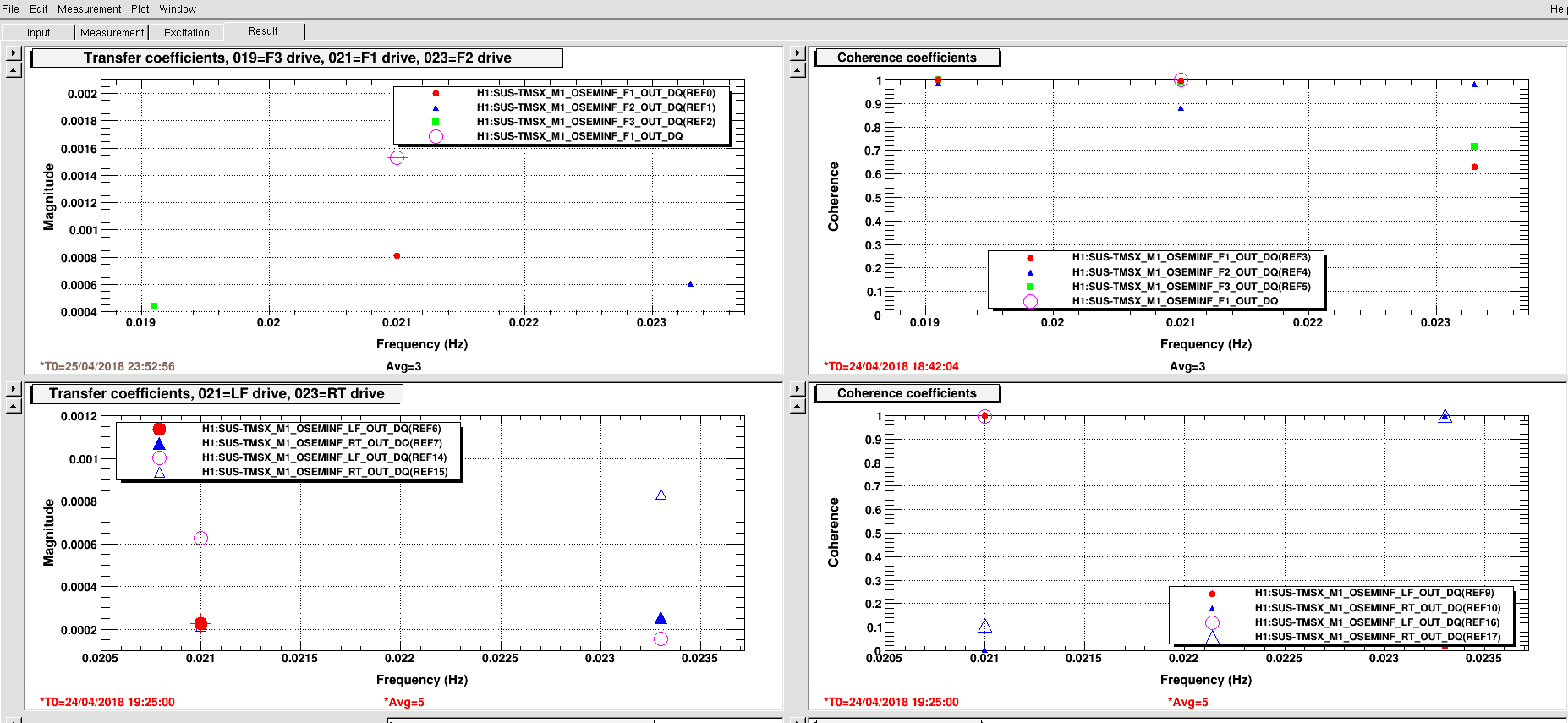
The attachment shows the coil to coil transfer coefficient (OSEMINF/COILOUTF_EXC) at about 0.02 Hz before/after the change for F1, LF and RT (it also shows F2 and F3 but there's no "after" for these). You want to compare pink open circle with red solid disk, or blue open triangle with blue solid triangle.
As you can see the sensitivity increased by a factor of 1.9 for F1, 2.75 for LF and 3.3 for RT.
| Measurement before | Measurement after | sensitivity increase (after/before) | |
| F1 | 8.1e-4 | 1.53e-3 | 1.9 |
| LF | 2.28e-4 | 6.27e-4 | 2.8 |
| RT | 2.54e-4 | 8.34e-4 | 3.3 (=1.2*2.8) |
As for RT, a factor of 1.2 came from the increase in the LED power (26.95k/22.1k=1.22), so the change caused by the depth of OSEM is 3.3/1.2=2.8, almost the same as LF.
I removed a factor of 3 that was added to the PIT damping gain at some point, now all damping gains are 1 (except SD).
I'm also somewhat worried about TMSY LF and RT just because the OSEMINF_INMON is much larger than the offset (second attachment). However, similar measurement for TMSY (third attachment, left half is TMSX, right half is TMSY), it doesn't look as if F3 and LF are terrible.
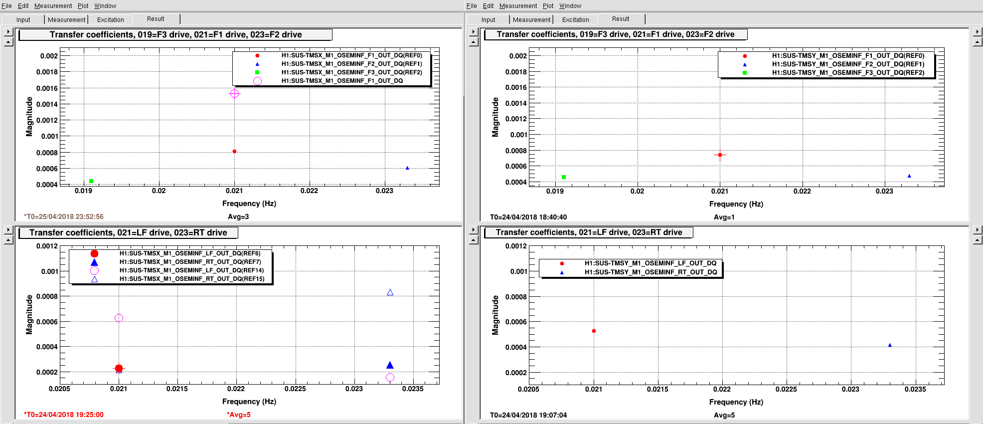
It seems as if TMS sank and LED lost power at the same time, so it would have been difficult to judge what was going on just by looking at the data.
J. Kissel
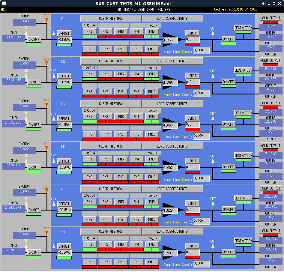
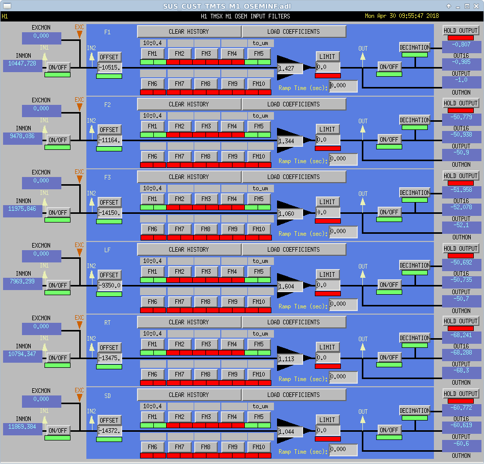
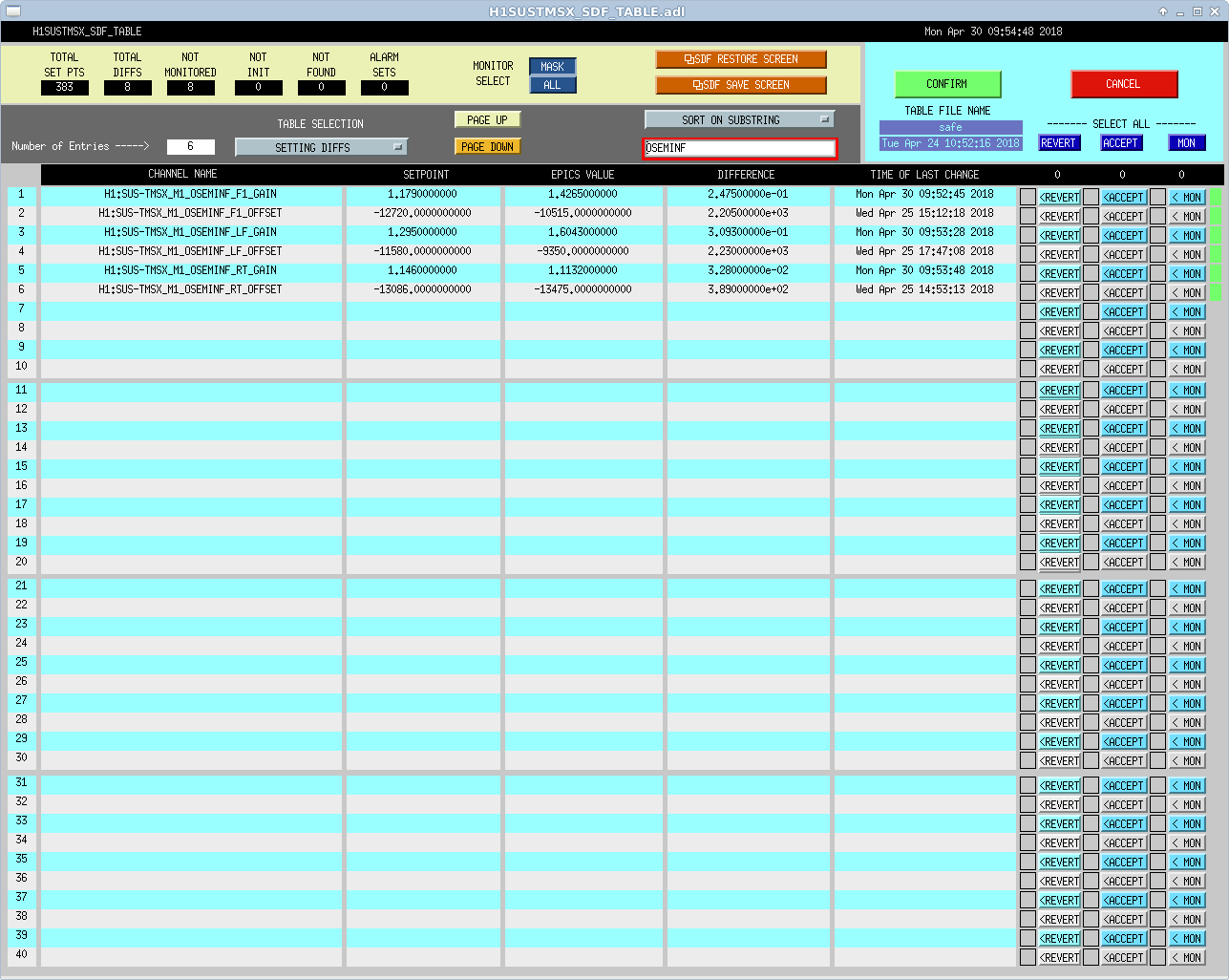
I've completed the update to the open light current compensation in the OSEMINF filters by installing the normalization gains (H1:SUS-TMSX_M1_OSEMINF_${DOF}_GAIN) for the above updated OSEMs (F1, LF and RT), and then accepted the new offsets and gains in the SDF system. See attached screenshots, but for the sake of future searchability:
OSEM Open Light Current OFFSET GAIN
(ADC counts) (OLC / -2) (30000/OLC)
F1 21030 -10515 1.4265
LF 18700 -9350 1.6043
RT 26950 -13475 1.1132

Measured dew point just before venting was -28C.