yannick.lecoeuche@LIGO.ORG - posted 13:04, Wednesday 25 April 2018 (41666)
Weekly PSL Chiller Reservoir Top-Off
FAMIS 6572
Added 25 mL to crystal chiller.
FAMIS 6572
Added 25 mL to crystal chiller.
Attached are the VPW desiccant plots with the last month's added data. Nothing out of the ordinary shown.
Got pretty close to ideal position: Residual from there: -5um, -3, 10, 1urad, 0, & -2 for dX, dY, dZ, dRX, dRY, & dRZ. So pretty close.
The SEI Manager is in ISI_DAMPED_HEPI_OFFLINE. If the ISI needs to be ISOLATED, that will have to be done via the ISI Guardian, just don't try that with the SEI Guardian.
We had an unexplained timing glitch on h1seih45 around 10am PDT which stopped all models from running on this system. Each model reported an ADC timeout error. I stopped and restarted all the models without any issues.
(Gray, Radkins)
In preparation for sealing up HAM6, SQZT6 Table location marked (hung plumb bob off 3 corners and marked on floor. The table is currently on its wheels (vs on the fixed feet which are landed on the silver feet bases when tables are finally located.). Marks made today are for the X-location of the table. When table can be moved into its final location, we'll use the marks and roll the table in the +Y direction closer to HAM6.
Next Items for this table (& ISCT6...which already had it's location marked):
Secure all optical / electrical components
Disconnect electronics cable connections, stow cables safely
(Carefully) Disconnect optical fiber connections, stow fibers safely
Then we'll move both tables out of the way for HAM6 door installation.
By Jameson Rollins and Jonathan Hanks
Soon after the new guardian machine (h1guardian1 [0]) was moved into production (i.e. after all guardian nodes were moved to the new machine) we started seeing efence and valgrind but never saw a crash in either case, presumably either because the MTTF was increased significantly or because the crashes were circumvented entirely by serialized system calls (valgrind).
Adding to the confusion was the inability to reproduce the crashes in a test environment. 50 test guardian nodes running under the new production environment, subscribing to hundreds of front end channels (but with no writes), and with test clients subscribed to all control channels, failed to show any crashes in two weeks of straight running. (See below for the later discovered reason why this was.)
The following steps were taken to help diagnose the problem:
Inspection of the coredumps generally turned up no useful information other than the problem was a memory corruption error, likely in the EPICS CAS (or in the pcaspy python wrapping of it). The relatively long MTTF pointed to a threading race condition.
[0] Configuration of the new h1guardian1 machine:
[1] systemd-coredump is a very useful package. All core dump files are logged and archived and the coredumpctl command provides access to those logs and an easy means for viewing them with gdb. Unfortunately the log files are cleared out by default after 3 days, and there's there doesn't seem to be a way to increase the expiration time. So be sure to backup the coredump files from /var/lib/systemd/coredump/ for later inspection.
In an attemp to get more informative error reporting with less impact on performance, Jonathan compiled python2.7 and pcaspy with libasan, the address sanitizer. libasan is similar to valgrind in that it wraps all memory allocation calls to detect memory errors that commonly lead to seg faults. But it's much faster and doesn't serialize the code, thereby leaving in place the threads that were likely triggering the crashes.
(As an aside, libtsan, the thread sanitizer, is basically impossible to use with python, since the python core itself seems to not be particularly thread safe. Running guardian with python libtsan caused guardian to crash immediately after launch with ~20k lines of tsan log output (yes, really). So this was abandoned as an avenue of investigation.)
Once we finally got guardian running under libasan [0], we started to observe libasan-triggered aborts. The libasan abort logs were consistent:
==20277==ERROR: AddressSanitizer: heap-use-after-free on address 0x602001074d90 at pc 0x7fa95a7ec0f1 bp 0x7fff99bc1660 sp 0x7fff99bc0e10
WRITE of size 8 at 0x602001074d90 thread T0
    #0 0x7fa95a7ec0f0 in __interceptor_strncpy (/usr/lib/x86_64-linux-gnu/libasan.so.3+0x6f0f0)
    #1 0x7fa94f6acd78 in aitString::copy(char const*, unsigned int, unsigned int) (/usr/lib/x86_64-linux-gnu/libgdd.so.3.15.3+0x2bd78)
    #2 0x7fa94f6a8fd3  (/usr/lib/x86_64-linux-gnu/libgdd.so.3.15.3+0x27fd3)
    #3 0x7fa94f69a1e0 in gdd::putConvert(aitString const&) (/usr/lib/x86_64-linux-gnu/libgdd.so.3.15.3+0x191e0)
    #4 0x7fa95001bcc3 in gdd_putConvertString pcaspy/casdef_wrap.cpp:4136
    #5 0x7fa95003320d in _wrap_gdd_putConvertString pcaspy/casdef_wrap.cpp:7977
    #6 0x564b9ecccda4 in call_function ../Python/ceval.c:4352
...
    #67 0x564b9eb3fce9 in _start (/opt/python/python-2.7.13-asan/bin/python2.7+0xd9ce9)
0x602001074d90 is located 0 bytes inside of 8-byte region [0x602001074d90,0x602001074d98)
freed by thread T3 here:
    #0 0x7fa95a840370 in operator delete[](void*) (/usr/lib/x86_64-linux-gnu/libasan.so.3+0xc3370)
    #1 0x7fa94f6996de in gdd::setPrimType(aitEnum) (/usr/lib/x86_64-linux-gnu/libgdd.so.3.15.3+0x186de)
previously allocated by thread T0 here:
    #0 0x7fa95a83fd70 in operator new[](unsigned long) (/usr/lib/x86_64-linux-gnu/libasan.so.3+0xc2d70)
    #1 0x7fa94f6acd2c in aitString::copy(char const*, unsigned int, unsigned int) (/usr/lib/x86_64-linux-gnu/libgdd.so.3.15.3+0x2bd2c)
Thread T3 created by T0 here:
    #0 0x7fa95a7adf59 in __interceptor_pthread_create (/usr/lib/x86_64-linux-gnu/libasan.so.3+0x30f59)
    #1 0x564b9ed5e942 in PyThread_start_new_thread ../Python/thread_pthread.h:194
SUMMARY: AddressSanitizer: heap-use-after-free (/usr/lib/x86_64-linux-gnu/libasan.so.3+0x6f0f0) in __interceptor_strncpy
Shadow bytes around the buggy address:
  0x0c0480206960: fa fa fd fa fa fa 00 fa fa fa fd fd fa fa fa fa
  0x0c0480206970: fa fa fd fd fa fa fd fd fa fa fd fd fa fa fd fd
  0x0c0480206980: fa fa fd fd fa fa fd fa fa fa fa fa fa fa fd fd
  0x0c0480206990: fa fa fa fa fa fa fd fa fa fa fd fa fa fa fd fa
  0x0c04802069a0: fa fa fa fa fa fa 00 fa fa fa fa fa fa fa fd fa
=>0x0c04802069b0: fa fa[fd]fa fa fa fd fd fa fa fd fd fa fa 00 fa
  0x0c04802069c0: fa fa fd fd fa fa fd fd fa fa fd fd fa fa fd fd
  0x0c04802069d0: fa fa 00 fa fa fa fd fa fa fa fd fd fa fa fd fa
  0x0c04802069e0: fa fa fa fa fa fa fd fa fa fa 00 fa fa fa fd fd
  0x0c04802069f0: fa fa 00 fa fa fa fd fd fa fa fd fd fa fa fd fd
  0x0c0480206a00: fa fa fd fd fa fa fd fd fa fa fd fd fa fa 00 fa
Shadow byte legend (one shadow byte represents 8 application bytes):
  Addressable:           00
  Partially addressable: 01 02 03 04 05 06 07
  Heap left redzone:       fa
  Heap right redzone:      fb
  Freed heap region:       fd
  Stack left redzone:      f1
  Stack mid redzone:       f2
  Stack right redzone:     f3
  Stack partial redzone:   f4
  Stack after return:      f5
  Stack use after scope:   f8
  Global redzone:          f9
  Global init order:       f6
  Poisoned by user:        f7
  Container overflow:      fc
  Array cookie:            ac
  Intra object redzone:    bb
  ASan internal:           fe
  Left alloca redzone:     ca
  Right alloca redzone:    cb
==20277==ABORTING
Here's a stack trace from a similar crash (couldn't find the trace from the exact same process, but the libasan aborts are all identical):
    Stack trace of thread 18347:
    #0  0x00007fe5c173efff __GI_raise (libc.so.6)
    #1  0x00007fe5c174042a __GI_abort (libc.so.6)
    #2  0x00007fe5c24ae329 n/a (libasan.so.3)
    #3  0x00007fe5c24a39ab n/a (libasan.so.3)
    #4  0x00007fe5c249db57 n/a (libasan.so.3)
    #5  0x00007fe5c2442113 __interceptor_strncpy (libasan.so.3)
    #6  0x00007fe5b7bf2d79 strncpy (libgdd.so.3.15.3)
    #7  0x00007fe5b7beefd4 _ZN9aitString4copyEPKcj (libgdd.so.3.15.3)
    #8  0x00007fe5b7be01e1 _Z10aitConvert7aitEnumPvS_PKvjPK18gddEnumStringTable (libgdd.so.3.15.3)
    #9  0x00007fe5b8561cc4 gdd_putConvertString (_cas.so)
    #10 0x00007fe5b857920e _wrap_gdd_putConvertString (_cas.so)
    #11 0x000055f7f0c86da5 call_function (python2.7)
"strncpy" is the known-problematic string copy function, in this case used to copy strings into the EPICS GDD type used by the channel access server.
GDB backtraces of the core files show that string being copied was always "seconds". The only place that the string "seconds" is used in guardian is as the value of the "units" sub-record given to pcaspy for the EXECTIME and EXECTIME_LAST channels.
[0] systemd drop-in file used to run guardian under libasan python/pcaspy (~guardian/.confg/systemd/user/guardian@.service.d/instrumented.conf):
[Service]
Type=simple
WatchdogSec=0
Environment=PYTHONPATH=/opt/python/pcaspy-0.7.1-asan/build/lib.linux-x86_64-2.7:/home/guardian/guardian/lib:/usr/lib/python2.7/dist-packages
Environment=ASAN_OPTIONS=abort_on_error=1:disable_coredump=0
ExecStartPre=
ExecStart=
ExecStart=/opt/python/python-2.7.13-asan/bin/python -u -t -m guardian %i
The discovery that the crash was caused by copying the string "seconds" in CAS led to the revelation about why the test setup had not been reproducing the crashes. The "units" sub-record is part of the EPICS DBR_CTRL_* records and is the only sub-record being used of string type. The test clients were only subscribing to the base records of all the guardian channels, not the DBR_CTRL records. MEDM, on the other hand, subscribes to the CTRL records. Guardian overview screens are open all over the control room, subscribing to all the CTRL records of all the production guardian nodes.
CTRL record subscriptions involve copying the "units" string sub-record, and therefore trigger the crashes. No CTRL record subscriptions, no crashes.
So this all led us to take a closer look at how exactly guardian was using pcaspy.
The pcaspy documentation implies that pcaspy is thread safe. The package even provides a helper function that runs the server in a separate thread for you. The implication here is that running the server in a separate thread and pushing/pulling channel updates from/to a main thread into/out of the cas thread is safe to do. Guardian was originally written to run the pcaspy.Server in a separate thread explicitly because of this implication in the documentation.
The main surface for threading issues in the guardian usage of pcaspy was between client writes that trigger pcaspy.Driver.setParams() and pcaspy.Driver.updatePVs() calls inside of pcaspy.Driver.write(), and status channel updates being pushed from the main daemon thread in to the driver that also trigger updatePVs. At Jonathan's suggestion all guardian interaction with the core pcaspy cas functions (Driver.setParams(), Driver.updatePVs()) were wrapped with locks. But we were skeptical that this would actually solve the problem, though, since pcaspy itself provides no means to lock it's internal reading of the updated PVs for shipment out over the EPICS CTRL records (initiated during pcaspy.Server.process()). And in fact this turned out to be correct; crashes persisted even after the locks were in place.
We then started looking into ways to get rid of the separate pcaspy thread altogether. The main daemon loop runs at 16 Hz. The main logic in the daemon loop takes only about 5 ms to run. This leaves ~57 ms to run Server.process(), which should be plenty of time to process the cas without slowing things down noticeably. Moving the CAS select processing into the dead time of the main loop forces the main loop to keep track of it's own timing. This has the added benefit of allowing us to drop the separate clock thread that had been keeping track of timing, elliminating two separate threads instead of just one.
So a patch was prepared to eliminate the separate CAS thread from guardian, and it was tested on about a half dozen nodes. No crashes were observed after a day of running (far exceeding the previous MTTF).
A new version of guardian was wrapped up and put into production, and we have seen no spontaneous segfaults in nearly a week. We will continue to monitor the system to confirm that the behavior has not been adversely affected in any way by the ellimination of the CAS thread (full lock recovery would be the best test of that), but we're fairly confident the issue has been resolved.
pcaspy and CAS are not thread safe. This is the main take away. It's possible that guardian is the most intensive user of this library out there, which is why this has not been seen previously. I will report the issue to the EPICS community. We should be more aware of how we use this library in the future, and avoid running the server in a separate thread.
Multi-threading is tricky.
A quick followup about systemd-coredump. It's possible to control the expiration of the coredump files by dropping the following file into the file system:
root@h1guardian1:~# cat /etc/tmpfiles.d/00_coredump.conf
d /var/lib/systemd/coredump 0755 root root -
root@h1guardian1:~#
The final "-" tells systemd-tmpfiles to put no expiration on files in this directory. The "00" prefix is needed to make sure it always sorts lexically before any config that would set the expiration on this path (the system default is in /usr/lib/tmpfiles.d/systemd.conf).
The GN2 temp was running low at around 120C. I raised the variac from 60% to 64%. As we run the Dewar dry, we will try to maintain a temperature around 180C. Dewar is currently 43% full, with a ~7%/day consumption. Flow is 40-50 scfhx100.
I valved out the UHP GN2 from the turbo foreline; foreline pressure is back to 7.1e-3 Torr.
GN2 temps rising over 200C this afternoon, so I a) lowered the variac from 64% to 60% and b) opened the pressure build valve by another 1/8 turn + 1/4 turn (I believe it's open 1/2 turn total now). The Dewar head pressure has fallen today from 17 to 16 psig. The late afternoon sun adds a variable. Flow was low ~20 scfhx100.
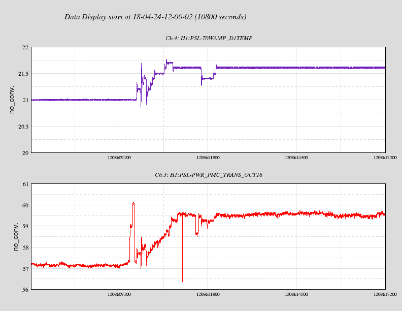
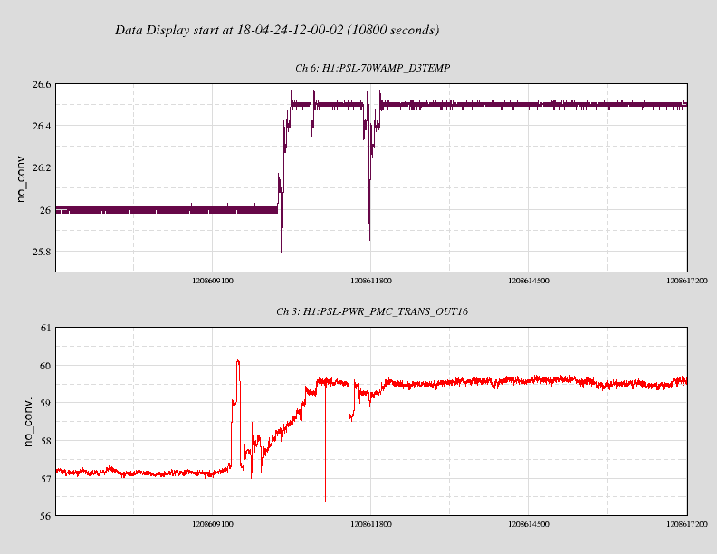
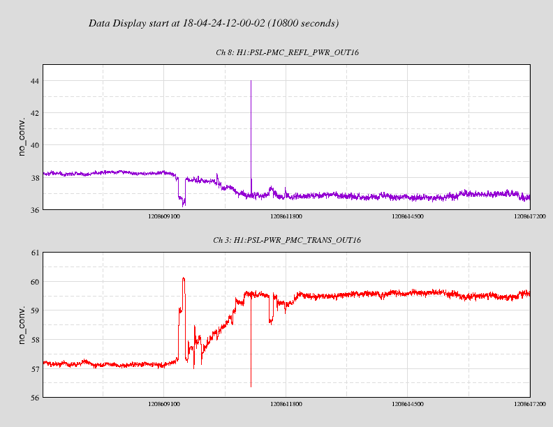
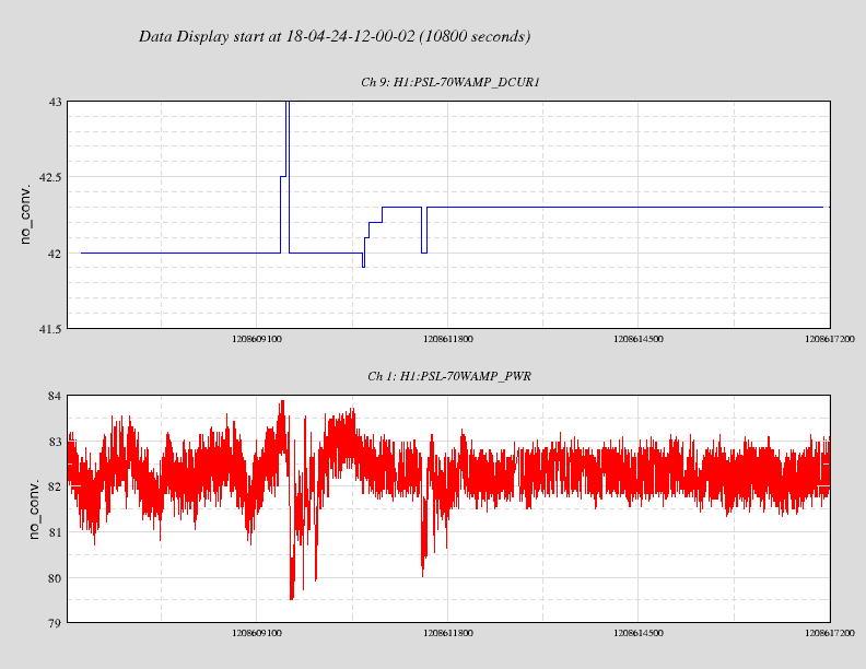
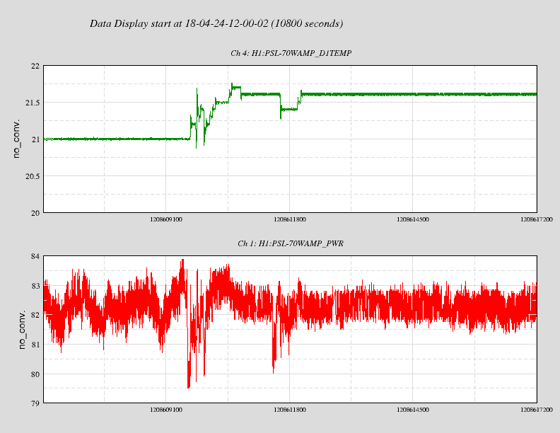
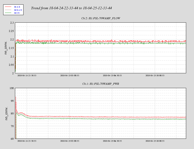
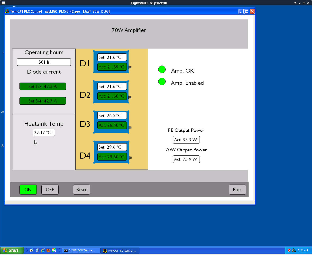
The operating current and diode temperatures of the 70 W amplifier were adjusted to improve the
output of the pre-modecleaner.

    The first two plots show the increase in diode temperatures and the corresponding increase
in pre-modecleaner transmitted power.  The third plot shows the pre-modecleaner transmitted power
and reflected power over the same time period.  The fourth and fifth plots show the output of the
70 W amplifier as the diode temperatures and diode currents were manipulated.

    Whilst the diode temperatures and currents were varied, the output of the 70 W amplifier did
not vary appreciably.  The pre-modecleaner output increased by ~2 W and the reflected power decreased
by ~1 W.

   With the diode current and temperature tunings, the output mode of the 70 W amplifier is
better matched to the pre-modecleaner and didn't not significantly affect the output power of the amplifier.
Sheila, Dan Brown, Alexei, TVo
Because we were a bit distrusting of last night's OMC mode scan measurements, we looked at the beam quality going into HAM5 from the squeezer and it showed a pretty nice symmetric Gaussian beam.
However, when we looked at the beam quality coming into HAM6, we saw that the vertical direction was 1500um and horizontal was 2100um at about 1.36 meters upstream from OM1. Which means something in HAM5 is causing this odd astigmatism. Dan roughly calculated that the differential pressure between the air side and the vacuum side wil result in a ~hundreds of meter lensing effect and if we're going to the lens an offset+misaligned angle then it's possible we could see some astigmatism, but not to the level that we're seeing here. A thought could be the Faraday, but it's not clear how to definitively determine that.
We were able to see clipping with the Nanoscan on the IFO side and tried to get rid of this effect by moving around ZM1 and ZM2. We were able to bring the astigmatism down from [1500um, 2100um] to [1500um,1800um], which is still a lot but we decided to give this configuration another OMC mode scan with various lens positions, which Dan will post as a comment. After the fact, we measured some more beam profiles to try to fit more q-parameters on the IFO side as well as OPO in the further field on SQZT6 with the beam diverter.
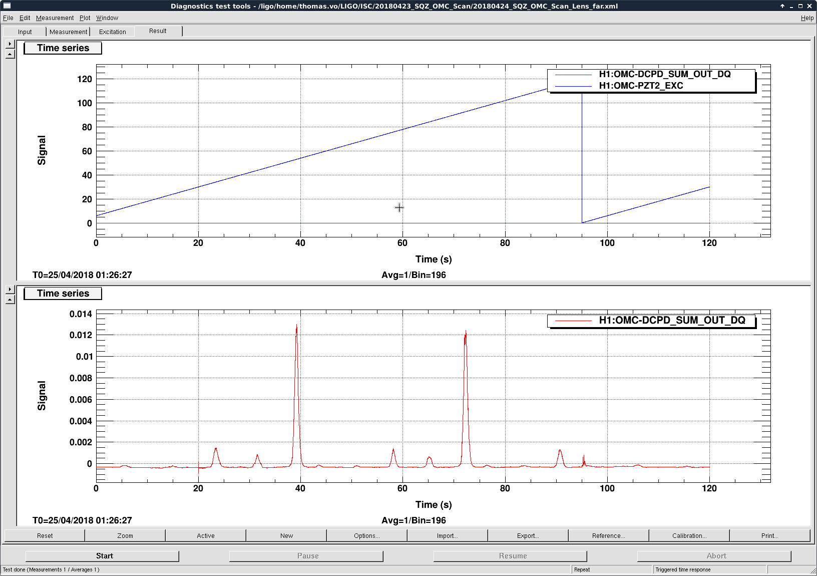
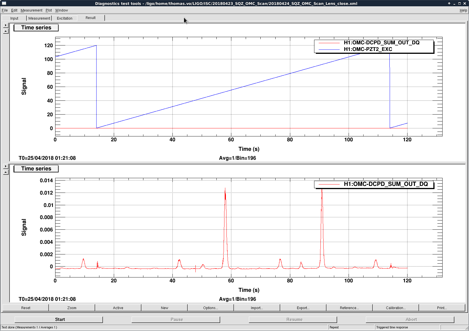
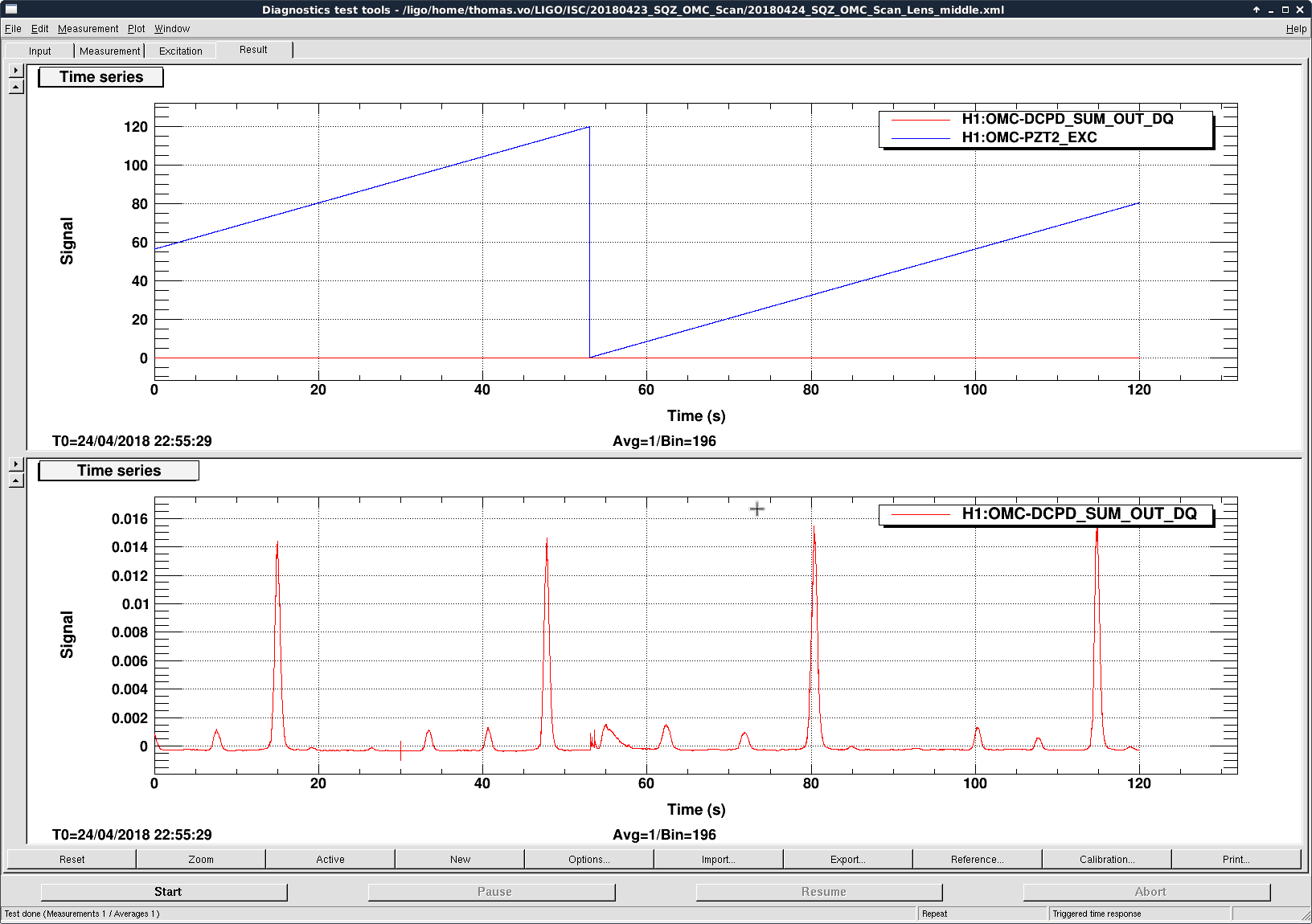
Attached are the OMC scans using the OPO beam after reducing the astigmatism mentioned above, these are looking much cleaner compared to last night. Far, close, and middle refer to the lens translation stage position relative to the OPO. Taking the ratio of the 2nd order and 0th order peaks we can estimate the mismatch as: close = 89%, middle = 90%, and far = 87%, which isn't as high as we'd hoped. Analysis of the beam profiling of the new lens setup to come.
Powered up and seems to work. Tested with a flashlight. Got DC readback at both DVM and beckhoff.
Chandra requested that the cell phone alarms for PT245B be sent immediately, rather than having a 5 minute "warm up" time. System was restarted with the new configuration.
TITLE: 04/24 Day Shift: 15:00-23:00 UTC (08:00-16:00 PST), all times posted in UTC
STATE of H1: Planned Engineering
INCOMING OPERATOR: None
SHIFT SUMMARY:
Bootfest Happened. Also Squeezer work continues. All other activities below.
LOG:
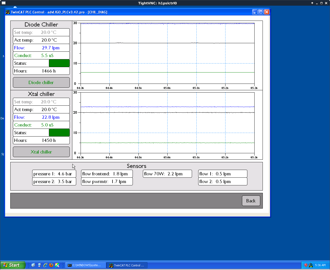
Peter K., Jeff B.

   We made several adjustments to the PSL cooling system:

   (1). Changed the Crystal chiller filters inside and outside the enclosure.
   (2). Closed off the chiller bypass to increase the flow from ~11 l/m to 22.5 l/m.
   (3). Opened the throttling valve inside the enclosure to reduce turbulence noise in the manifold.
   (4). Adjusted the Frontend, Power Meter, and 70W Amp flows back to within specs.

   These adjustments should help reduce the noise from the cooling system in the PSL.
With the reduced cooling water flows, the output of the 70 W amplifier was reduced by ~4 W.
The pre-modecleaner output over the same time improved a little, or more correctly returned
to its previous.  The uptick at the end of the plot is due to my adjusting the alignment into
the pre-modecleaner with the Picomotors.
This morning Kyle valved back in the pressure build circuit on CP4 Dewar by opening the valve 1/4 turn CCW. The head pressure is now 17 psig and flow is between 50-60 scfhx100. The GN2 temperature dropped as a result to below 150C, so I increased the variac from 56% to 58%.
Increased variac to 60%. GN2 temps 150-160C. Leaving as-is overnight.
With this set of measurement we should be able to grab power measurement from either ISCT6 or SQZT6 and figure out what goes into the OPO and what comes out of the OPO.
At the time 11mW was measured at ISCT6 input coupler. The SHG launch DC diode resistivity has been adjusted to agree with the measurement. From 0.192 A/W to 0.22 A/W. The change has been accepted in the SDF. BS reflectivity is 6.2%. So 6.2% of what SHG_LAUNCH_DC reads should equal to what goes in to the fiber coupler.
Green power measured at VOPO fiber was 3.3 mW (30% drop from ISCT6). 14% loss by the time the beam come out to the SQZT6 and hit the refl PD. Sheila believes this is due to the thin film polarizer.
The OPO refl diode calibration was fine tuned just today (resistivity was 0.22 A/W, now 0.21 A/W). It should reads 14% of what comes out of the OPO.
The measurement was taken while scanning the cavity at 1Hz.
After reading the BBPD design document more carefully I realized the DC transimpedance and responsivity is quite difference for green. The calibration has been changed to 0.3 A/W responsivity and 1400 Ohms transimpedance for the OPO green refl PD. V/W calibration here is still the same. SDF difference accepted.
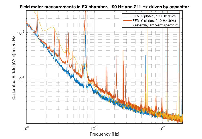
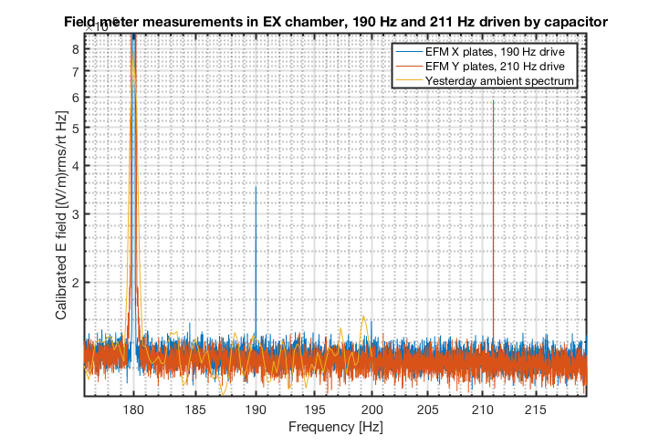
Calibration of the field meter does not need knowledge of the input capacitance. With the calibration plates, the electic field
on the sense plate is simply  E(cal)= V(cal)/d where d is the calibration-sense plate separation. If you want to improve the accuracy you will need to account for the thickness of the copper disk on the sense plate and a few percent error due to the fringing field.

The current sensitivity curves are pretty close to the ones measured in the prototype. How did you handle the factor of 2 due to the two plates on each coordinate and the output which is the difference?
We were a little confused about how to calibrate the EFM. It's not such an easy problem as it first seems.Calibration Plate Voltage to Electric Field TF
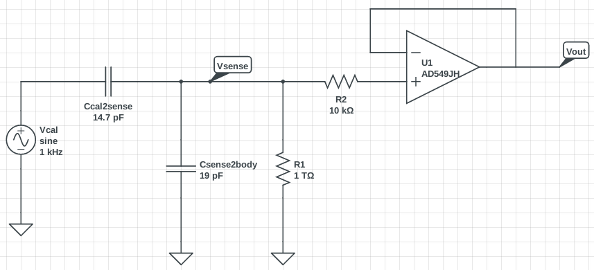
V_cal refers to the potential difference between the calibration plate and ground. Ground is connected to the body of the EFM. The sensor plate is kept isolated and should be at voltage V_sense = V_cal * d2/(d1 + d2) where d1 is the distance between the cal plate and sensor plate, and d2 is the distance between the sensor plate and the body. If we assume that the electric field E_cal is constant over the entire EFM, then I think we ought to be using the total distance d = d1 + d2 between the calibration plate and body for E_cal = V_cal/d. d1 = 1/2 inch = 1.27 cm, and d2 = 5/8 inch = 1.59 cm, so d ~ 2.86 cm and E_cal/V_cal = 1/d ~ 35.0 (V/m)/V using this method. However, we became concerned about the geometry of the EFM affecting this result. There is a copper disk which connects the sensor plate to the sensor pin, and there are a bunch of large screws between the sensor plate and the body. We decided to compute an "effective distance" using the capacitances we measured between the cal and sense plates (~11pF), and the sense plate and the body (~19pF) via E = Q/(2 A e0), where A is the area of the plates (~0.01 m^2), e0 is the vacuum permittivity, and Q is the charge on the cal plate. Q = C V, so we can recover E/V = C/(2 A e0) = 1/d, so our effective distance d = (2 A e0)/C, where C is the total capacitance between the cal plate and the body (~7pF). Using this method, E/V ~ 38.9 (V/m)/V, not much different than our result from 1/d. This is the number we used to calibrate from V_cal to E_cal. I don't know what value was used for the initial prototype.Differential Amplifier Factor of Two
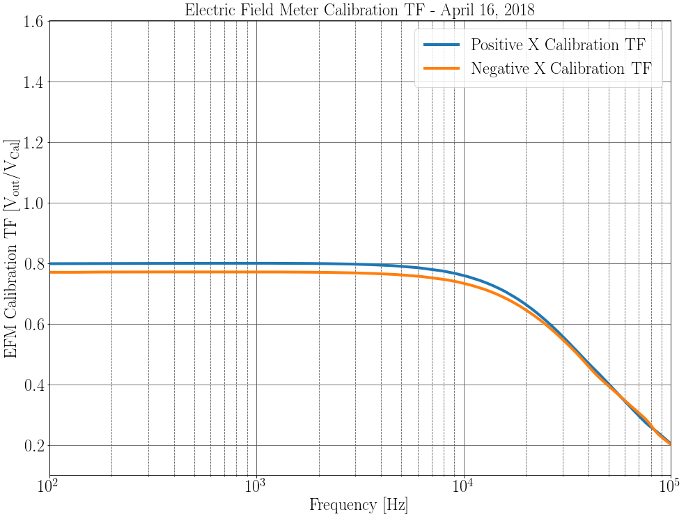
We did not account for this. We did not understand that the EFM body was grounded, so that the body absorbs the E_cal field by inducing charge on its near face. In the presence of a large external electric field both sense plates will have voltage induced, so we will get twice the response from the EFM differential amplifier circuit. We measured a TF from V_cal to V_out where V_out is the voltage output of the EFM differential amplifier circuit, and got V_out/V_cal ~ 0.8 from 5 kHz down. This should be multiplied by 2 for the V_out/V_external TF.Corrected Plots
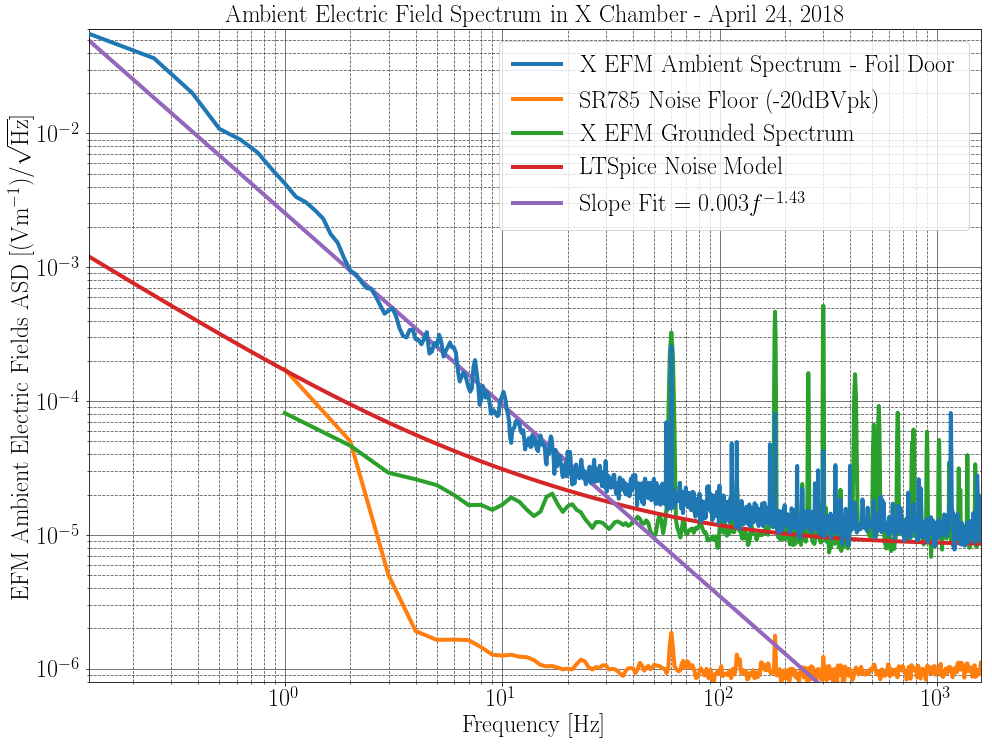
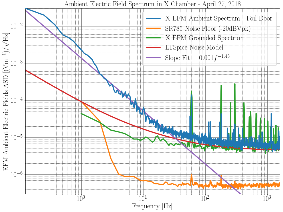
Plot 1 is the newly calibrated ambient electric field ASDs recorded by the EFM. Plot 2 is the V_out/V_cal TF.
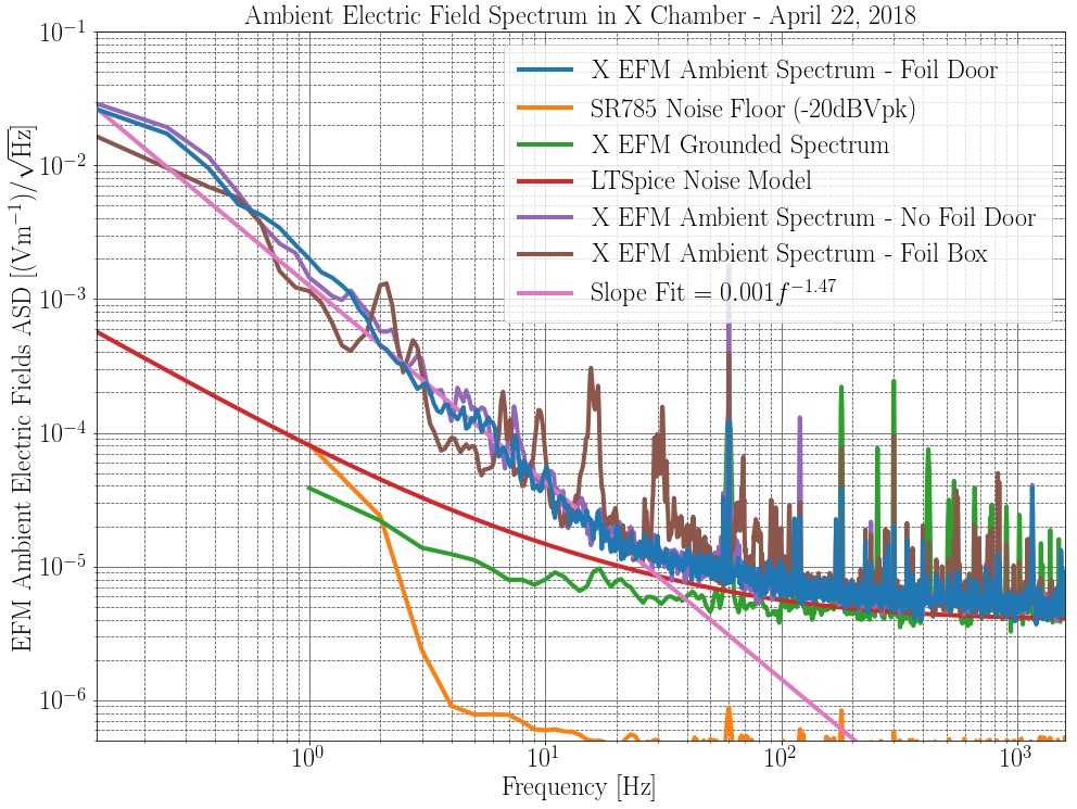
We (the EFM calibration team) never understood that the sensor plates are virtually grounded by the op-amp inside the EFM until we saw Figure 2 of T1700103. This is why we kept insisting that E = Vcal/d should use d = distance between calibration plate and the EFM body: we thought that the sensor plate was an floating conductor. I fixed our calibration to account for the grounded sensor plates. If I use E = Vcal / d where d is the distance between the cal and sensor plates (d ~ 1/2 inch ~ 1.27 cm), I get. If I account for the copper plate and fringing fields by using our measured capacitance between the calibration plate and sensor plate (C ~ 14.7 pF), I get
(Area A of the plates is ~ 0.01 m^2). This is the E/V calibration I used for the plots below. Also included was our cal volts to EFM output volts measured calibration value of 0.8 V/V. This was multiplied by two to account for the differential response of the EFM to external electric fields, and inverted to give
. Unfortunately, with this corrected calibration our prototype EFM spectrum is worse than we originally thought. In fact, it's worse than your final prototype spectrum from T1700569 by about a factor of two. I am not sure why this should be the case. Rich's LT Spice model has a output voltage noise floor of about 200 nV/rtHz at 200 Hz upward. In your Figure 2 of T1700569, you report a Vn of 110 nV/rtHz, so maybe this result is correct.
The calibration is simpler than you make it. With the cube grounded and the calibration plates
mounted on the sense plate, the electric field induced on the sense plate is E = V(cal)/d (with small
correction for fringing and the copper plug). If you want to make a model for the calibration to predict
the sensitivity that is more complicated and requires knowledge of the capacitances and the potentials
between the sense plate and the cube.
Craig, you refer to T1700103 figure 2 to understand the virtual ground. This is not the correct schematic for the implementation of the EFM that was recently built. Each EFM input is simply 10^12 ohms to ground (in parallel with the sense plate capacitance). There is no virtual ground provided actively by the operational amplifier.
Final note on the EFM calibration. Conclusions:After a discussion with Rai and Rich we determined the correct calibration is
where
is the driven voltage on the cal plate,
is the induced voltage on the sense plate, and
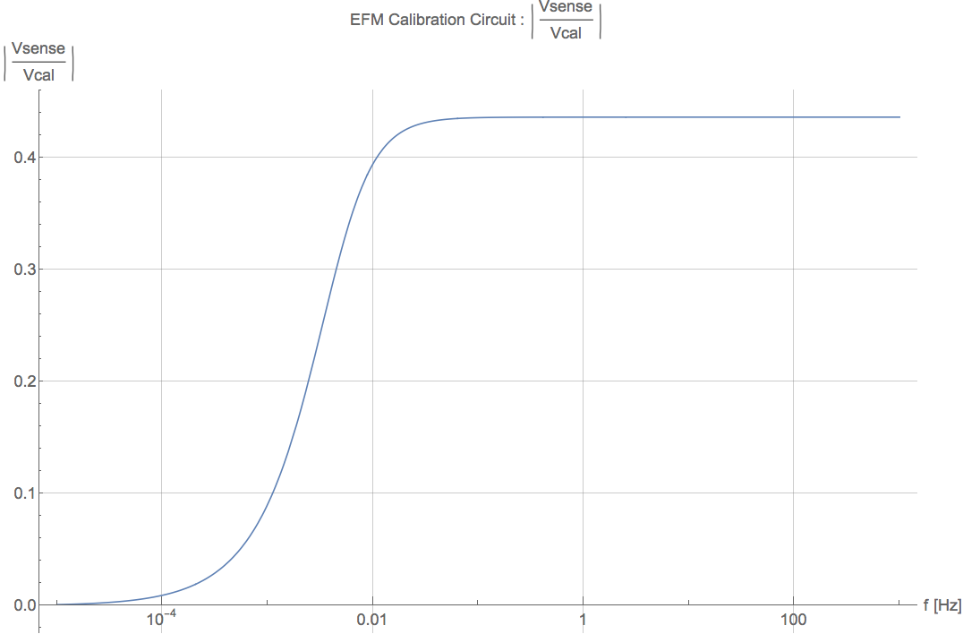
is the distance between cal and sense plate. We need to know the voltage induced on the sense plate. To do this I simulated the circuit in the first picture. Again, we measured the capacitance between the cal and sense plate to be 14.7 pF, while the capacitance between the sense and body was 19 pF. I found
above 10 mHz. Solving for
gives the result above. The final plot is the correctly calibrated ambient electric field spectrum.
I am very sorry for having generated all this confusion. The sense plate is not a virtual ground, that was the case in earlier circuits. In this
circuit the proper formulation for the electric field on the sense plate from the calibration plate is

          V(cal) - V(sp)           V(cal) C(cal-sp)
E(cal) = ---------------- = ----------------------------------  So, the calibration field is smaller than in the case for the sense plate held
            d(cal-sp)       d(cal-sp)(C(cal-sp)+C(sp-allelse))

at ground potential which makes the field meter more sensitive. Which is what you found. The error is purely mine and not Rich Abbott's or any
of the people in the electronics group. It comes from my not thinking about the calibration again after the circuit was changed from one type
to another in my lab.
LIGO-E1800008: ECR: Timing Comparator replace 5V regulator with seperate DC Power board
LIGO-E1200034: Timing RF Counter/Comparator Software Release
LIGO-E1700246: ECR: Add frequency counter channels to timing comparator
One down, three to go!
Reinstalled proper Timing Comparator S1107952 into CER and returned spare to the rack. *Spare still requires upgrade
Pulled, Upgraded and Reinstalled MSR Timing Comparator S1201224.
No front ends were harmed in this operation.
Three Timing Comparators done, one remains unmodified at X end.
