Displaying reports 47201-47220 of 87736.Go to page Start 2357 2358 2359 2360 2361 2362 2363 2364 2365 End
Reports until 08:40, Friday 27 April 2018
LHO VE
chandra.romel@LIGO.ORG - posted 08:40, Friday 27 April 2018 (41713)
CP4 GN2 heater

GN2 flow into CP4 is low:  20-40 scfhx100, with Dewar head pressure still at around 17 psig. I lowered variac from 60% to 58% since temps are hovering around 200C.

H1 IOO (IOO)
cheryl.vorvick@LIGO.ORG - posted 07:06, Friday 27 April 2018 (41712)
IO GigE 2 alignment

I was unsuccessful at finding the transmitted beam with the IO GigE 2 camera.  There are indications on the sensor of 1064 light being present, but only very distorted.  I increased the power in the IO path, and increased the power through the rotation stage, and checked the power at the bottom of the periscope, and it matched the reading on IMC_IN.  I then restored both rotation stages to set the IMC_IN power to 2W.

H1 ISC (CDS, ISC, SQZ, SUS)
keita.kawabe@LIGO.ORG - posted 18:51, Thursday 26 April 2018 - last comment - 09:49, Friday 27 April 2018(41709)
HAM6 ground loop hell (TVo, Jenne, Sheila, Fil, Keita)

Summary:

We checked ground loop of (almost) all ISC and SUS but not SEI cables at racks or SAT amps. Everything was good except ASC_AS_C, OM3, OMC QPDs and ZM1.

ASC_AS_C and OM3 were fixed.

ZM1 is still bad and the problem should be either the in-chamber cable between the feed through and the cable bracket or the connection at the feed through.

OMC QPDs were not fixed, I'm still trying to remember if QPDs were like this in the past.

Details:

The check method we used was to remove cables at the rack, test the connection between pin 13 and the chassis ground, and between pin 13 and the cable shielding. There should be no connection to the chassis ground but there should be to the shielding.

ASC_AS_C problem was the feed through connection, which doesn't make sense, but it was fixed by undoing and reseating the connection at the feed through in chamber.

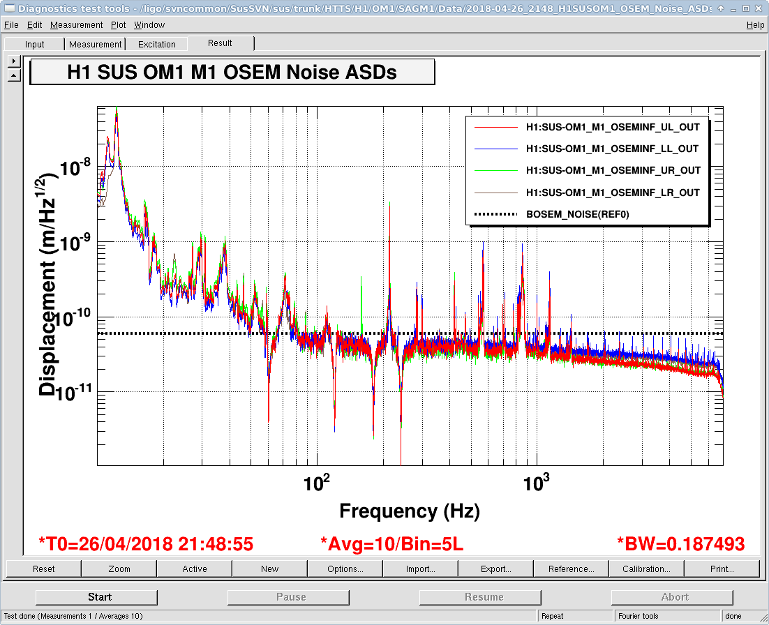
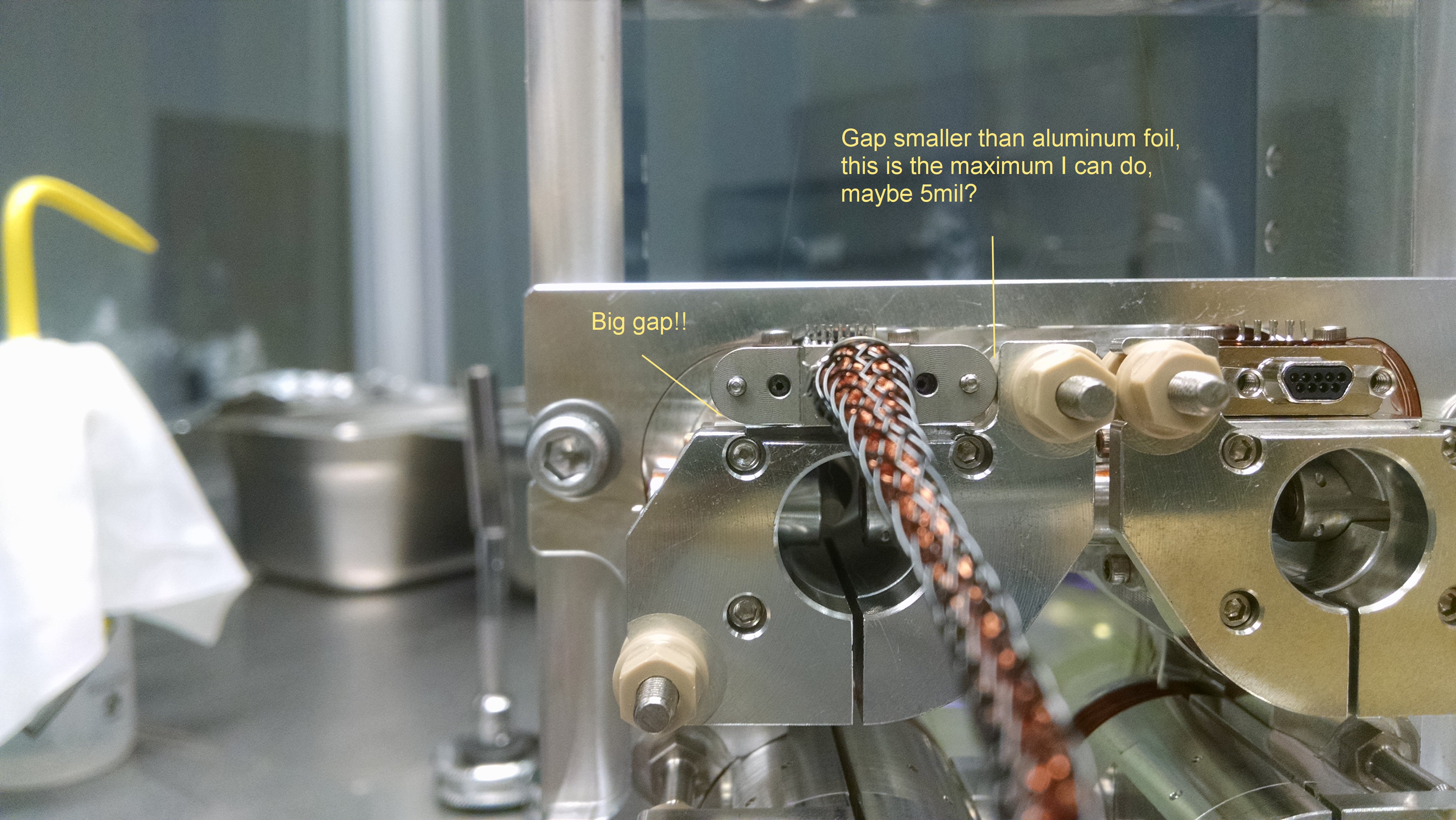
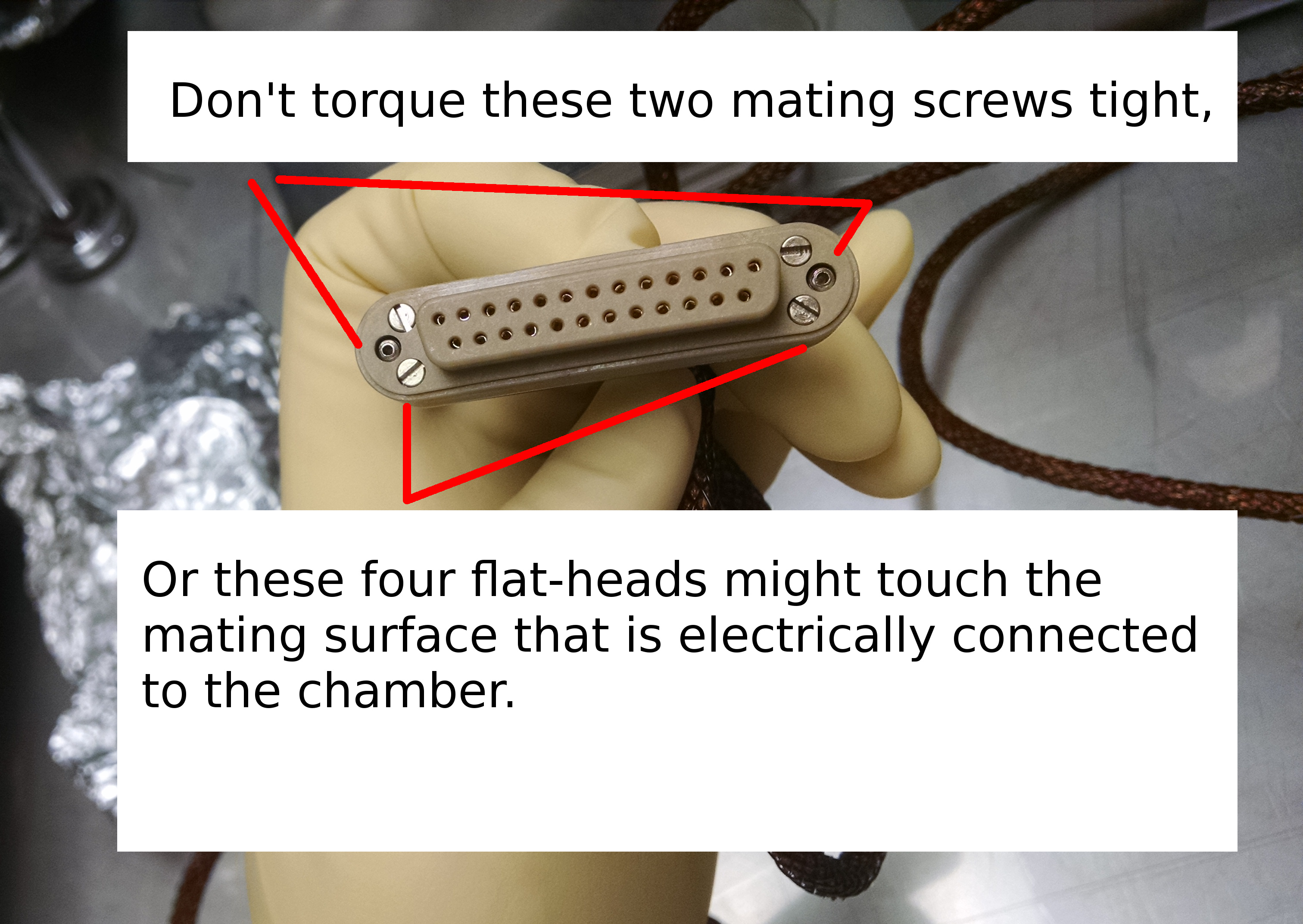
OM3 seems like our old problem (https://alog.ligo-wa.caltech.edu/aLOG/index.php?callRep=12345) where bad design means that the male micro DB connector shell is too close to the surrounding metal. I undid all of the tiny connectors on four OSEMs, reseated and engaged screws again. Each OSEM connector has two screws, and when fully tightened both I got a short. I tried to make the outside screws looser than the inside screws and this seemed to have done the trick. I'm afraid this is just a bad adjustment in an attempt to get a temporary relief. TVo has a picture of the BOSEMs and it seems like there are some spaces between the shell of the connectors and it looks OK-ish.

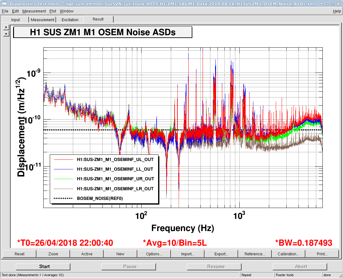
ZM1 is still bad. Disconnecting ZM1 BOSEM cable didn't do anything, so it should be the cable from the feed through to the cable bracket in chamber, or the connection at the feed through just like ASC_AS_C. Problem is that the feed through is at the top of the chamber and it's not easy to reach inside.

OMC QPDs are strange. When OMC DCPD in-air cable is disconnected from the chassis at the same time, there's no connection between OMC QPD in-air cable pin 13 and chassis. However, when OMC DCPD cable is connected, OMC QPD in-air cable pin 13 has a connection to chassis. OTOH, OMC DCPD cable pin 13 is not connected to chassis no matter what.

I'm trying to remember if this is the same thing as https://alog.ligo-wa.caltech.edu/aLOG/index.php?callRep=12349. We checked the continuity between DCPD signal ground (pin15, 16 and 19, 20 of the DCPD cable) and the shield of OMC QPD cable, and of course they're still continuous because it's the design error, but I cannot remember if the symptom we're seeing can be explained by just this. Asking Rich.

Comments related to this report
koji.arai@LIGO.ORG - 20:14, Thursday 26 April 2018 (41710)

Hope this helps...

The short circuit of the chassis and pin13 of the DCQPD happens if the in-air DCPD cable is connected to the whitening chassis

  1. According to "PDF of schematic and layout" (https://dcc.ligo.org/LIGO-D1300520), when the in-air DCPD cable is connected to the chassis of D1300520, the connector shell gets grounded. (See: D1300520 J1)
     
  2. Then if you look at "PDF DCPD Wiring Diagram" (https://dcc.ligo.org/LIGO-D1300502), the shield and the signal gnd are shorted to the shell of the mighty mouse connectors (The signal GND is Pin3 of U18/U23 and the shell of the mighty mouse is connected there at J8 and J10).
     
  3. The DCQPD wiring is found at https://dcc.ligo.org/LIGO-D1300996. The shields of the mighty mouse connectors are connected to the shield of the in-air DB25 cable.

So if you check Pin13 of the disconnected in-air DB25 for the DCQPD (=the shield of the cable), you find the short with the rack chassis (= the signal ground) if the DCPD chain is connected.

When the in-air cable for DCPD is disconnected at the rack, the connection 1) is cut. Therefore, you no longer see the short between the pin13 of the disconnected in-air DB25 for DCQPD and the rack chassis.

----

LHO ALOG 28969 says: "All the OMC cables (OMC DCPDs, OMC QPDs, and OMC PZT) are sharing their shield on the OMC breadboard. Therefore one needs to remove the related three DB25 cables from the flange when the shield shorting is checked for them."


jeffrey.kissel@LIGO.ORG - 09:49, Friday 27 April 2018 (41716)
In-vac cables' backshells grounding against the chamber feedthrough can be followed in IIET Ticket 10037.

BOSEM micro-D's grounding against their brackets can be followed in IIET Ticket 10518.
H1 PSL (PEM)
terra.hardwick@LIGO.ORG - posted 17:18, Thursday 26 April 2018 - last comment - 09:32, Wednesday 02 May 2018(41707)
PSL motion site comparison

Now that both sites are running the 70 W, I've done a quick comparison of the periscope motion and the microphones.

The plot shows PSL periscope accelerometer (top) and mic (bottom) at LLO and LHO. LHO periscope has significantly more motion 20 - 300 Hz and around 1 kHz, though from Jenne's recent look at WFS, looks like the peaks at 350 Hz (PZT mount) and ~600 Hz are what get in as jitter. I recently did a make-up air test at LLO; there's no effect on the per acc at LLO but maybe LHO should do a quick on/off check to see if it couples in at LHO.

The orange lines in the plots show from a day before red, before Peter and Jeff did some noise reduction work, so you can see the improvement orange to red, especially at high freq.

As for microphones, it looks like LHO's is sensor limited and heavily polluted by 60 Hz. PEM runs differential, so maybe something along the way is getting onto the shield? We see this in many of the mics there. Note that LLO has different microphones that have lower sensor noise, but not enough to account for the difference we see now between the sites (the microphone-type difference is included in the calibration).

I took LHO data during the middle of the night 4/24 and 4/25; I'm told the PSL was in science mode and both sites have HAM6 clean rooms running.

Images attached to this report
Comments related to this report
anamaria.effler@LIGO.ORG - 13:13, Friday 27 April 2018 (41721)

The floor motions are very different at the two sites at the moment, looking at the closest floor accelerometers, under HAM1. So some of the extra motion at the periscope might be explained by this (calibration is the same for these two channels, so they are directly comparable).

Images attached to this comment
terra.hardwick@LIGO.ORG - 09:32, Wednesday 02 May 2018 (41790)PEM

Cheryl, Terra

Last week Cheryl turned the PSL makeup air to a few different levels. I've looked at the PSL periscope acc and the microphone (though as previously mentioned, not sure how much info can be gleamed from the mic). LHO PSL makeup air runs at 20% for science mode; Cheryl also tried 10% and 40%. Results show no impact on periscope motion save for slight increase just under 10 Hz - nothing to explain the large difference between the sites' pericope motion at high frequency. LLO makeup air test here.

Images attached to this comment
LHO VE (VE)
gerardo.moreno@LIGO.ORG - posted 17:07, Thursday 26 April 2018 (41554)
HAM6 PT110 Gauge Replaced

Replaced PT110 gauge (Old gauge BPG402) with a new type of guage model number BCG450.  Conflat joint will need to be leak tested.

LHO VE
chandra.romel@LIGO.ORG - posted 17:03, Thursday 26 April 2018 - last comment - 20:22, Monday 30 April 2018(41704)
new NEG activation at EY follow up with full RGA data

This is a follow up to log entry 41558 concerning the activation of a valved-in NEG pump on BSC6 south door at end-Y station and the release of unwanted gases in main vacuum volume.

I compiled RGA scans into one plot in the attached spreadsheet booklet (raw RGA files in zipped folder). In short, the release of gases for the <1 minute the heated pump was valved into main volume quickly recovered and all partial pressures are currently below the baseline recorded last week on April 19.

To recap, we activated for the first time a new type of "high vacuum" NEG pump:  HV1600-10 NexTorr hybrid (includes 10 l/s ion pump behind NEG cartridge) mounted to BSC6 south door, furthest away from test mass (in BSC10) and beam tube (red body in photo). Activation includes heating the pump to 500C for at least one hour, and cooling to nominal operating conditions. In the case of this new type of NEG, the nominal operating temperature is 180C, unlike the other NEGs we use which are not heated in normal operating conditions. The advantage of this ZAO material is that the pump can be activated at pressures as high as e-4 Torr and not saturate as quickly from nitrogen. The NEG pump was valved into main volume for a short period (~ 1 min or less) during the start of activation, until we noticed partial pressures in RGA scan rising. We quickly isolated the NEG and connected an aux turbo cart to its housing to continue activation and pump away unwanted gases.

Total pressure attached, trended from PT-410B, cold cathode pressure gauge mounted to top of BSC10. The pressure before activation was 5e-7 Torr, peaked at 3e-6 Torr during activation (on main volume side, before valving out NEG), and recovered to mid e-7 Torr. The following day we valved NEG back into main volume (its local pressure had dropped to e-9 Torr); pressure fell from 6e-7 Torr to 3e-7 Torr. No change in slope.

EY main volume is being pumped by the main turbo pump following a many month long vent. RGA is Pfeiffer Prisma Plus.

Lesson learned:  VALVE OUT ALL NEG PUMPS DURING ACTIVATION

Images attached to this report
Non-image files attached to this report
Comments related to this report
chandra.romel@LIGO.ORG - 08:49, Friday 27 April 2018 (41714)

RGA settings

Images attached to this comment
rainer.weiss@LIGO.ORG - 13:42, Saturday 28 April 2018 (41732)
What is the torr/ion ampere ratio for this RGA at some popular gas such as amu 28. My guess is the RGA is in Faraday mode
for which the typical ratio is around 1000 to 10000. 

Sorry, I did not see the rga parameter file when I asked this question. It looks like the rga is in sem mode. Is there some idea for the ratio at any one of the
hydrocarbon groups?
chandra.romel@LIGO.ORG - 20:22, Monday 30 April 2018 (41759)

Rai, I'm not sure how valid this is, but adding up all partial pressures (AMU 0-100) gives 3.3e-5 amp; the total pressure reading at that time was 5e-7 Torr, which yields 0.015 Torr/amp. This is a Pfeiffer Prisma Plus model which gives a much different ratio from the SRS models, based on what I've seen with oven bake load data. Kyle has found that typically the water contribution to total pressure is 20%, which would yield ~0.1 Torr/amp. All RGAs have N2 and Kr calibration gases, so I can get an accurate ratio for you at N2 peak.

H1 SEI
hugh.radkins@LIGO.ORG - posted 16:13, Thursday 26 April 2018 (41699)
WHAM SEI Current State in Readiness for close out

WHAM6 ISI has been floated and is Balanced; but, the ISI is currently locked on lockers.  The counterweight payload has been as-built.  ISI Transfer Functions have NOT been run.  We were getting ready to run TFs but ground loops have been found and those are currently being dealt with.  SEI will unlock the ISI and check TFs when the ground loop checks/corrections have completed.  I wiped down the State0 surfaces.

A 1" witness optic has been installed on the +X+Y upright of the OMC--see photo.  The First Contact on the exposed surface will need to be removed.

A 4" wafer witness should be placed in a good/safe place--maybe see Sheila for an ideal location.  These Contamination Control tasks should be done at the latest moment possible before the doors are installed.

Images attached to this report
H1 AOS
edmond.merilh@LIGO.ORG - posted 16:06, Thursday 26 April 2018 (41682)
Shift Summary - Day

TITLE: 04/26 Day Shift: 15:00-23:00 UTC (08:00-16:00 PST), all times posted in UTC
STATE of H1: Planned Engineering
INCOMING OPERATOR: None
SHIFT SUMMARY:
LOG:


15:40 TJ out to HAM6

16:46 Kyle at EY

16:58 Tj back

17:28 Cheryl out to PSL enclosure -camera placements

17:39 Hugh and Corey out to lock ITMY HEPI

17:39 Gerardo out to HAM6

17:40 Marc to MY

17:57 Fil out to HAM6 - killing HV to PZT and Fast Shutter

18:00 Gerardo back

18:30 Hugh and Corey done locking ITMY and moving to ITMX

18:52 Fil out

19:12 Cheryl back

20:43 Corey transitioning LVEA to LASER safe

20:53 Sheila ou to HAM6

20:55 Cheryl out to PSL enclosure

20:56 Fil out to LVEA - ground loop checking with Keita

20:57 Main PSL shutter closed - light from IMC cameras went dark

21:03 Chandra out to MY

21:09 Keita out to HAM6

21:35 Corey back

22:45 Hugh back

23:00 Fil and Cheryl back

23:05 Marc still at vault in desert

H1 SUS
jeffrey.kissel@LIGO.ORG - posted 16:06, Thursday 26 April 2018 - last comment - 21:20, Thursday 26 April 2018(41698)
H1 SUS OPO Ready for Doors
J. Kissel

After a long and arduous journey, we're finally ready to put the brand new H1 SUS OPO suspension under vacuum. All close-out TFs look acceptable, as do spectra of the sensors. All OSEMs are centered. 

SUS is ready for doors.

Non-image files attached to this report
Comments related to this report
lisa.barsotti@LIGO.ORG - 21:20, Thursday 26 April 2018 (41711)

Well done!

H1 SUS (ISC, SQZ, SUS)
jeffrey.kissel@LIGO.ORG - posted 15:14, Thursday 26 April 2018 (41696)
HAM6 H1 SUS HTTS Ready for Doors
J. Kissel, T. Shaffer

TJ scanned over the OMs this morning, looking at and adjusting eddy current damping magnets and earthquake stops on all HTTS in HAM6 -- OM1, OM2, OM3, and ZM1. Then, he took the full suite of transfer functions to confirm all where free of rubbing. They're all free of rubbing.

ZM1 still shows a bit of abnormal dynamics in its yaw to yaw DOF (abnormal w.r.t. to all other HTTSs, showing a second resonance in yaw other that the expected primary mode, and the primary mode is a bit lower in frequency than expected), but it will work well enough.

I've processed TJ's results, and they're attached.

Also, I've checked the OSEM centering -- looks good. 

Also, also, checked the high-frequency spectra -- looks good enough. Interestingly (is it really? do we wanna know? do we care enough to fix it?) ZM1 shows much more lines, junk, and ~6-7 kHz humps where the OMs do not. Fil & CDS crew have yet to perform ground loops checks, so they may identify and fix a problem or two that may alleviate this issue.

Regardless, I decree the HAM6 HTTSs are good enough for us to close doors.
Images attached to this report
Non-image files attached to this report
H1 AWC
alexei.ciobanu@LIGO.ORG - posted 14:45, Thursday 26 April 2018 - last comment - 17:06, Thursday 26 April 2018(41679)
Effects of bowtie astigmatism from OMC on mismatch from OMC scans

Alexei, Dan Brown

The design spec for the OMC has an astigmatic eigenmode. This is generally ignored when analyzing mode scans since the finesse of the OMC is not large enough to resolve the second order peaks of the x/y eigenmodes and they are assumed to be close enough as to basically sit on top of each other.

Recent independent FINESSE models by Dan and I (mine is at the IFOSIM git) have found that the mismatch (as estimated by the ratio of the second order peak to the zeroth order [A2/A0]) is always underestimated by about ~ 18.6% (i.e. a factor of 0.814) for any mismatch we put in.

My current working model is that the small separation between the x and y peaks causes the second order peak to appear smaller and wider than it normally would if the OMC eigenmode was not astigmatic. Therefore in an ideal environment (no misalignments, perfect input gaussian beam) the mismatch computed from an OMC mode scan will ALWAYS UNDERESTIMATE the actual mismatch between the beam and the cavity eigenmode by a constant factor.

Figure 1 demonstrates the effect of what I am talking about. Lx(fwhm,2*delta_fx) and Ly(fwhm,2*delta_fy) are lorentzians (corresponding to a second order resonance) with a fwhm and offset defined by the design OMC parameters.
fwhm = 643943 Hz
delta_fx = 5.813185e+07 Hz (mode spacing of xaxis modes)
delta_fy = 5.797750e+07 Hz (mode spacing of yaxis modes)

The height of the Lx+Ly peak is 18.69% (a factor of 0.814) smaller than the height of 2*Lx (what it would be without astigmatism).

In order to counteract this effect multiplying the measured peak height for the second order peak by 1.23 is sufficient.
This factor can be computed from evaluating the ratio of 2*Lx at its center to  Lx + Ly at the midpoint of their centers by the following equation

(x^2 + 1)

where x = |2*delta_fx - 2*delta_fy| / fwhm.

The complete derivation of this will be posted up on the DCC at some point in the near future.

Please note that this only meant to be a first order approximation to what is going on. This breaks down for tiny mismatches (10^-4 and smaller) as the peak location stops being at the midpoint between Lx and Ly. If the cavity astigmatism or finesse is high enough to resolve the individual axes then this model is also invalid. But in this particular case of the OMC it should hold, and so my recommendation is for future mismatch calculations (the ones that are computed by A2/A0) from OMC scans to be scaled by a factor of 1.23 to avoid underestimating the actual mismatch.

Images attached to this report
Comments related to this report
alexei.ciobanu@LIGO.ORG - 17:06, Thursday 26 April 2018 (41708)

The DCC document containing the full derivation is at T1800191. Comments are welcome.

LHO VE
chandra.romel@LIGO.ORG - posted 14:02, Thursday 26 April 2018 - last comment - 15:44, Thursday 26 April 2018(41695)
EY pressure gauges tripped

Both PT-423 and PT-424 tripped and have been reset. Expect alarms until cold cathode comes back on.

Comments related to this report
chandra.romel@LIGO.ORG - 15:44, Thursday 26 April 2018 (41697)

Gauges tripped again, including PT-410 this time. This is due to APS contractor work installing security system. FRS tickets filed.

H1 IOO
jenne.driggers@LIGO.ORG - posted 11:55, Thursday 26 April 2018 - last comment - 11:49, Friday 27 April 2018(41688)
Beam jitter as seen by IMC WFS

PeterF pointed out that it would be good to see what beam jitter the IMC WFS are seeing now that we have the new 70W laser operating with the lower water flow. 

I attach 2 screenshots: one of all the WFS, and one with just WFS_B traces, since that has historically and is still the sensor that sees the jitter motion the best.  You can see that the coherence between the WFS and the PEM accelerometer on the PSL periscope has decreased, as well as just the overall spectra.  There is a small new feature at about 583 Hz, but otherwise the spectra above 100 Hz are all notably better.  I haven't confirmed the source of extra low freq noise in the WFS right now, but there's a lot going on in the LVEA, and the comparison time is Observation mode.

Perhaps I'll ask one of our Fellows who is working on the noise budget to use the old coupling TF to try to project what this noise would mean for our O2 DARM, but hopefully we'll also have significantly less coupling now that we've replaced ITMX, so that projection would be an upper limit.

EDIT: Note that these are the RF channels (I just realized that I forgot to include that information in my DTT-froze-on-me / redo things fiasco).  I'll soon post a version with the calibrated WFS DC channels.

Images attached to this report
Comments related to this report
jenne.driggers@LIGO.ORG - 11:49, Friday 27 April 2018 (41719)

Really what we want to see is the WFS DC spectra, in calibrated units so that we can see the ratio of 1,0 modes to 0,0 modes.  However, the times recently that the IMC has been locked have either been at such a low power (0.9W or less), or when the beam was very far off center from the WFS that the data isn't great.

I have some data from a lock on April 4th with the new 70W amplifier but before the rotation stage was locked out at low power (and before the PMC and EOM were swapped), so the IMC was locked with 5.2W injected into the vacuum.  Comparing with alog 34845 from March 2017, some of the peaks look perhaps a little better, but I need to retake the data with the IMC locked at higher input power to have better SNR.  I don't have the unlocked version of WFS at this time - we went straight from locked to laser safe. 

Images attached to this comment
H1 ISC
keita.kawabe@LIGO.ORG - posted 19:39, Thursday 12 June 2014 - last comment - 09:48, Friday 27 April 2018(12345)
HAM6 today

We've eliminated all ground loops that  can be easily eliminated in chamber at this point. There are two remaining grounding-related issues.

  1. There seems to be a serious ground loop problem for OMC DCPD and OMC QPDs, which is described in a separate alog (https://alog.ligo-wa.caltech.edu/aLOG/index.php?callRep=12349).
  2. Shield for beam diverter cables (there are two) appear to be grounded to the ISI via mighty mouse connector. This is Beckhof and there's no signal that needs a great S/N or anything on these cables, and I don't know how the grounding of Beckhof chassis is done, but we might want to modify the in-air DB25 cable to cut the pin13 wire at the feed through.

The first problem will NOT be addressed until I hear back from Rich.

The second issue is dealt with in air (if the solution is to cut pin13 wire).

We "fixed" another tiptilt with more annoying problem than yesterday (see below).

We "fixed" a bunch of other things by changing four in-vac cables (also see below).

Apart from the issues noted above, we checked picos, OMC REFL QPD (sled), AS_C QPD, WFS(DC) and OMC SUS, and these are all good.

Everything is connected back except the DCPD and OMC QPD cables at the field rack.

We didn't like the way a big coil of cables was dangling from ISI table top to the side, no idea why this was done (just an extra weight without real merit), so we moved it to downstairs. Due to the reduced weight on the ISI, Hugh might want to rebalance ISI.

Tomorrow I'll be out, but Corey and Dan will have to do the following:

  1. Re-center BOSEMs of TT2 and TT3. These are the units that we pulled and reinstalled. Most of the coils are OK, but one of the upper coils for each TT is not well centered.
  2. Check if QPDs, WFS(DC) and DCPDs work using a flash light, because we messed with the cables. There are 5 QPDs, 2 WFSs  and 2 DCPDs. Right now all corner station ISC whitening are crazy, ask Daniel to fix before you go in chamber. You also need to connect the DCPD cable and OMC QPD cable back to the field rack.
  3. Check if beam diverters and picos work, because we messed with the cables.
  4. Unlock ISI and give it to Hugh.

After this I don't have a problem closing HAM6 for now.

Comments related to this report
keita.kawabe@LIGO.ORG - 20:01, Thursday 12 June 2014 (12346)

Annoying TipTilt, part 2

When "fixing" OM3, one of the BOSEMs was really persistent. Both the side and the bottom were touching (first picture), and the bottom gap was non-existent no matter what, plus the maximum side gap I was able to achieve was less than the thickness of aluminum foil.

I used a folded piece of aluminum foil as a shim to raise the micro DB connector (second attachment) to have enough bottom gap, and cocked the connector as much as I can to maximize the side gap (third attachment).

FYI, the shell of the female connector in the second picture is not isolated by design. But the male connector shell that is on the cable on the first and the third picture should be isolated.

Images attached to this comment
keita.kawabe@LIGO.ORG - 21:02, Thursday 12 June 2014 (12348)

Annoying cable and connector problem.

We replaced total of four in-vac cables.

Three of them is due to an issue with yet another design feature to rely on razor-thin gap.

In the attached picture, the front shell is PEEK but the screws that fix the front shell to the metal back shell are metal. The screw heads should be somewhat recessed, but if they are sticking out for any reason, they will contact with the metal part of the feed through, thus the metal back shell is connected to the chamber.

Some of the screws are recessed less than the others, and some of them are sticking out because of the screw head slot was somewhat deformed by the screw drivers or whatever. There can be three modes of failure:

  1. Shell touches the chamber when the cable is fully seated and this cannot be fixed without changing the cable or by NOT fully seating the cable.
  2. Shell touches the chamber when the cable is fully seated, but this is due to the fact that the screws are loose.
  3. Shell doesn't touch the chamber by merely fully seating, but it touches as soon as you tighten the connector mating screws tight.

We have identified three cables that were either 1. or 3., and replaced them with new ones which worked OK. There's no reason these screws should be really tight (I think we need to discourage people to do that), but if it fails because the screws are a bit tight, that's not a good cable either.

  Bad New, good
OMC SUS 1 S1????831 S1105029
OMC SUS 2 S1????791 S1105031
OMC DCPD S1??????? S1105035

We identified another cable that was 3., but this was a picomotor cable with thicker gauge wires, and we don't have replacements. Corey made it such that the connector doesn't fully seat (or maybe he just didn't fully tighten the connector, I don't remember). This cable was tested good yesterday and today, but it turned bad when we were doing some other unrelated work at the feed through and its vicinity.

  Bad but in use with a hack
QPD sled Picos S1???????

We also found one cable that makes or breaks ground loop depending on where/how we route and how we breathe, and replaced that with a new one:

  Bad New. gppd
OMC REFL QPD (sled) S1??????? S1105031

The serial number markes as ?????? is not unknown, it was recorded before by Corey, it's just that I don't remember.

Images attached to this comment
corey.gray@LIGO.ORG - 11:33, Friday 11 July 2014 (12528)

Closing the documentation loop on these guys (also updating ICS Assembly Load #ASSY-D1300122-LHO).  I'll mark the damaged cables as such in ICS as well.

  Bad New, good
OMC SUS 1 S1106831 S1105029
OMC SUS 2 S1106791 S1105031
OMC DCPD S1106784 S1105035


  Bad but in use with a hack
QPD sled Picos S1202641 (most likely)

According to ICS, this cable (the elusive D1000223) is most likely one of these:  S1202641 (most likely) or S1202643.  And as Keita mentions, we have no spares of these at LHO (and NONE for 3IFO!). :(


  Bad New. gppd
OMC REFL QPD (sled) S1106780 S1105031
jeffrey.kissel@LIGO.ORG - 09:48, Friday 27 April 2018 (41715)CDS, SUS, SYS
In-vac cables' backshells grounding against the chamber feedthrough can be followed in IIET Ticket 10037.

BOSEM micro-D's grounding against their brackets can be followed in IIET Ticket 10518.
Displaying reports 47201-47220 of 87736.Go to page Start 2357 2358 2359 2360 2361 2362 2363 2364 2365 End