After finally resolving the seg fault issues in guardian (report in full to follow), guardian has been upgraded site-wide and moved to the new production guardctrl host, "h1guardian1".
We've been monitoring the system for the last couple of days and it seems to be working nominally and not showing signs of excess load on the guardian machine. We have seen no seg faults with this new version.
new guardian version: 1.2.0
Other than the fix for the seg faults, which turned out to be because pcaspy is not thread safe, there aren't too many changes in this version that users should notice. The main new features have to do with the node management interface:
- Ability to use NodeManager to request states of subortinates without setting them to MANAGED mode (i.e. without issuing a set_managed command). This enables a "loose" management whereby one node can request a state of another node, without putting it in to MANAGED mode, and without having to deal with stalls on jump.
- Allow for mulitiple NodeManager objects. This is useful if you want to do a mix of loose and micro management.
- Warnings if formatting is incorrect (e.g. mixing spaces and tabs)
Other than that there are just various bug fixes and minor improvements.
new guardian machine, node process supervision
The new production guardian machine is h1guardian1, which is running Debian 9 with all needed software installed from packages from CDSSoft.
Guardian process supervision on h1guardian1 is now handled by systemd. In particular, it's handled via systemd --user under the "guardian" user account.
The load on this machine seems pretty good:
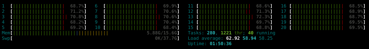
The above is while running all 124 of the H1 nodes. We'll be monitoring this to make sure load average stays below 100.
Note: this is mostly of no consequence to users, as they'll continue to interact with the supervision system via the guardctrl interface, which has been updated to work with the new system...
new guardctrl interface
The new systemd supervision infrastructure required a new version of guardctrl, which is now installed on all workstations. It works mostly the same as the old version, with some slight changes in some of the subcommands:
jameson.rollins@zotws6:~ 0$ guardctrl -h
usage: guardctrl [-h] [-d] ...

Guardian daemon supervision control interface.

Control guardian daemon processes managed by the site systemd
supervision system.

optional arguments:
  -h, --help   show this help message and exit
  -d, --debug  print debug information to stderr

Commands:
    help       show command help
    list       list nodes and node subervision state
    status     print node service status
    enable     enable nodes
    start      start nodes
    restart    restart nodes
    stop       stop nodes
    disable    disable nodes
    log        view node logs

Add '-h' after individual commands for command help.

Node names may be specified with wildcard/globbing, e.g. 'SUS_*'.
A single '*' will act on all configured nodes (where appropriate).
jameson.rollins@zotws6:~ 0$
Known issues:
- Searching through old logs is currently not working. This will be fixed in a new minor release soon.
- Logs sometimes take a few seconds to show up. Still investigating how to make log retrieval snappier.
code archiving temporarily disabled
Guardian node code arching has been temporarily disabled until we're fully confident in the new system. This is because of ownership of the code archives that will need to be moved to the new guardian user. If things are still looking good by next week we will enable the code archives then.
old guardctrl host h1guardian0 still available in case of emergency
If for any reason there are problems with the new setup, we can easily restore everything to the old configuration on h1guardian0. The new guardctrl interface is backwards compatible with the old h1guardian0 host.
The procedure to restore a single node to the old host would be something like this:
$ guardctrl stop NODE_NAME
$ GUARDCTRL_HOST=h1guardian0 guardctrl start NODE_NAME
To do the same for all nodes, replace "NODE_NAME" with "'*'".
NOTE: if all nodes are moved back to the old host, the CDS admins would need to update the DNS record for "h1guardian" to point to "h1guardian0" instead of "h1guardian1".