TITLE: 04/04 Day Shift: 15:00-23:00 UTC (08:00-16:00 PST), all times posted in UTC
STATE of H1: Planned Engineering
INCOMING OPERATOR: None
LOG:
14:39 (7:39) Tyler, Mark to EY
15:00 (8:00) Start of shift
15:15 (8:15) Bartlett to EX -- reset dust monitor #2
15:39 (8:39) Bartlett leaving EX
15:59 (8:59) Chris to EY -- delivering bolt
16:05 (9:05) Tyler, Mark back from EY
16:14 (9:14) Peter and Fil transitioning to laser safe
16:31 (9:31) Gerardo to EY -- vacuum work
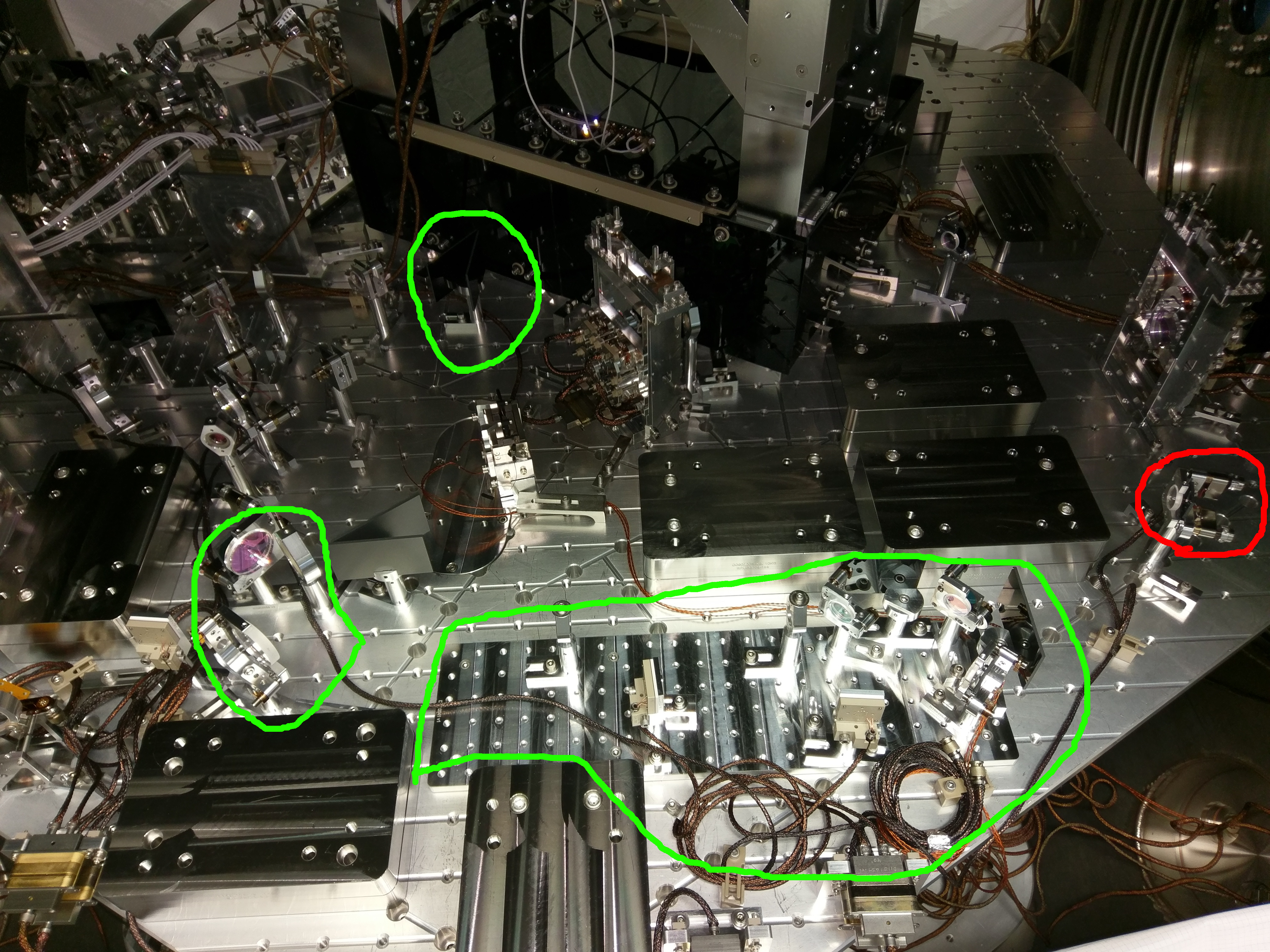
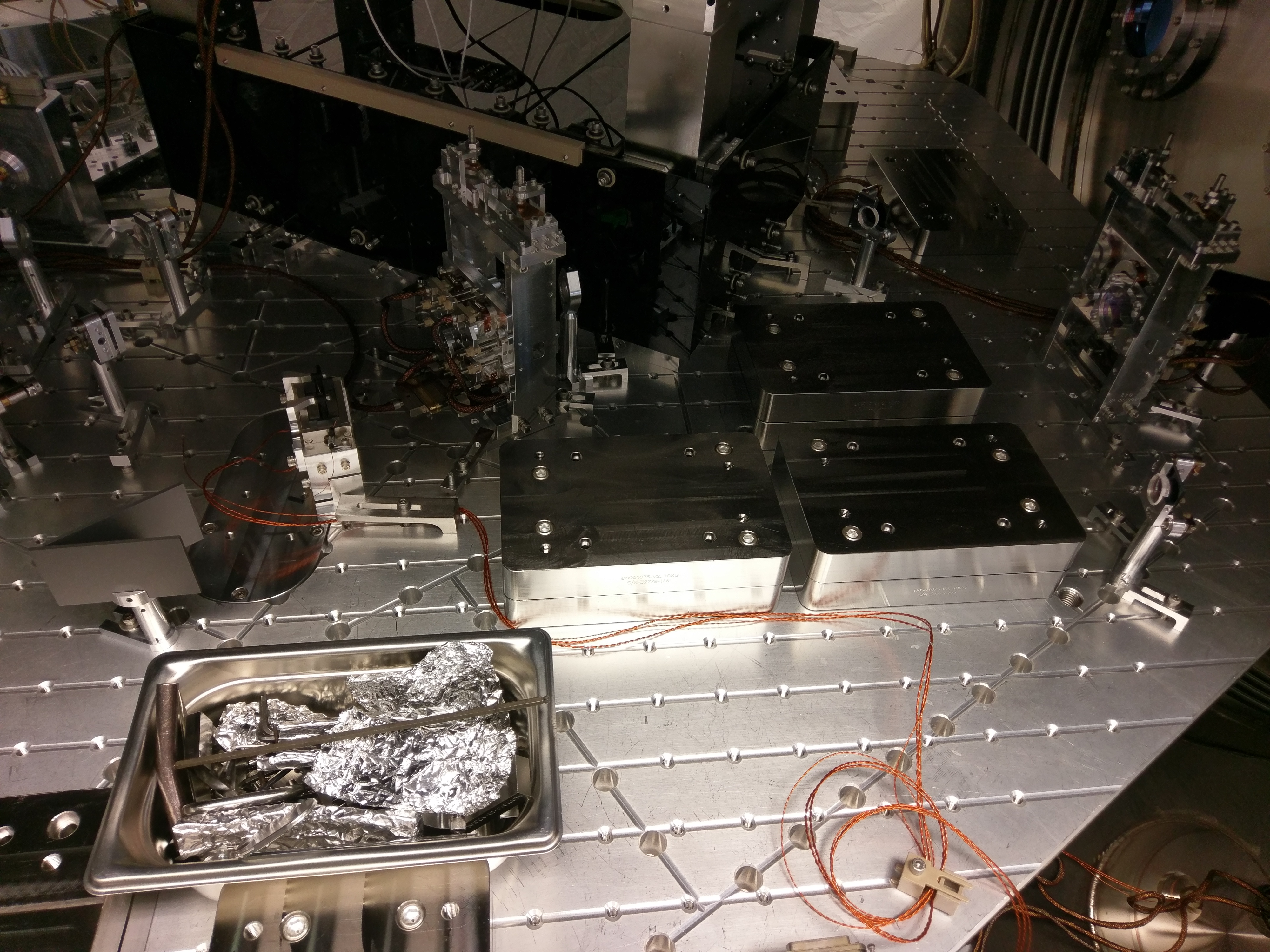
18:14 (11:14) TVo, Sebastien, Dan, Alexei to LVEA
18:39 (11:39) Gerardo back from EY
19:02 (12:02) Gerardo to LVEA
19:29 (12:29) Fil to ISCT6 -- collect GIGE cameras
19:57 (12:57) TVo, Sebastien, Dan, Alexei out of LVEA
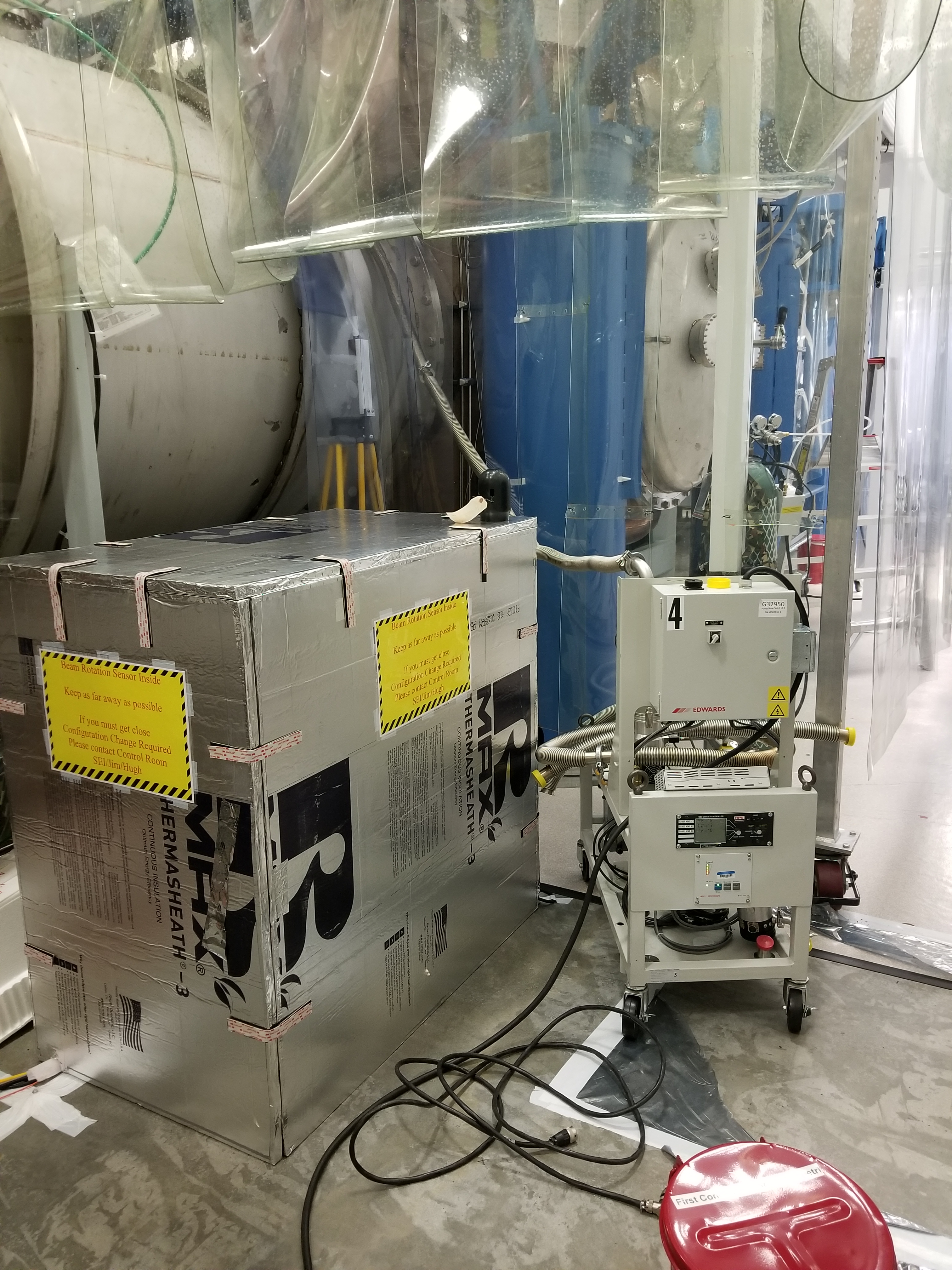
20:19 (13:19) TJ to HAM5 -- cleaning up
20:39 (13:39) Chandra, Tyler to LVEA -- craning work
20:43 (13:43) Gerardo to IP5
20:46 (13:46) Betsy to LVEA -- find something for Livingston
20:48 (13:48) Elizabeth to LVEA
21:02 (14:02) Jason to PSL enclosure -- grab materials
21:03 (14:03) Betsy out of LVEA
21:20 (14:20) TJ out from HAM5
21:29 (14:29) Jason out of PSL enclosure
21:37 (14:37) Elizabeth out of LVEA
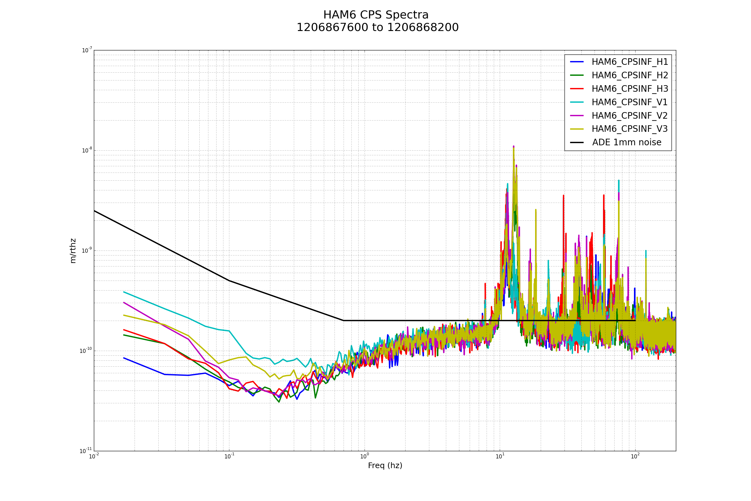
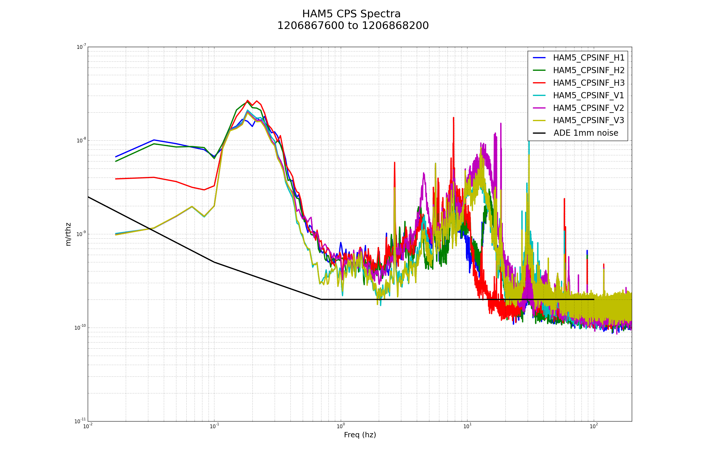
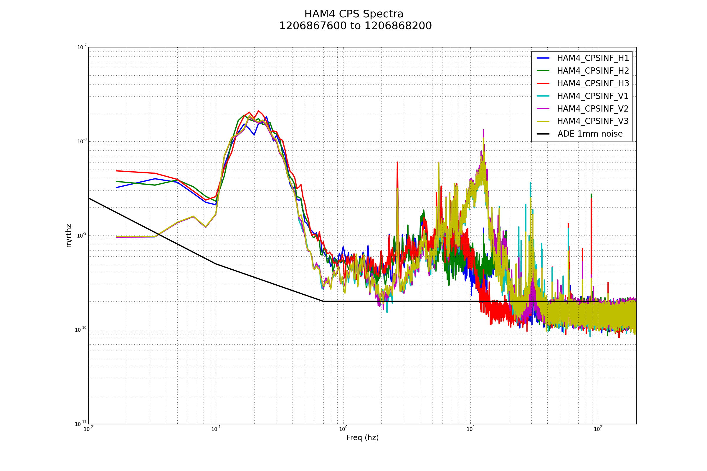
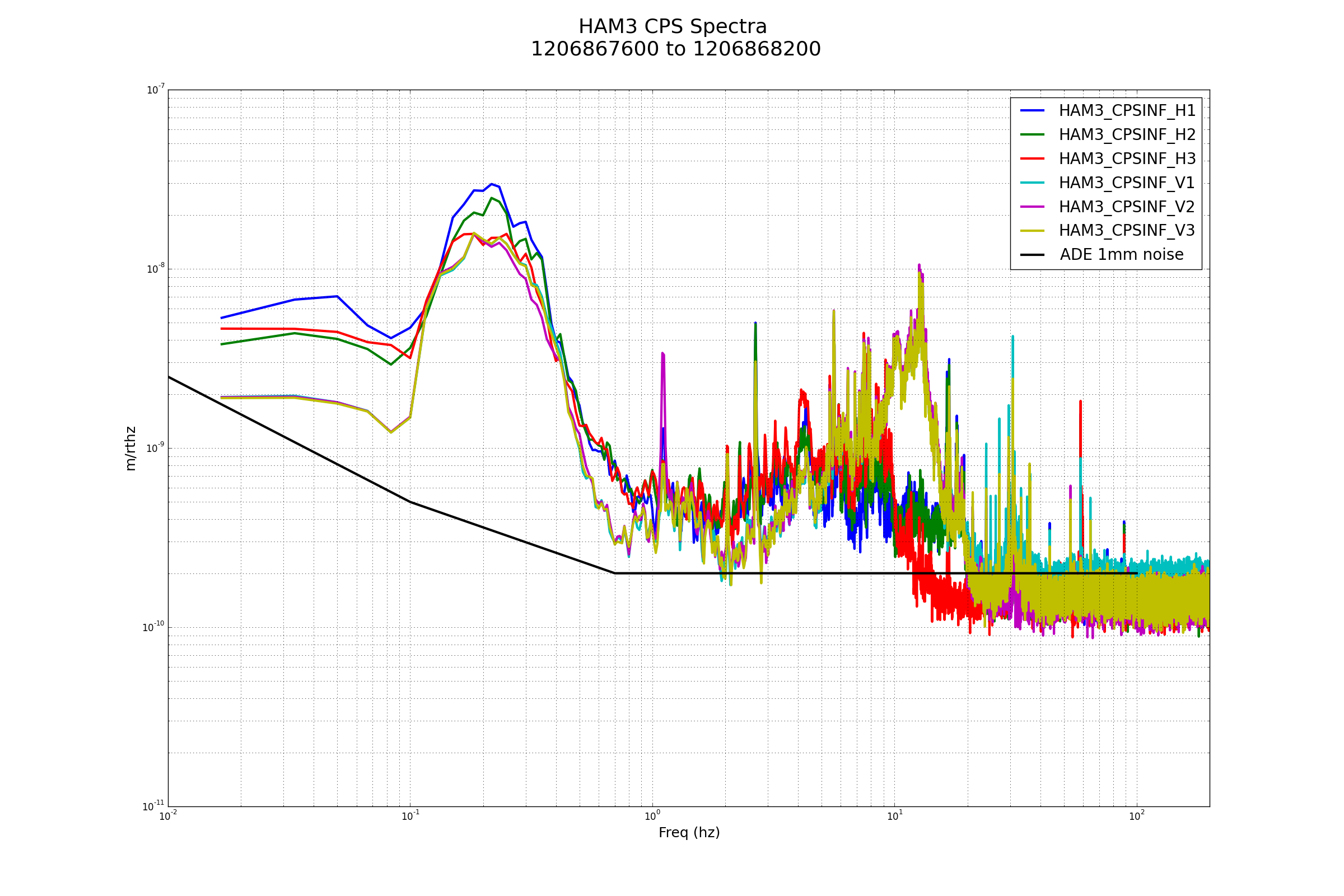
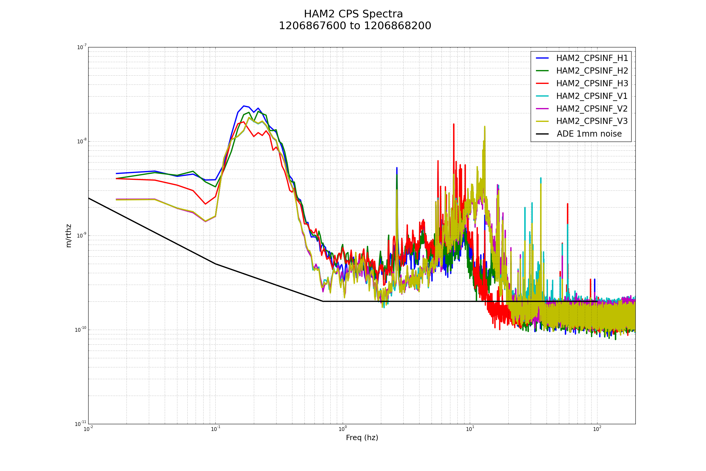
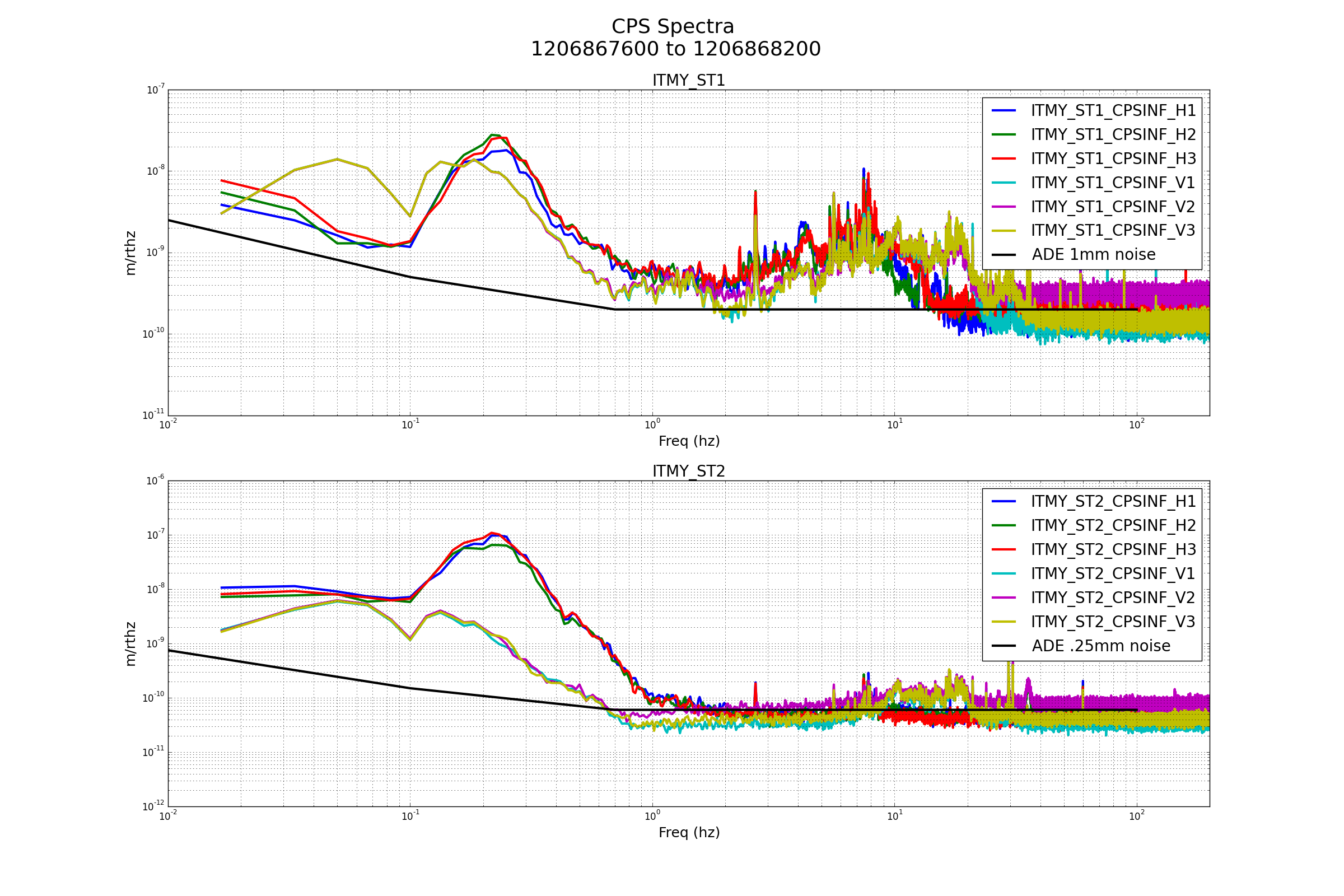
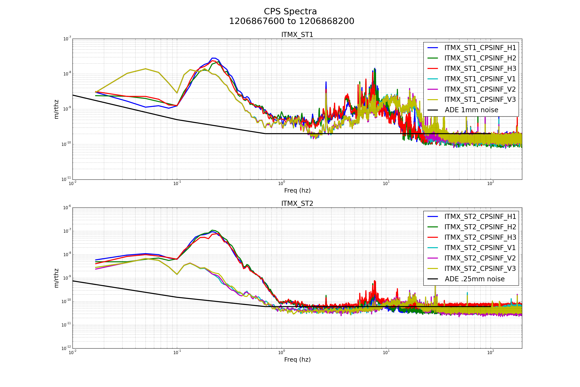
22:01 (15:01) Betsy to LVEA -- investigate HAM5 HEPI
22:26 (15:26) Tyler out of LVEA
22:38 (15:38) Mark out of LVEA -- finished moving forklift
23:00 (16:00) End of shift