I have cleaned up the ISC guardian code (ISC_LOCK, ISC_DRMI, OMC_LOCK, ALIGN_IFO, ALS_XARM, ALS_YARM, ALS_COMM, ALS_DIFF, ISC_GEN_STATES, ISC_library and lscparams).
My goals were to remove depricated code (it's been growing since ~2014, and many functions clearly haven't been used since about then), merge nearly-identical functions (we don't need 15 different functions to determine if a cavity is locked), ensure that functions from sub-files (eg. ISC_library) are clearly called out (by removing all "from _______ import *", which Sheila had already done a lot of work toward), and make the code generally easier to read.
I was going to do a bit more syntax checking, but since we have IR light into the vacuum earlier than had been anticipated and several people have been working on locking the IMC, I deployed the new code this afternoon. All guardians were checked in before I did anything, and then I copied over my files from a side folder into the main userapps guardian folders.
So far, the IMC guardian is able to lock the IMC (after a few boost changes from Sheila, TVo, DanielBrown and Alexei...they'll write a separate alog). The ALIGN_IFO guardian is able to change the SUS configurations, although it hasn't been tested farther than that, since PeterK is working on the PSL.
This cleanup has removed ~4,000 lines of unnecessary guardian user code. I think it'll help make things easier as we go forward with a new commissioning phase.


ResourceSpace collection to be populated - Note that I am working through some issues uploading to ResourceSpace.
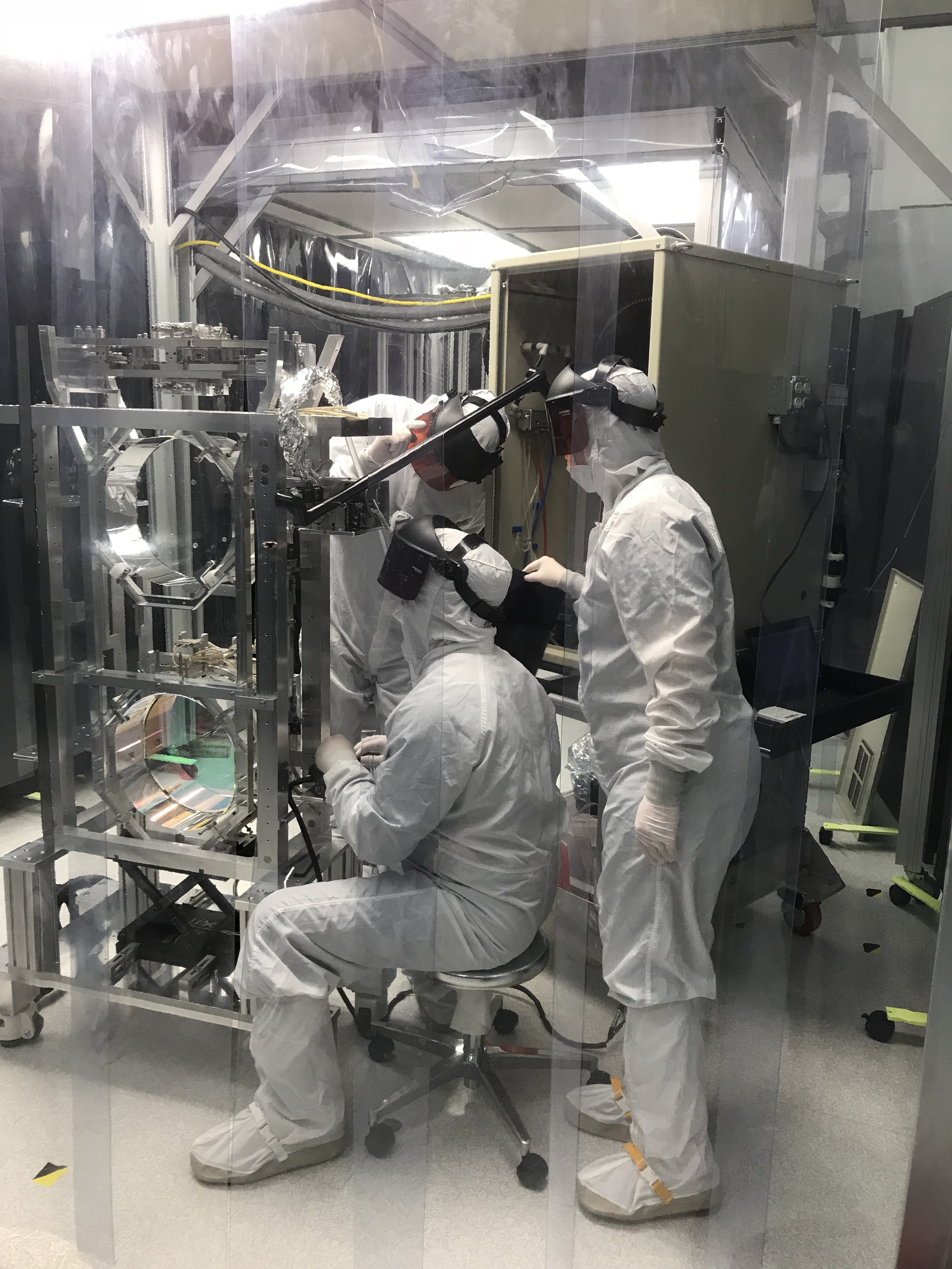
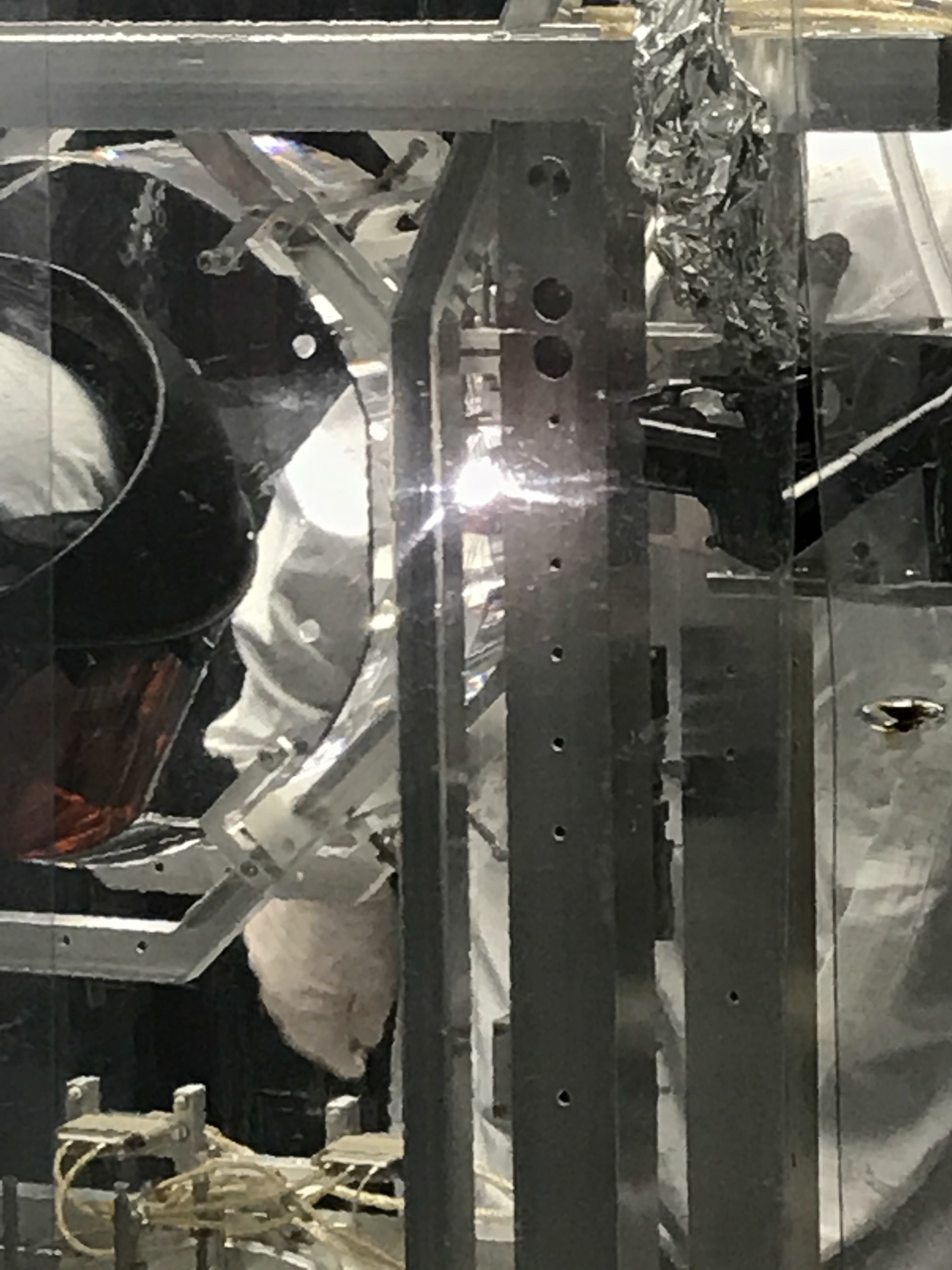
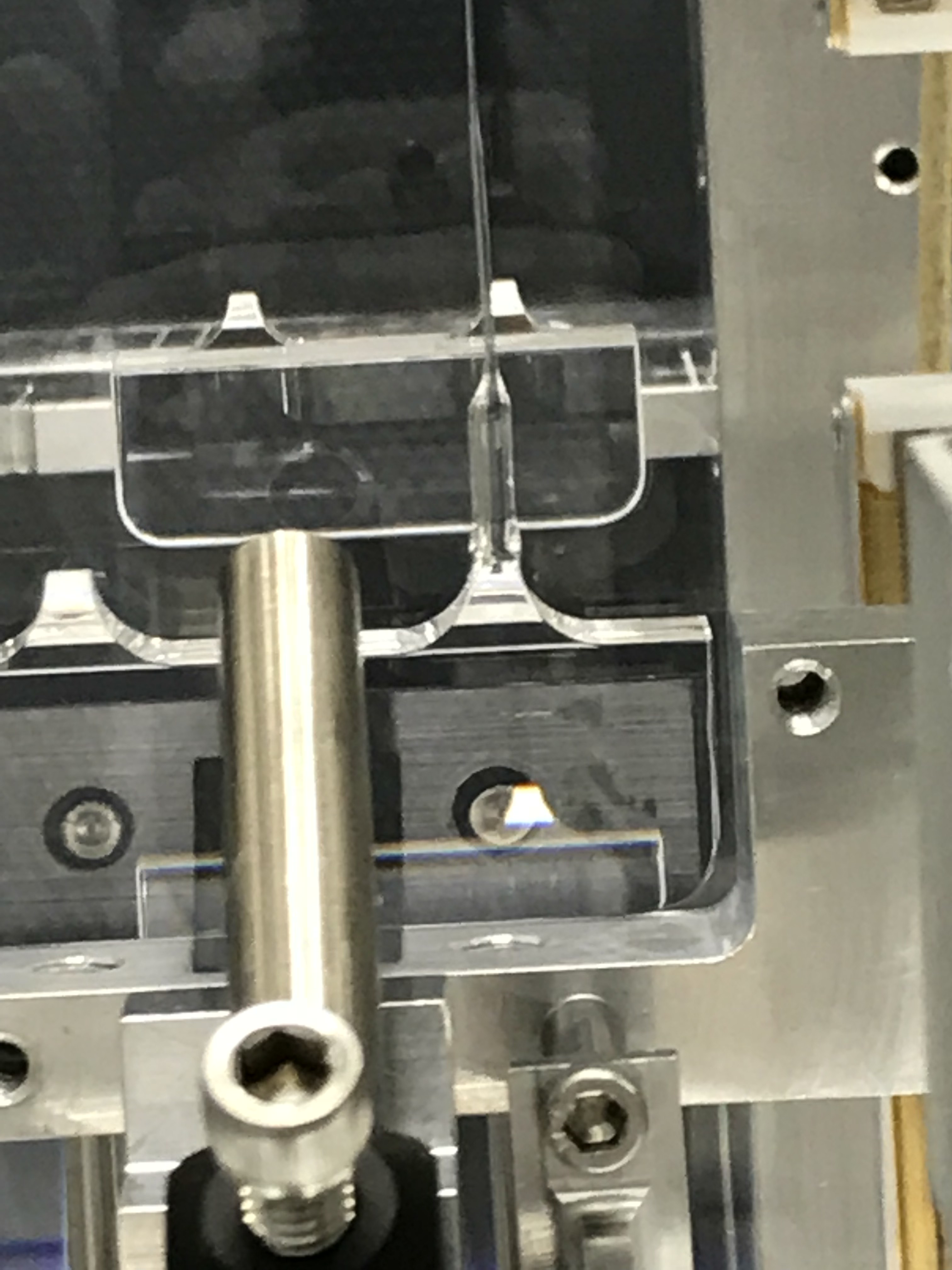
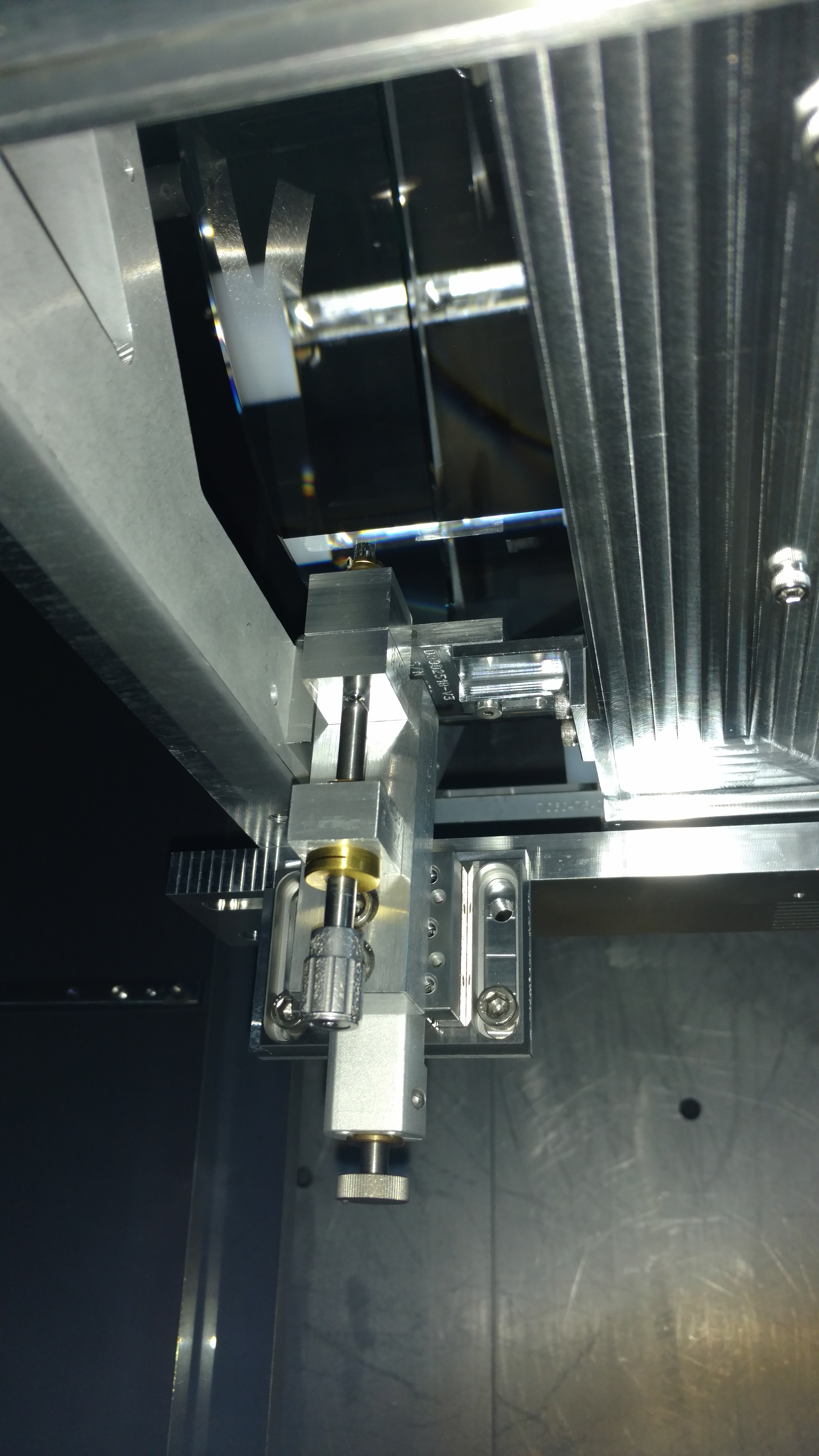
See ResourceSpace for all photos from the effort, plus a few neat videos of welding, annealing, and loading the fibers of ETMx.
Until ResourceSpace gets up and running, I have added the welding/annealing/loading videos to this Box folder (should be accessible with access.caltech login) https://caltech.app.box.com/folder/48265585793