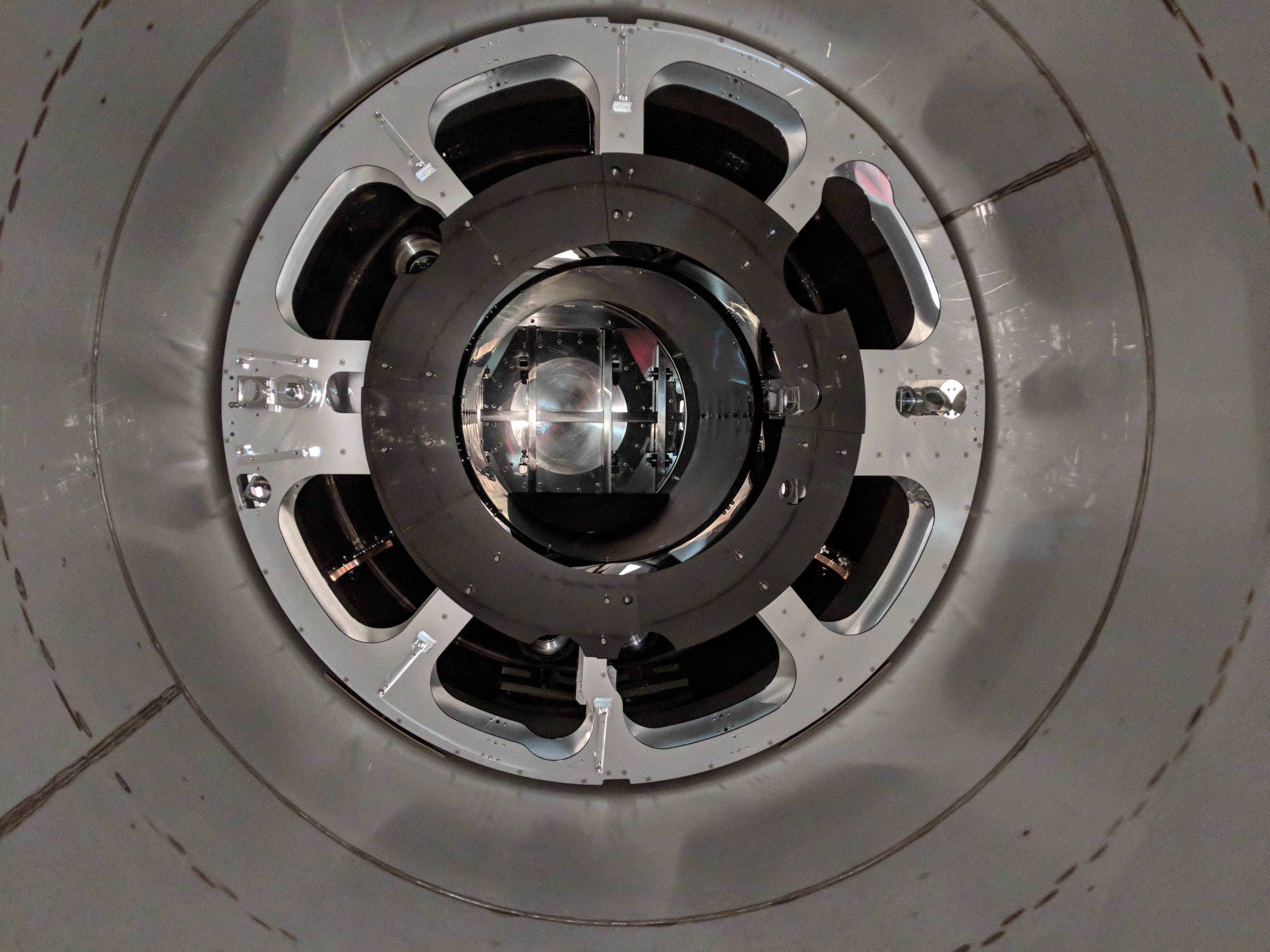
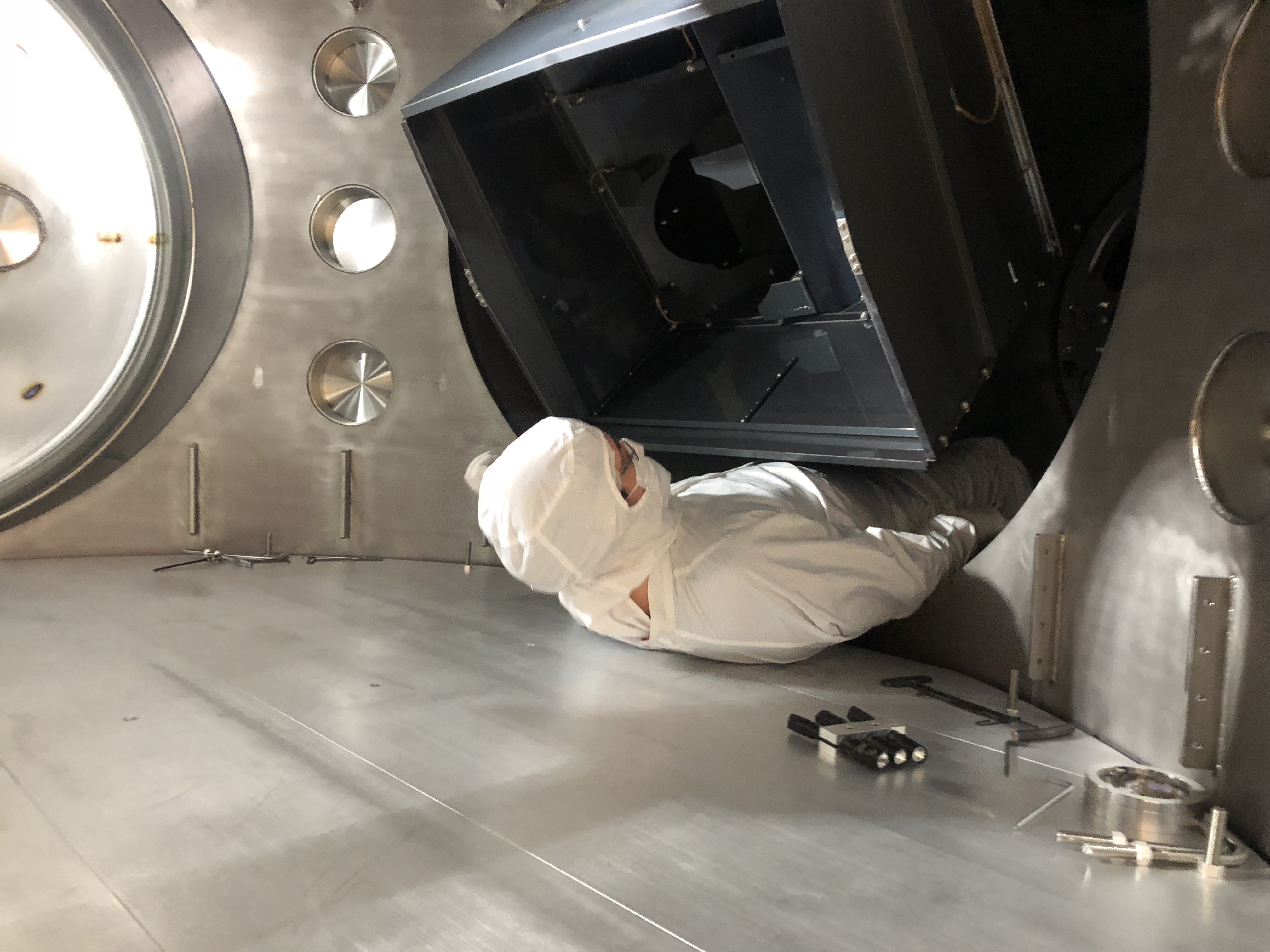
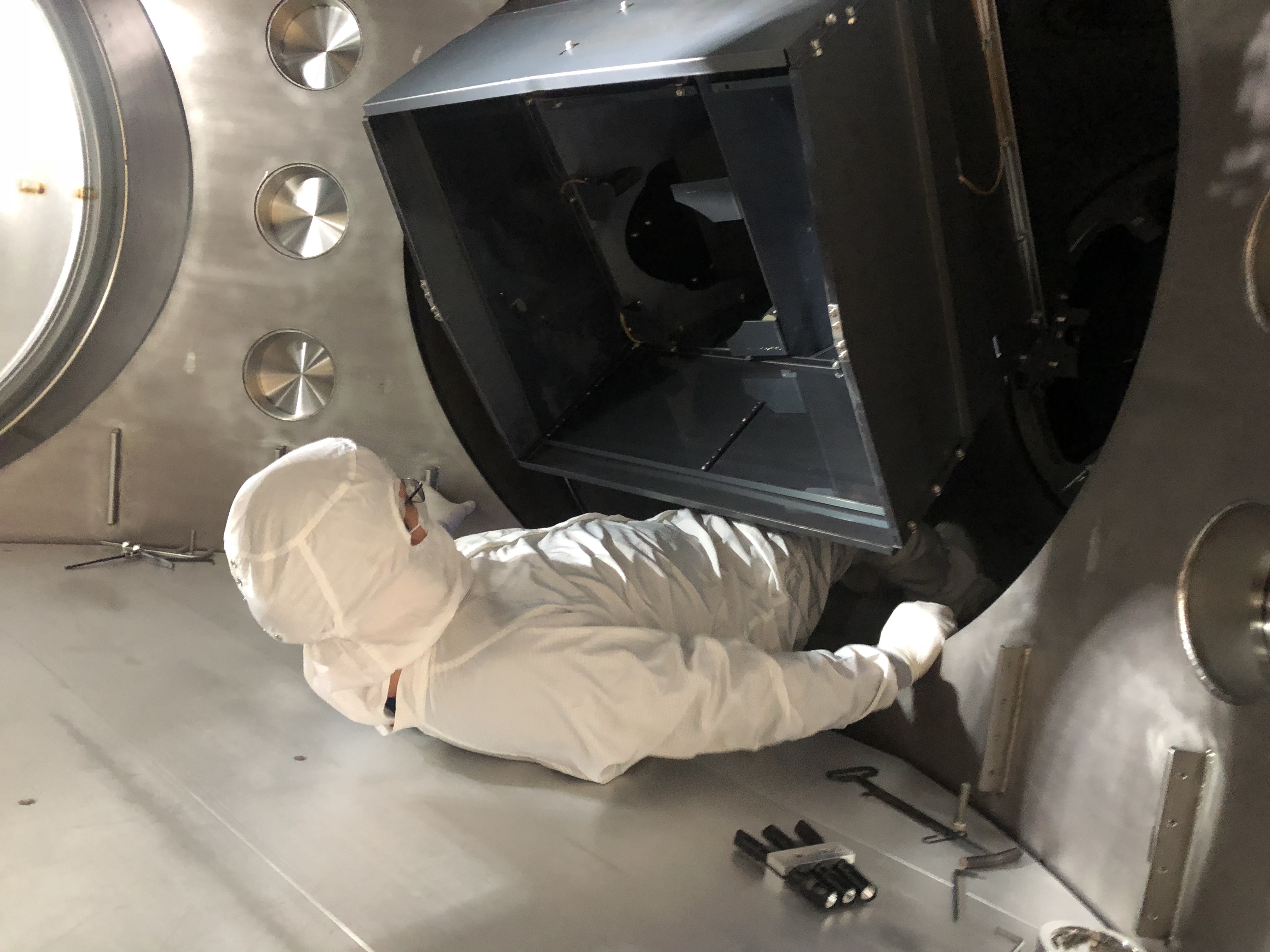
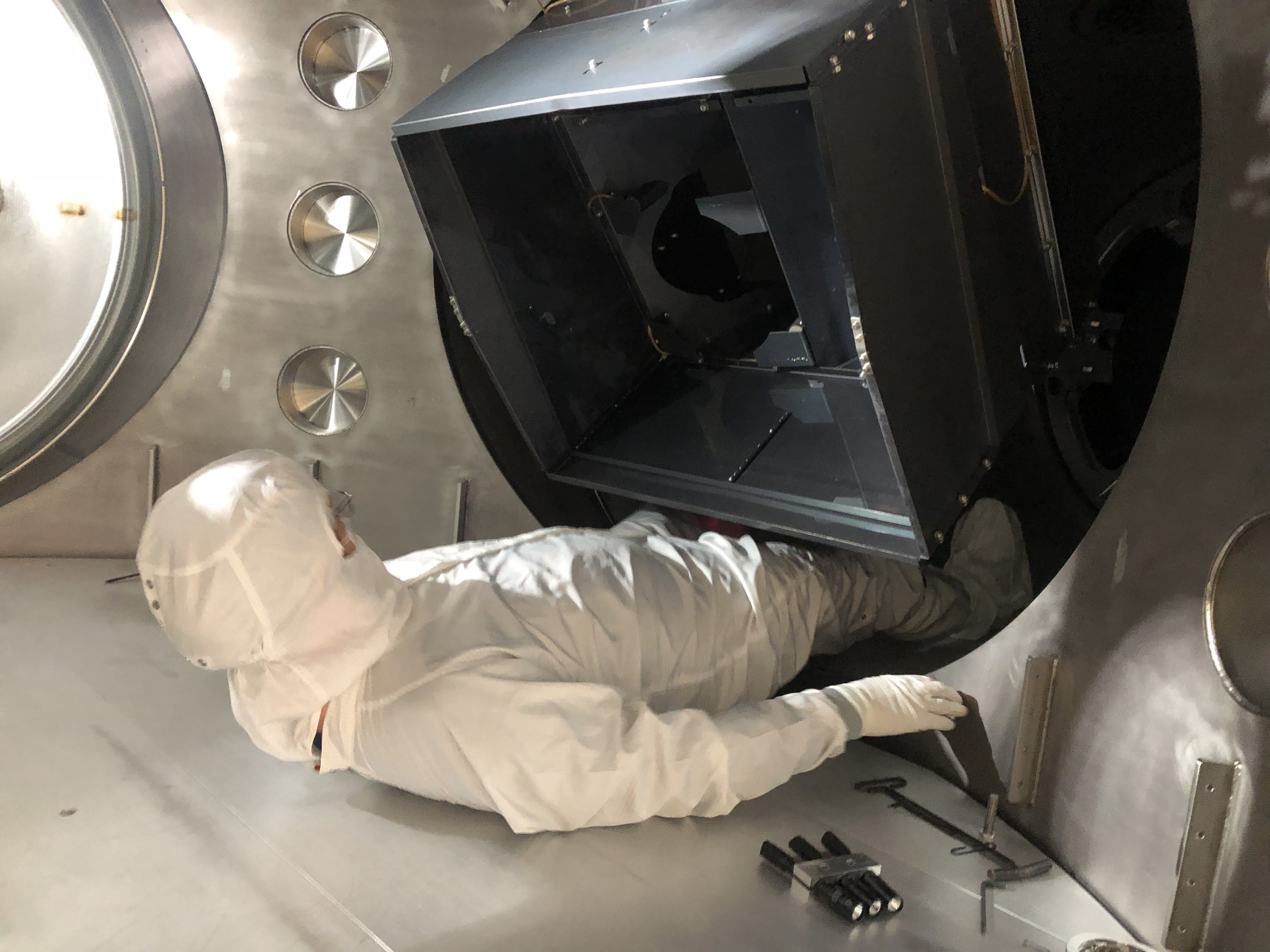
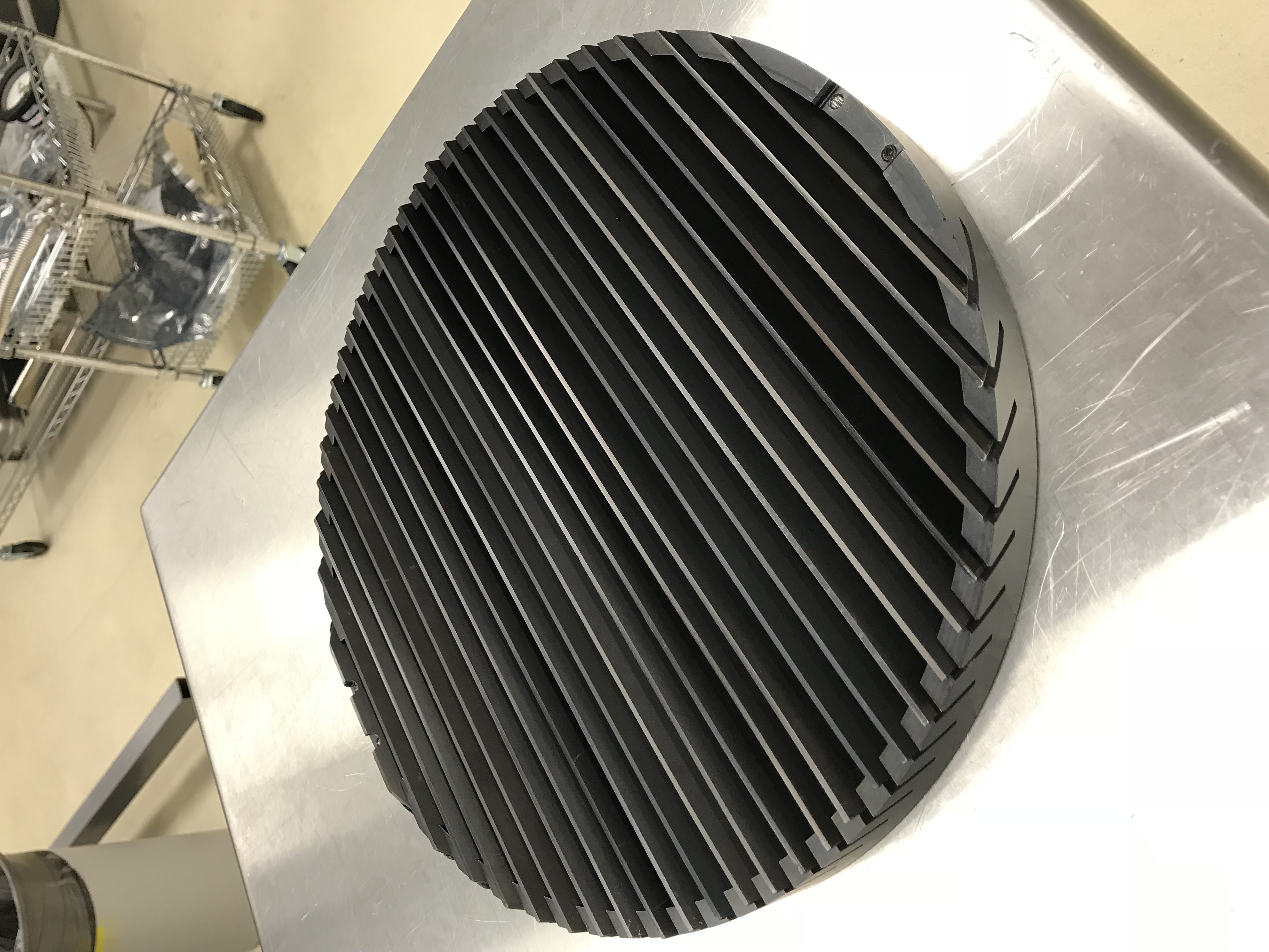
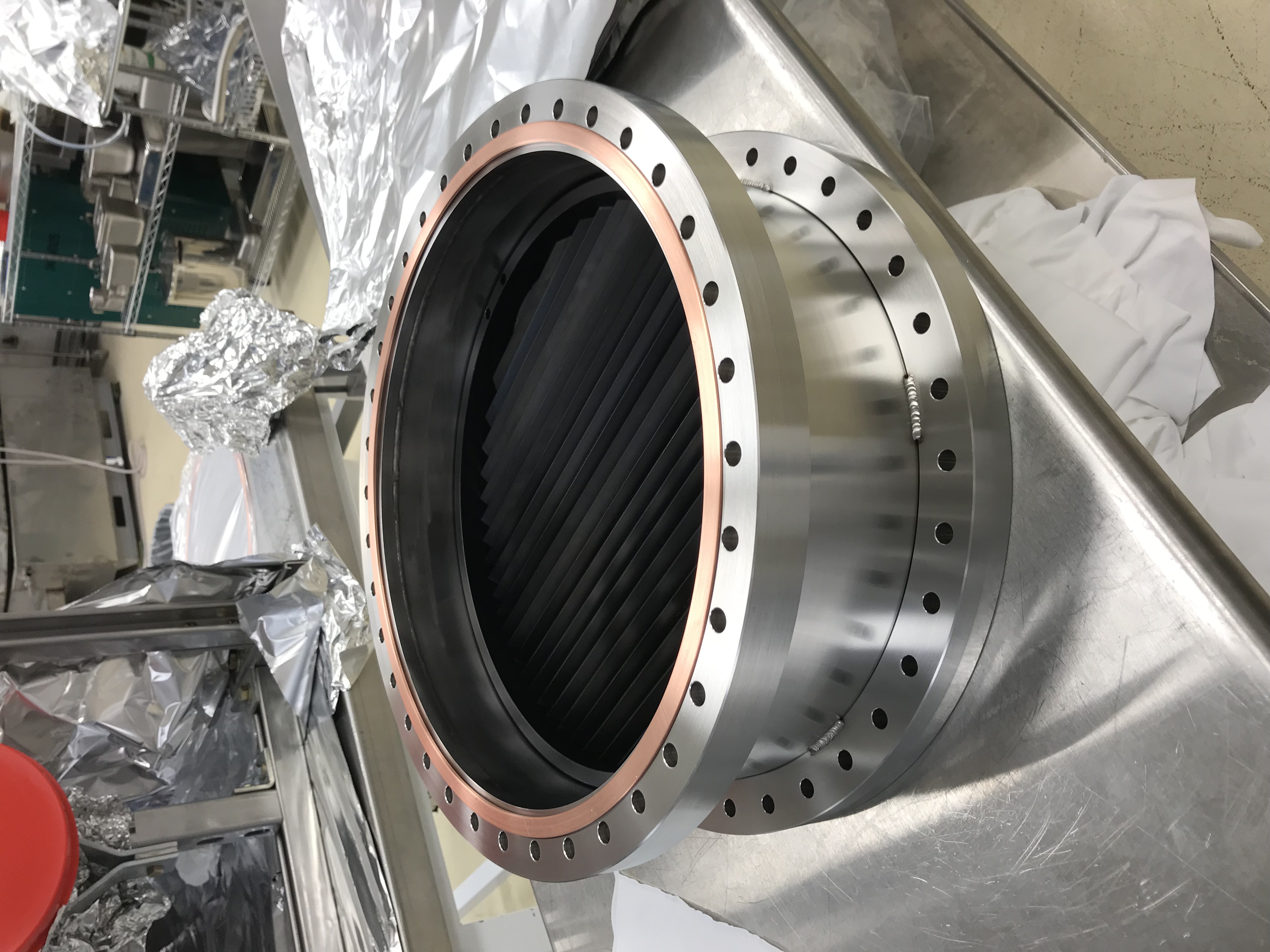
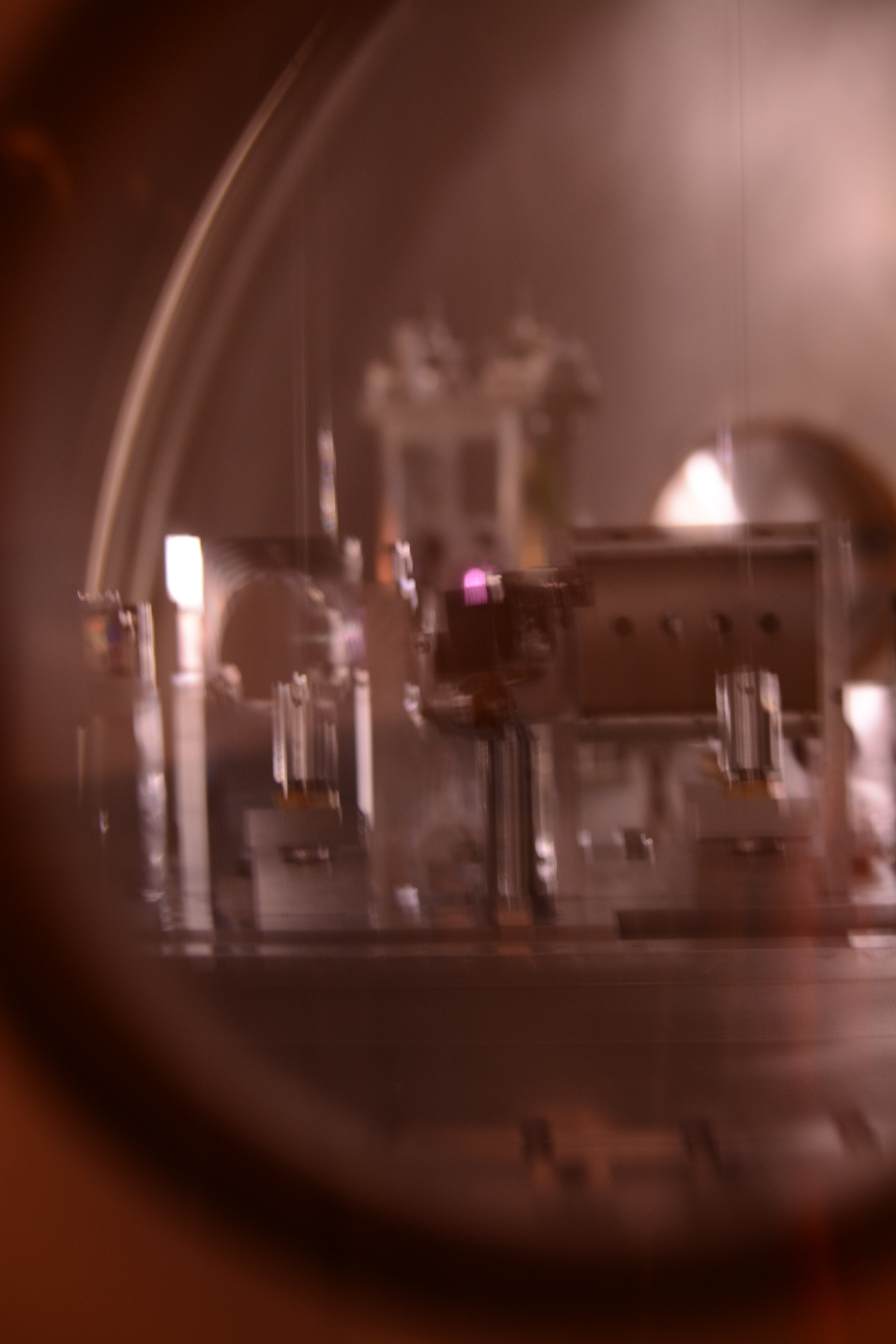
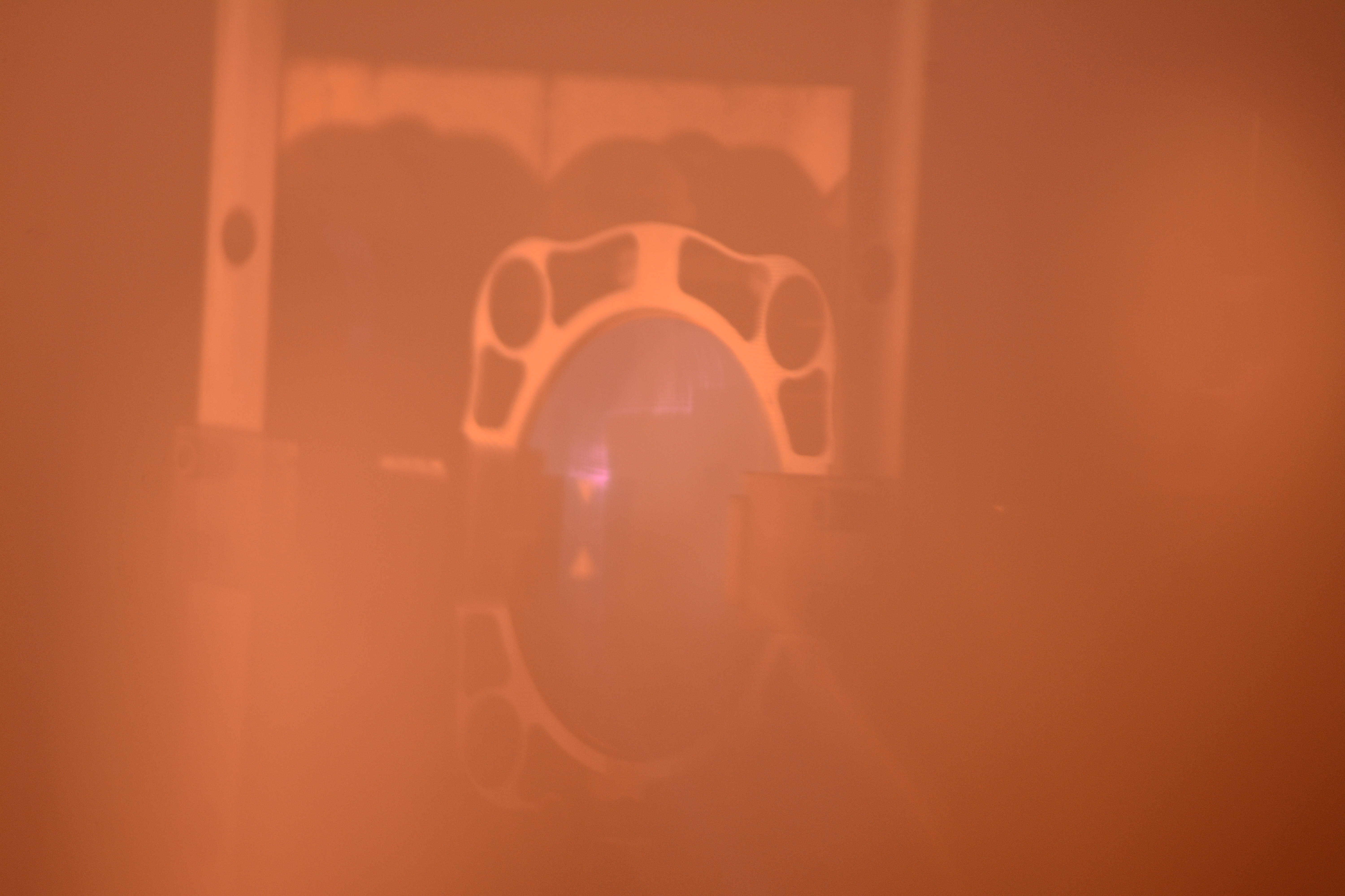
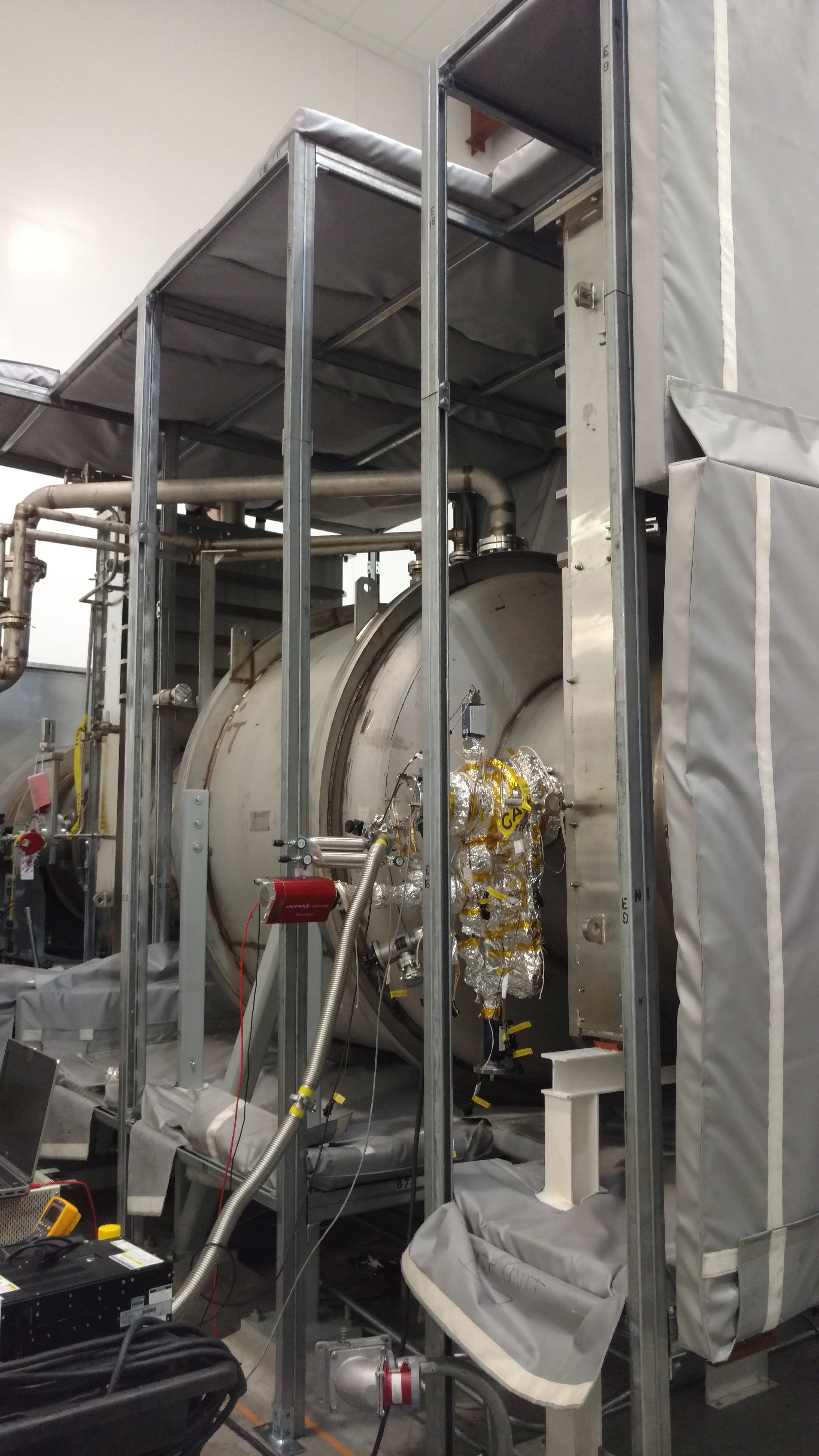
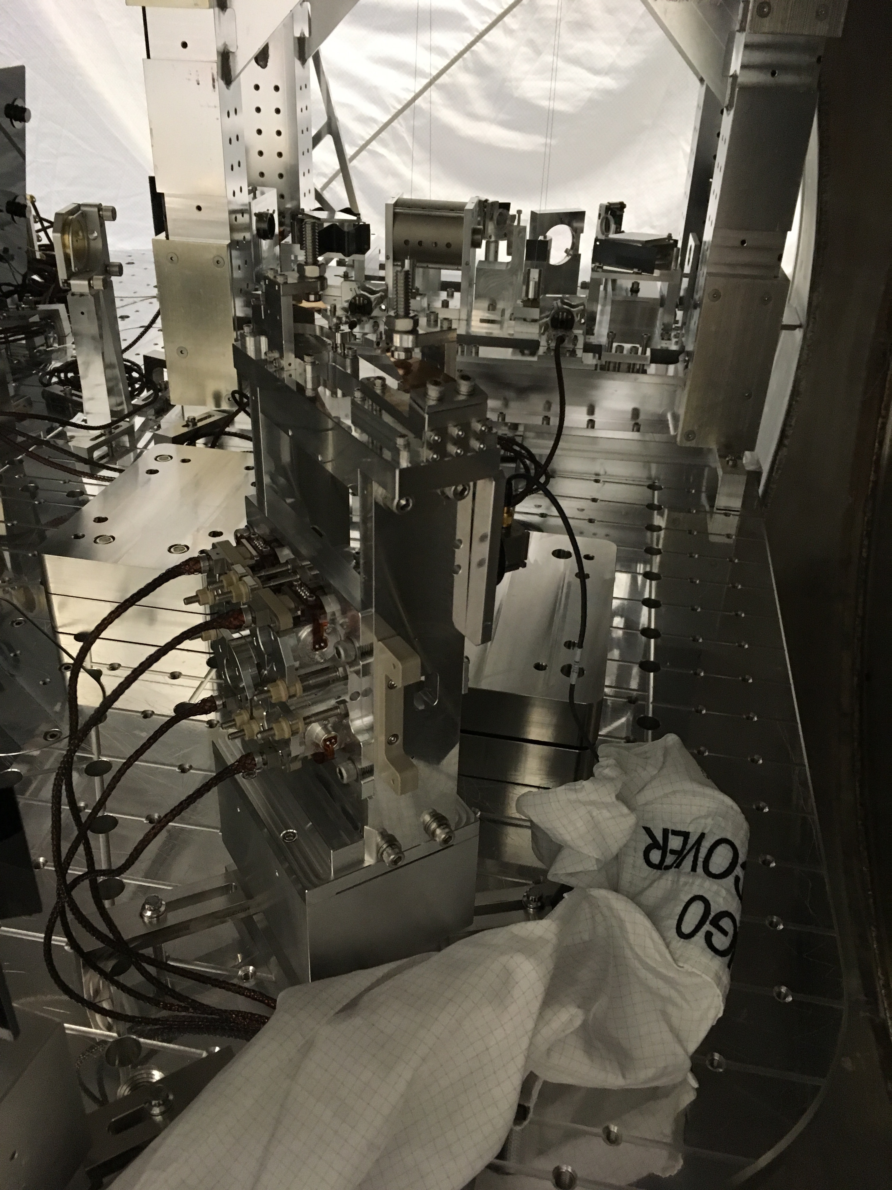
This morning Corey, Niko and I went to EX and installed most of the remaining PCAL baffle pieces. We looked over the panels, top-gunned them, then I went inside and Corey and Niko handed the pieces to me from the door. After putting the pieces on, I tried to get a couple of picture of the install and any particulate. First attached image is a view of the installed panels from approximately the the aperture of the arm cavity baffle.
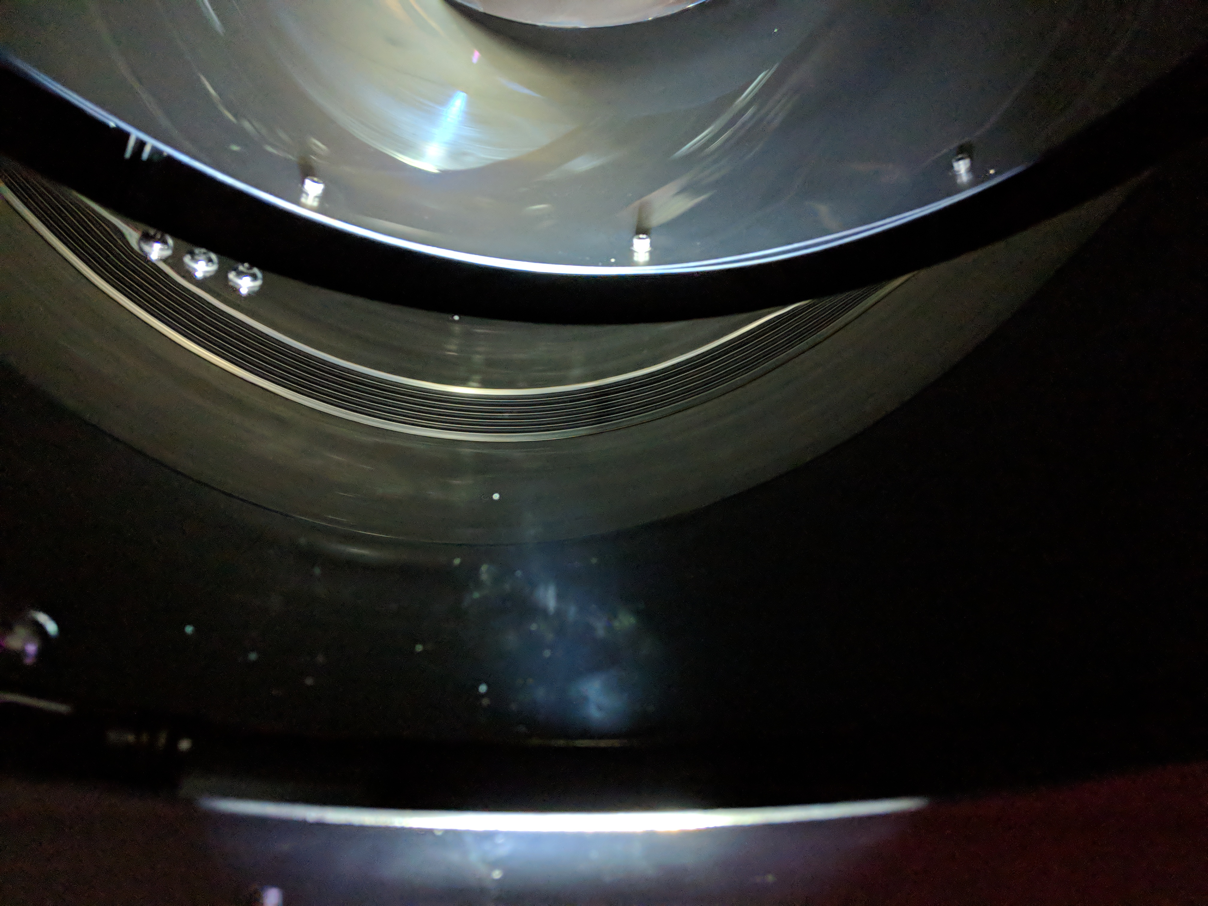
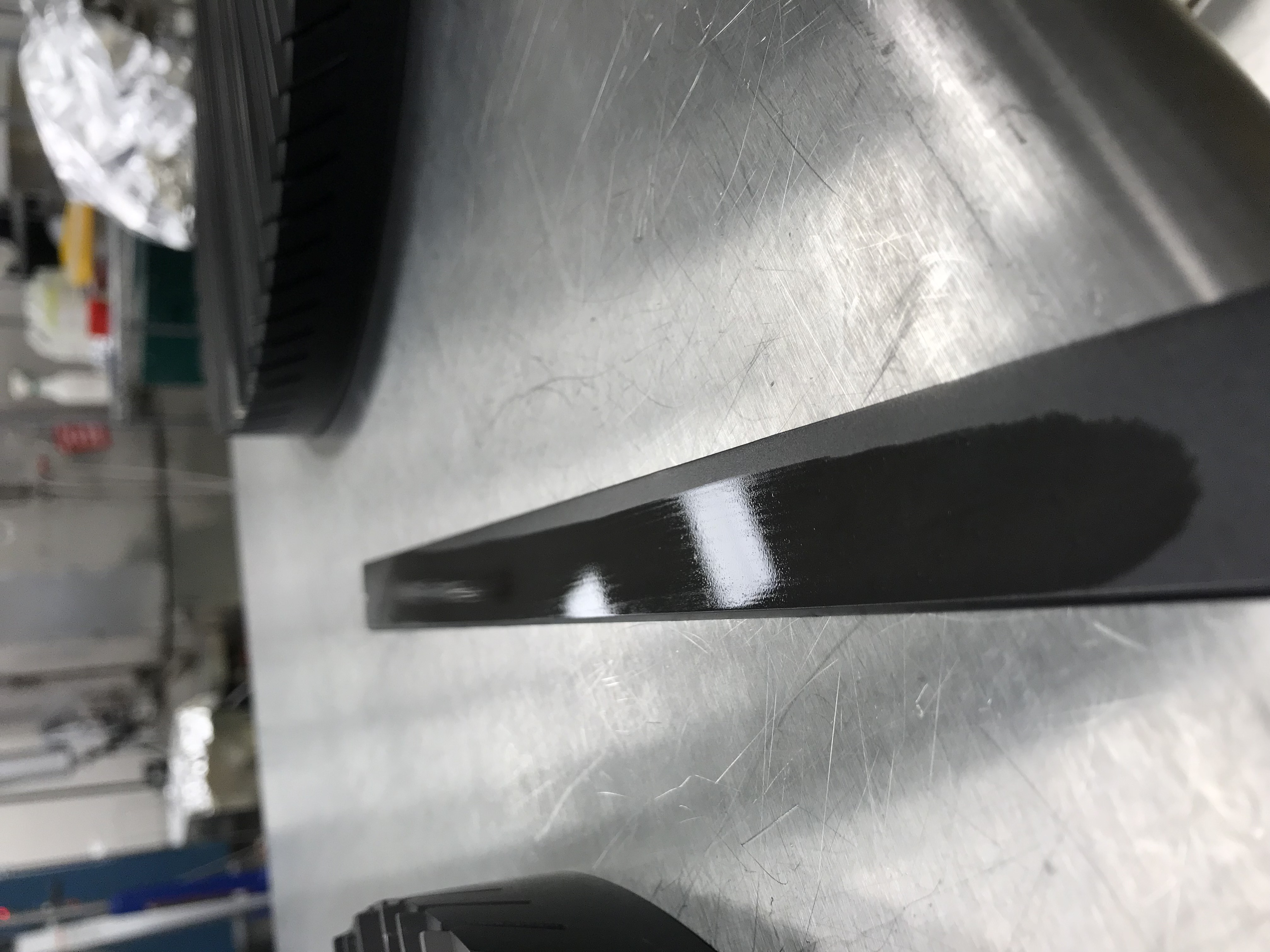
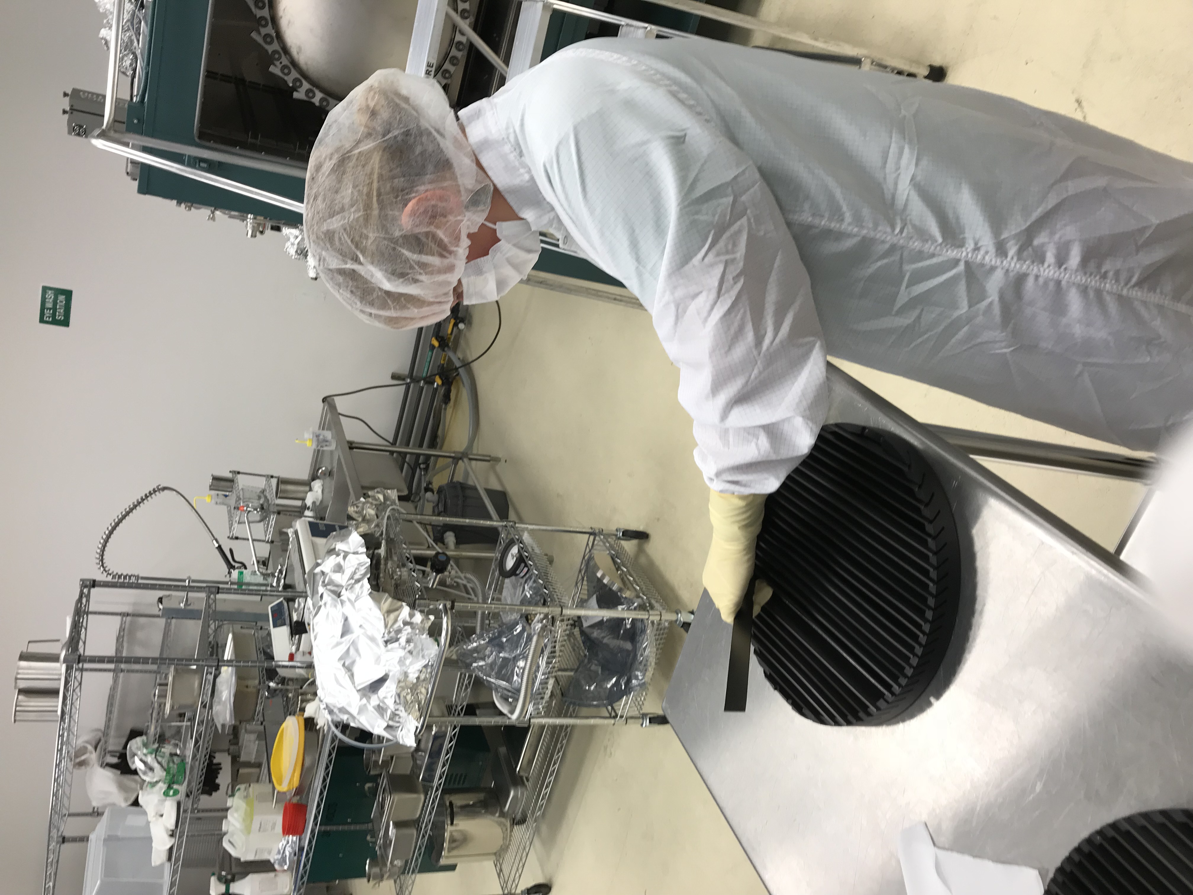
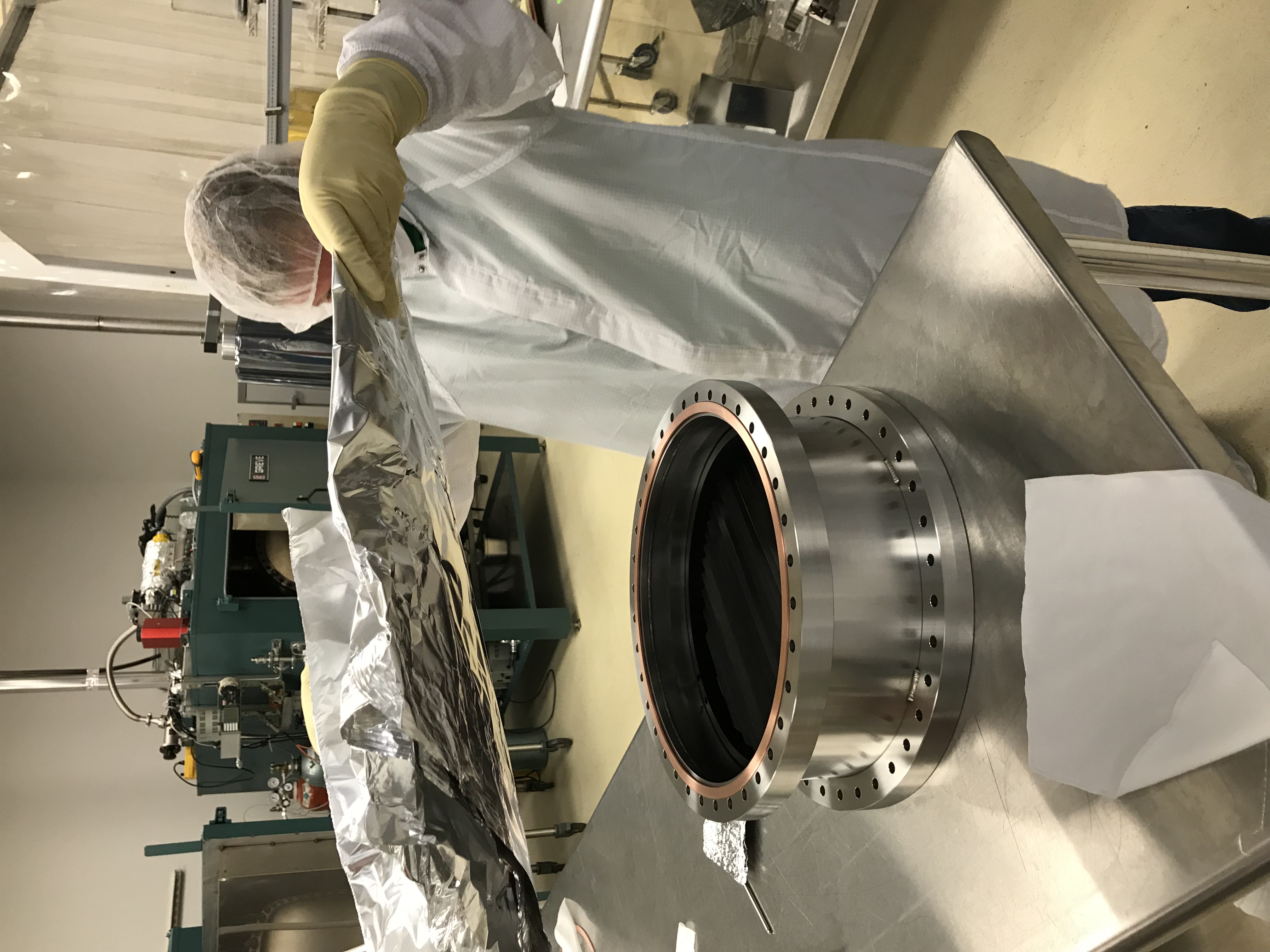
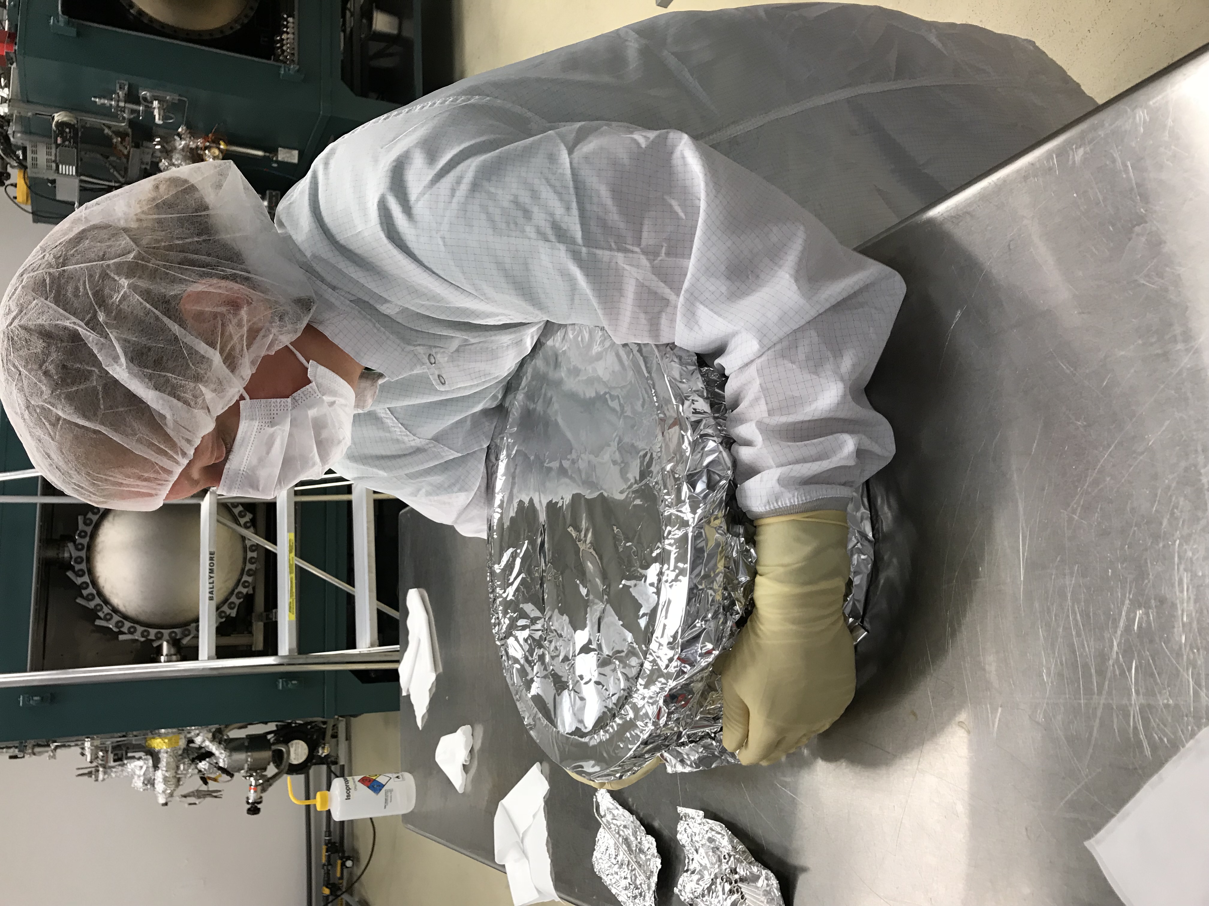
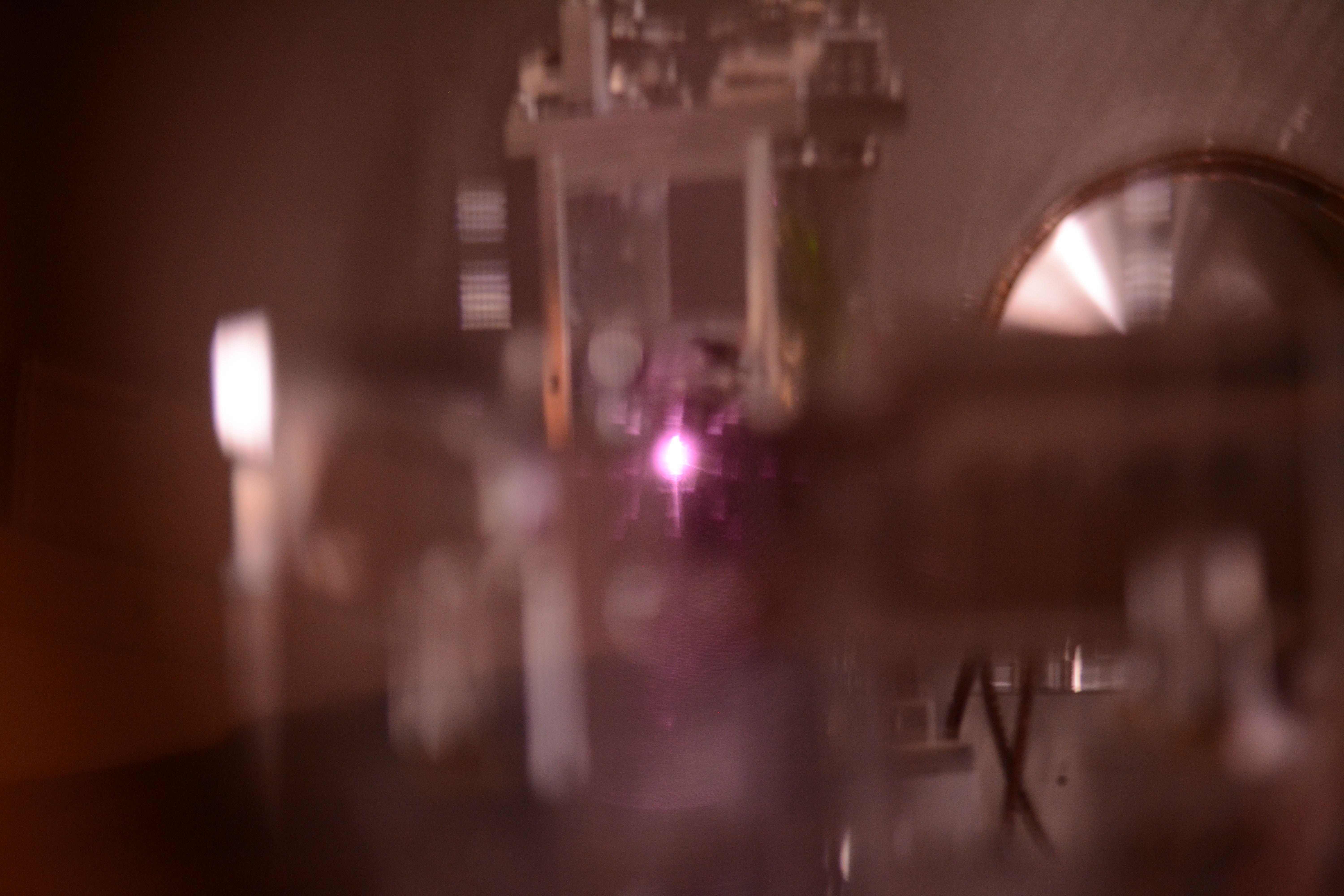
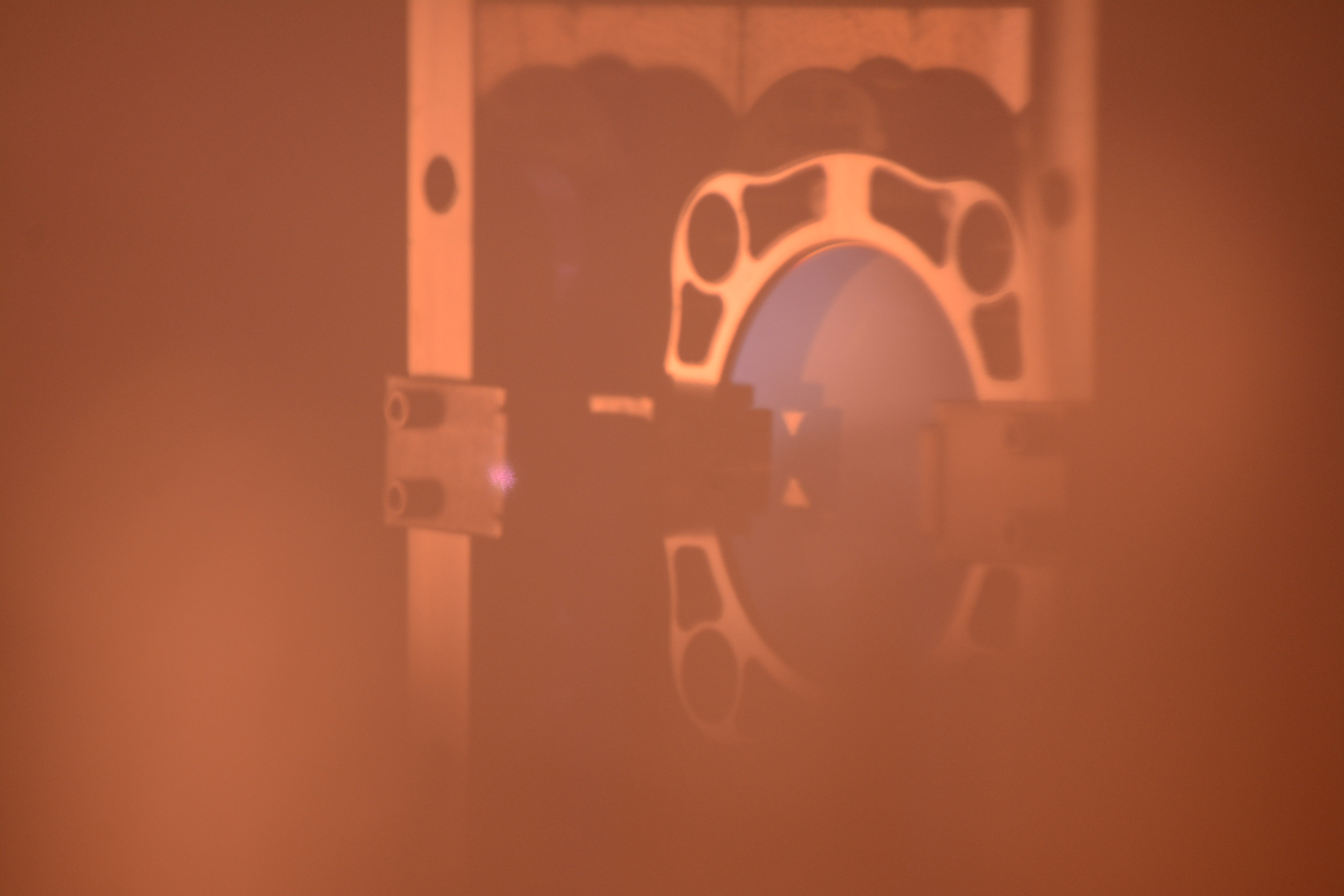
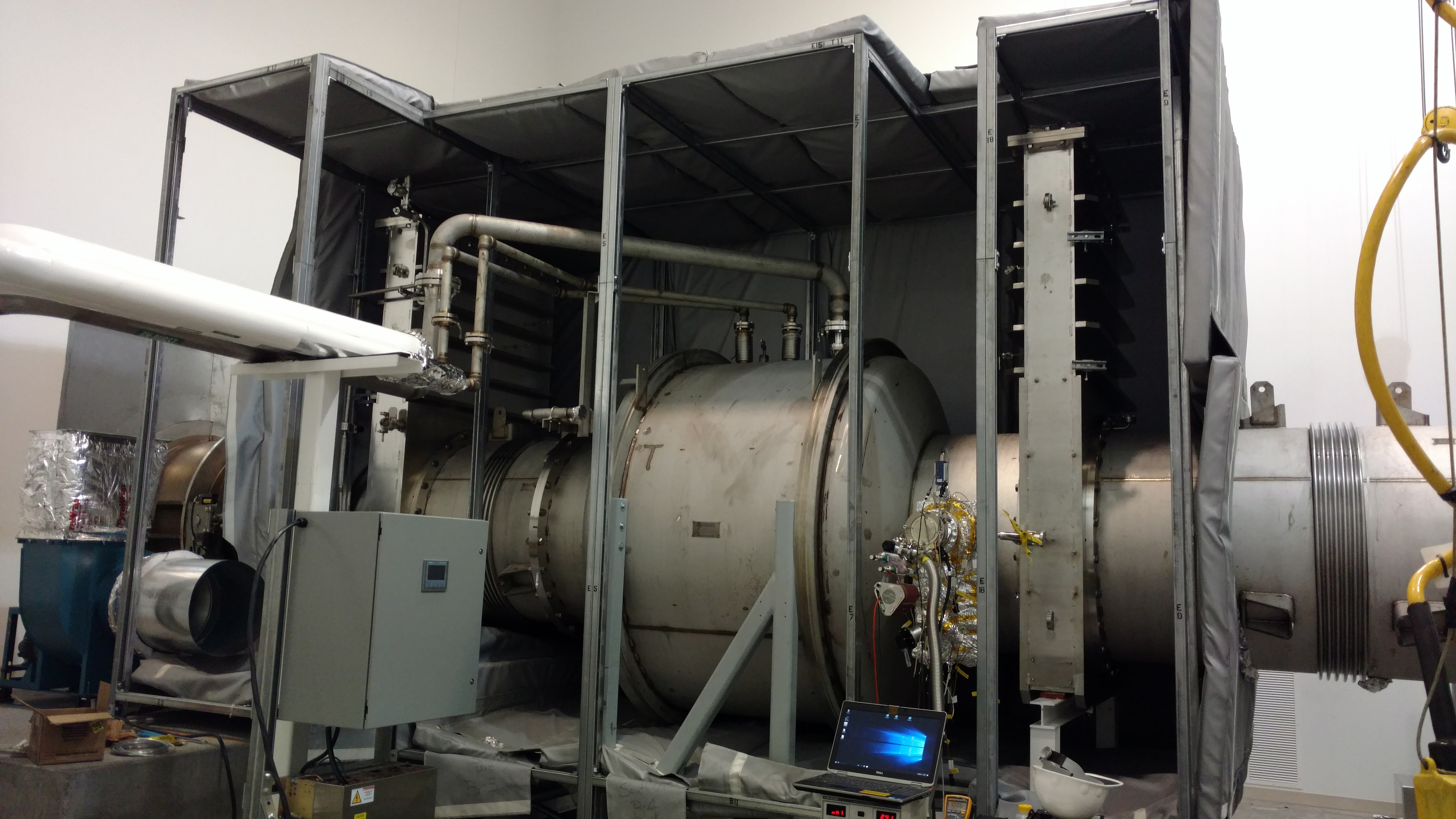
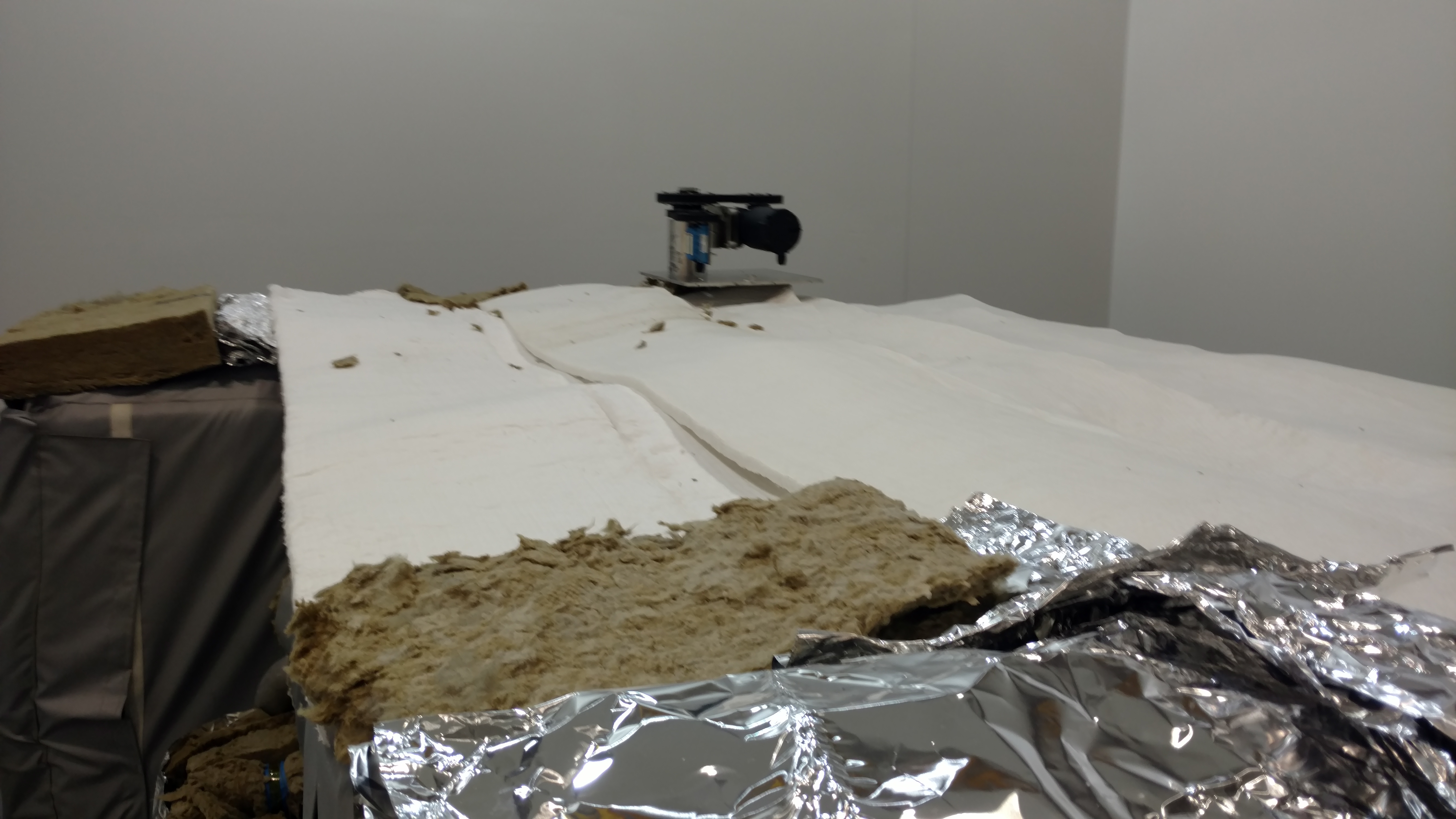
The barrel baffle pieces were installed a couple weeks ago, and the lower panel has been accumulating particulate, second image. I was pretty easily able to wipe away the fuzzies with a dry wipe, but the barrel panel immediately started accumulating again (third image is the lower panel piece after wiping). Before I left, I did not notice any increased particulate on the front baffle pieces we installed today. Travis noted before we closed ETMY (the first time?) that the panels on that PCAL had also accumulated some particulate, so it seems we will have to consider adding a wipe down step for the baffles to chamber close out.
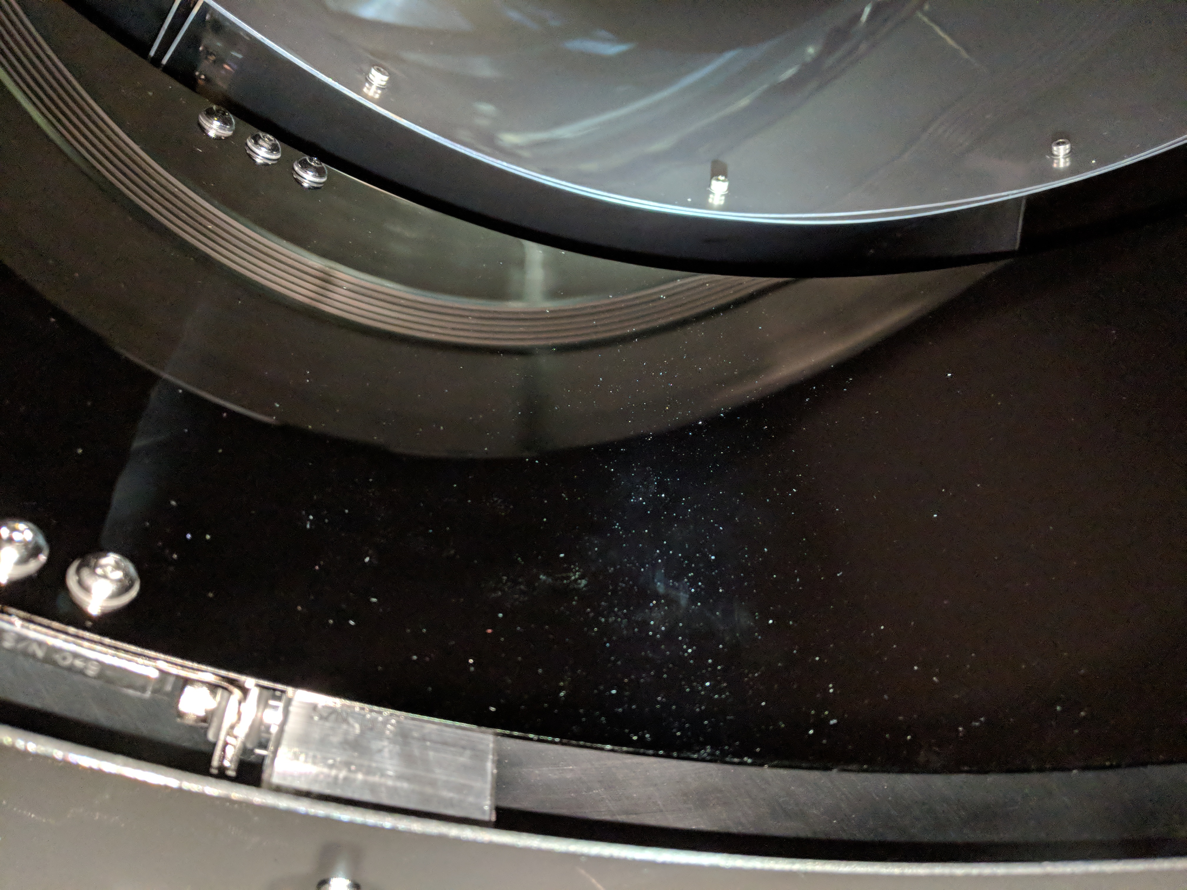
Black nickel barrel baffle panels + dry wiping is likely to contribute static charging, which may accelerate the rate at which particulate makes its way onto these panels - we should revisit this in discussion with SYS, perhaps via the "Updated procedures for handling the coated baffles" email thread.
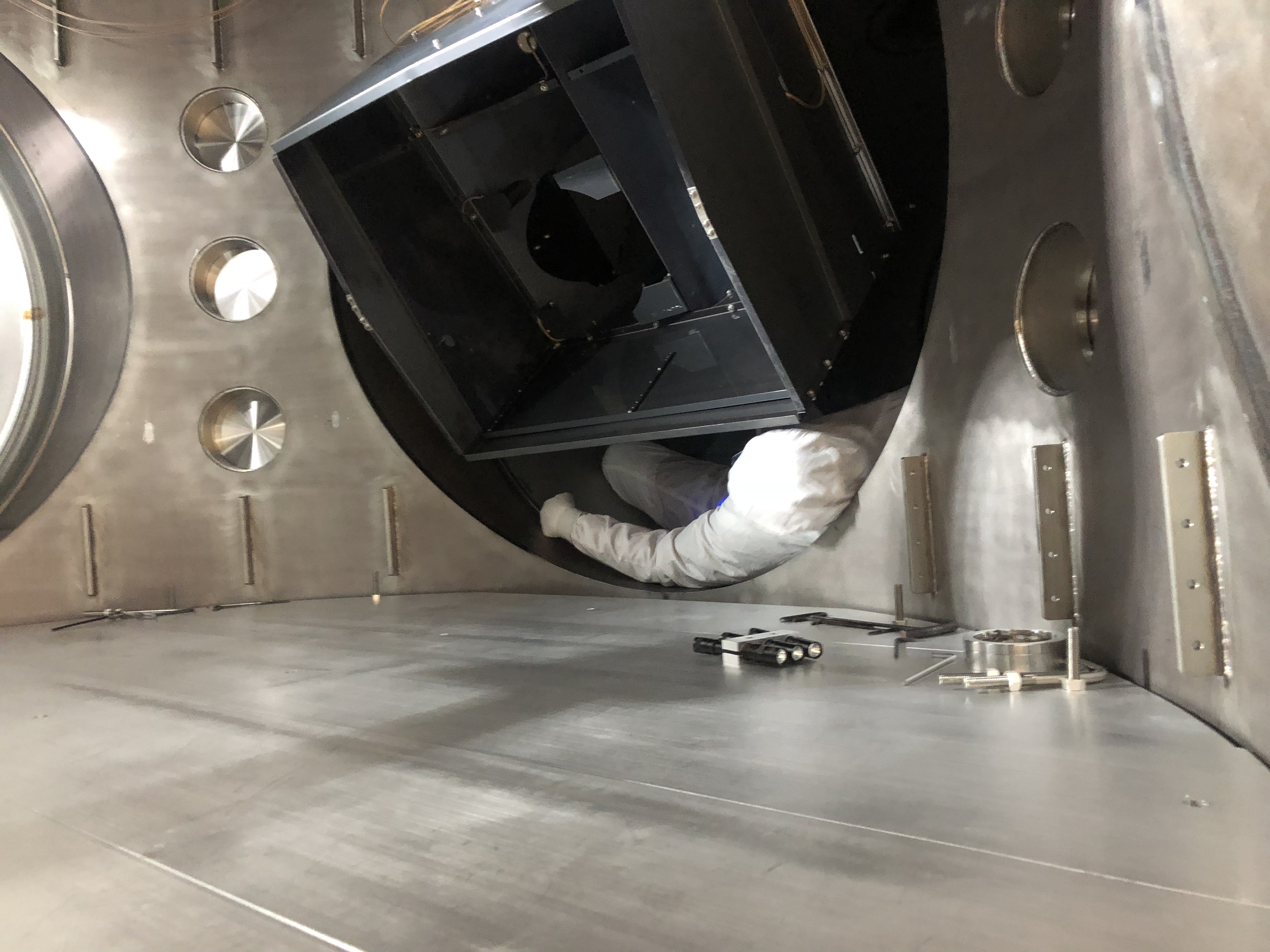
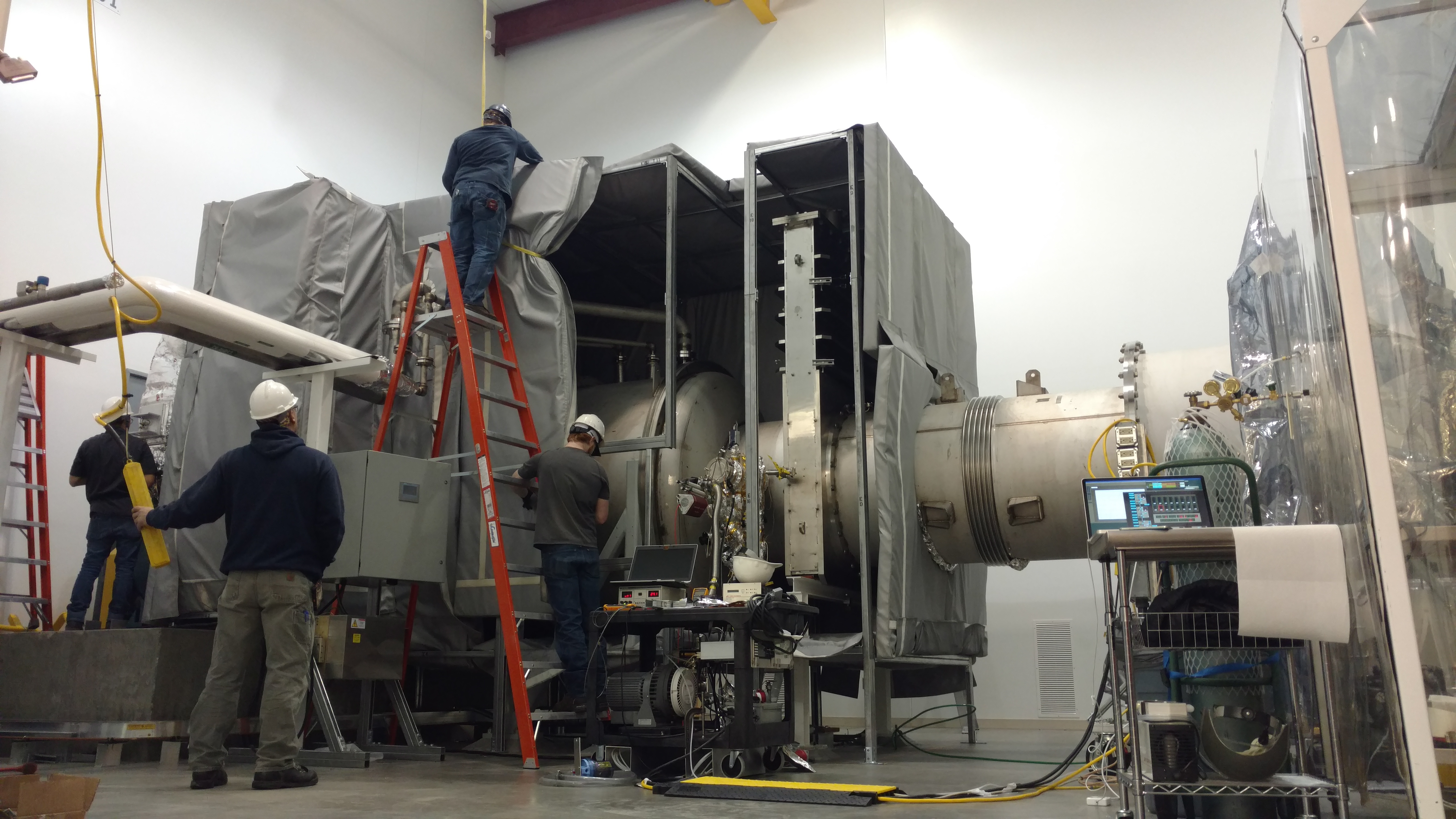
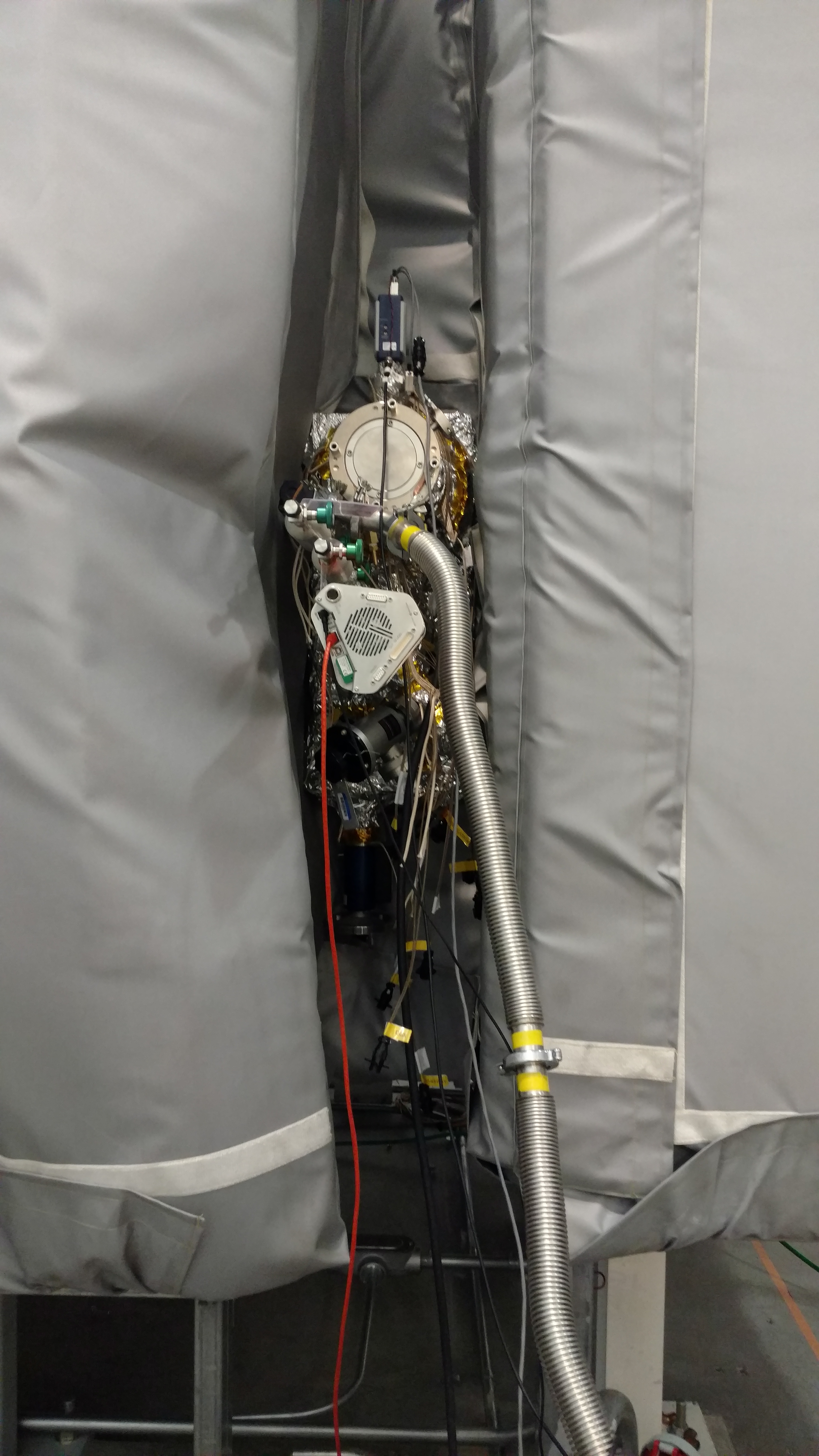
Jim doing the limbo under the EX Arm Cavity Baffle (ACB).
These pictures show that the PCAL "camera mirrors" were removed by this stage. I believe they were pulled after first alignment check, when we started removing screw in preparation for bracket install.

