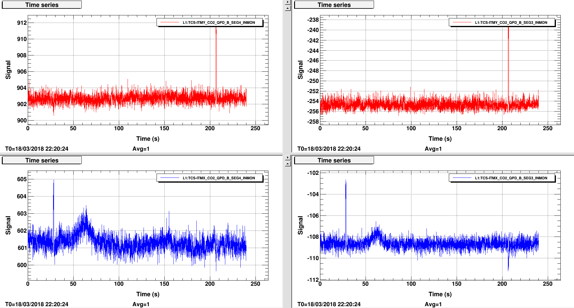
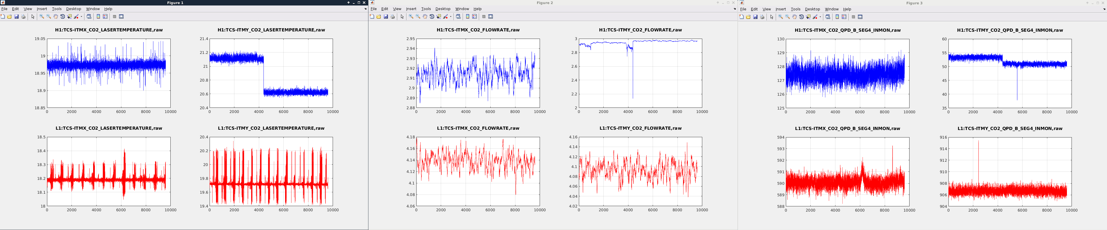
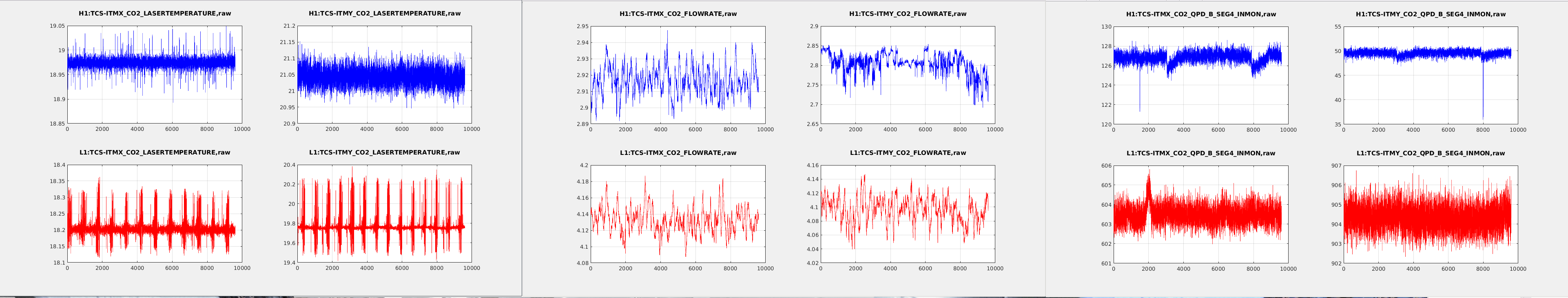
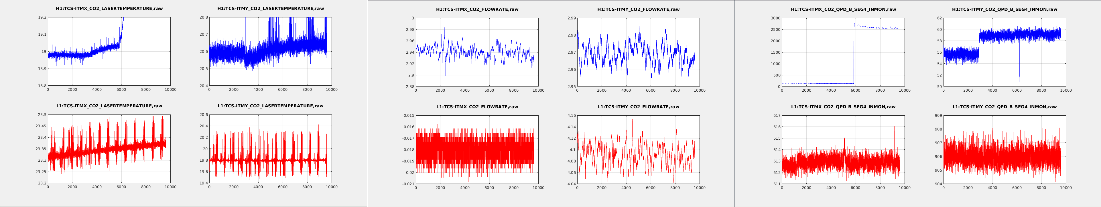
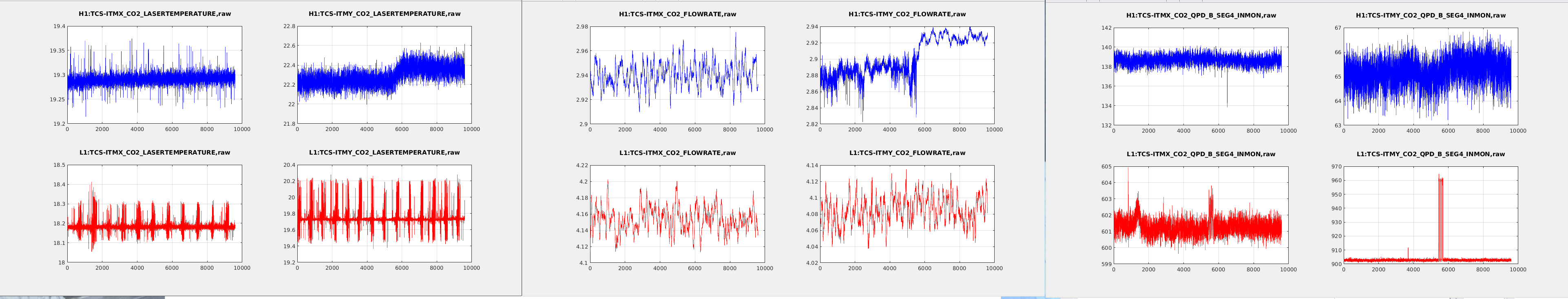
I've expanded my TCSY glitch investigation to include L1 TCS signals. The attached plots recreate my H1 plots in alog 41039, and now include the corresponding L1 TCS signals. Most noteable in the L1 TCS LASERTEMPERATURE signals is a noise pattern on top of the DC temperature signal, and in H1 TCSX has regular noise glitches, both directions, and TCSY appears to have the same glitches, just constantly. The FLOWRATE signals in H1 and L1 are very similar. The QPD B SEG4 INMON signals in H1 show instantaneous level changes, and some downward spikes, and the L1 signals show some upward spikes, but no level changes. All plots show raw data, each is about 10 minutes in duration, H1 signals in blue, L1 signals in red.
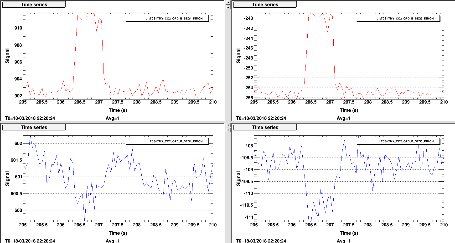
TCSX and TCSY QPD segments are glitching every 15 minutes. The absolute drop in the signal during the glitch varies between 6 and 15 counts, and the shape on the segments and on TCSX and TCSY are the almost identical. These glitches are also happening in L1 TCSX and TCSY QPDs. Plot attached shows a TCSX glitch on the left and TCSY glitch on the right.
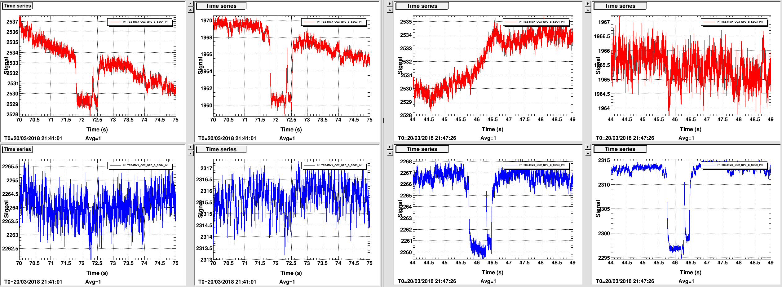
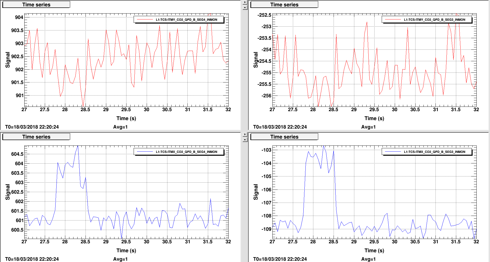
L1 TCS QPD glitches: up instead of down, and in one QPD more than another, but overall shape is very similar to glitches in H1 TCS.