betsy.weaver@LIGO.ORG - posted 13:47, Tuesday 13 March 2018 - last comment - 10:32, Thursday 15 March 2018(40995)
ETMY BSC10 door closed
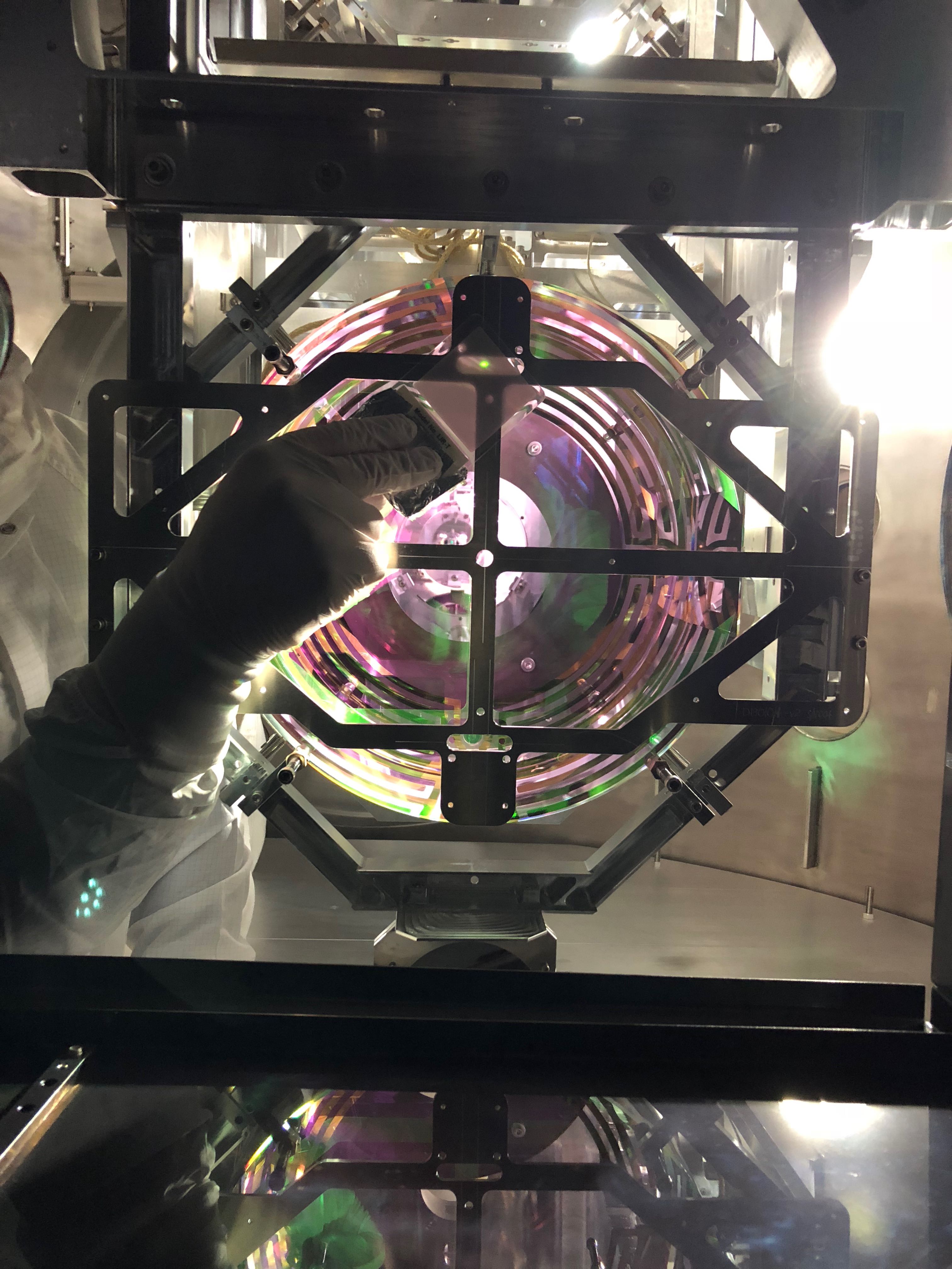
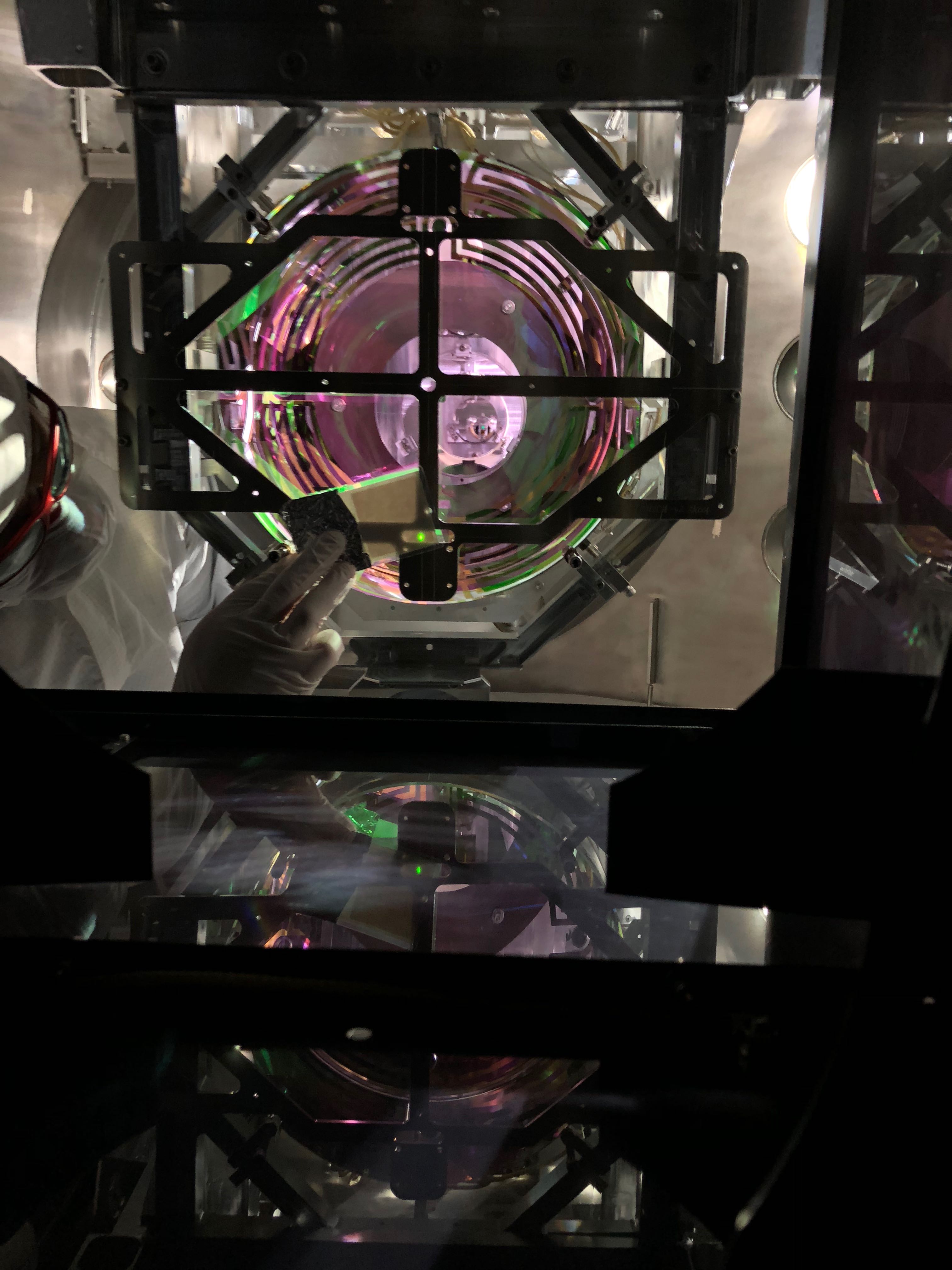
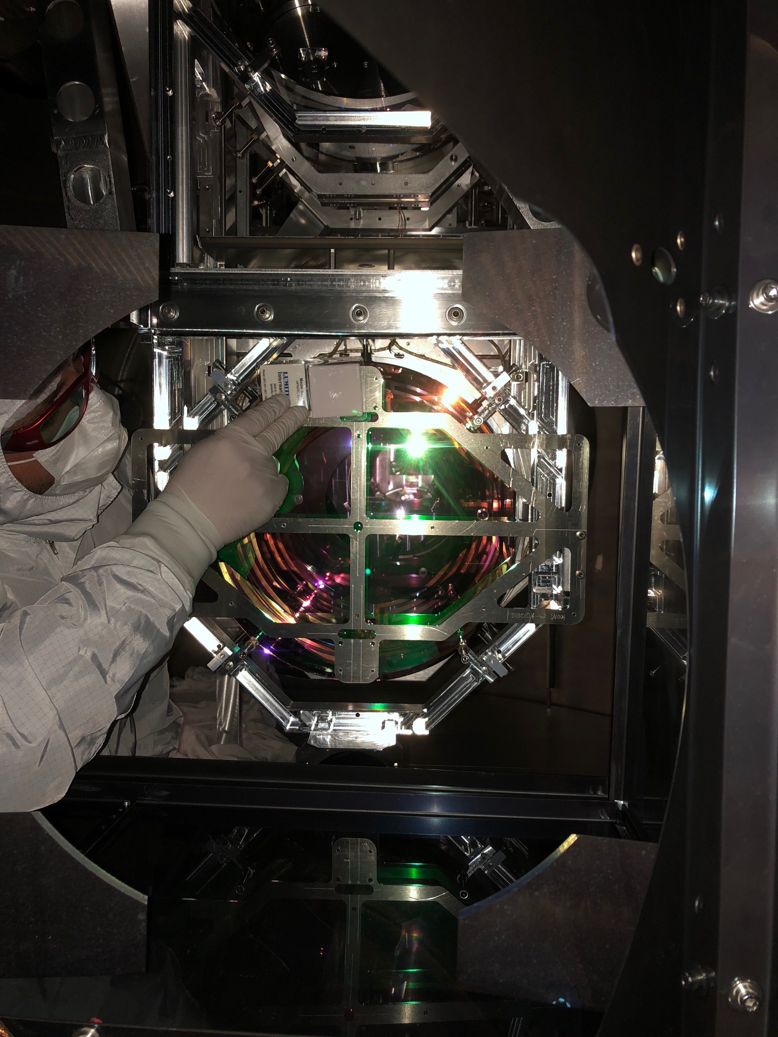
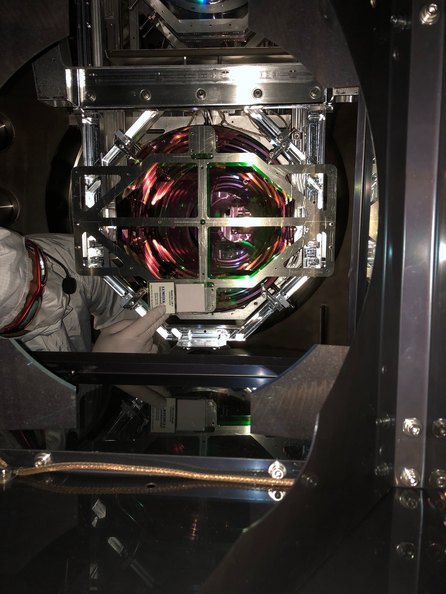
Today, I went in and pulled the 2nd First Contact sheet after the reapplication yesterday afternoon. Unfortunately, the 2 small glint blemishes that I didn't like yesterday were still there. So, they are either in the coating, scratches, or are not coming off. So, I then completed the closeout steps of:
1) N2 blow, measuring charge (details below)
2) Placing the 1" witness optic on the side of the QUAD structure
3) Jim unlocking ISI
4) Placing 3" horizontal wafer below ETMY QUAD on floor
5) Mounting 3" vertical wafer on lower front of QUAD structure
6) Wiping the floor on the way out
7) Removing tools
8) Kissel running TFs - 3 per suspended chain - all good
9) Launching door crew
Door on by lunch, started work at ~9:30am.


Details of the N2 deionization during this closeout:
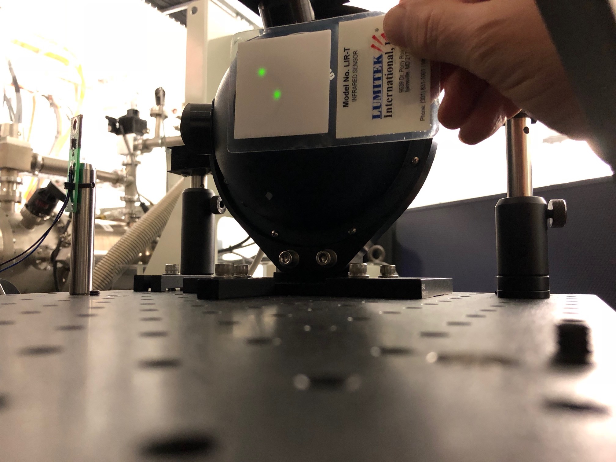
Measuring at the back of the AERM surface, the measured voltage started at ~8v, measured in the Center, UL, LR positions. We then pulled the FC and blew everywhere around the ETM and AERM for many minutes. Measuring again, the charge at these locations was down to ~2.5v. Another round of blowing, with a check of the zero of the meter in between, and the charge then read 1.3v in the Center and UL and 2.1v at the LR position.
5 minutes later we remeasured and found the charge at 0.4 in the center and -0.6v at UL.