This morning I completed the weekly PSL FAMIS tasks.
HPO Pump Diode Operating Current Adjust (FAMIS 8446)
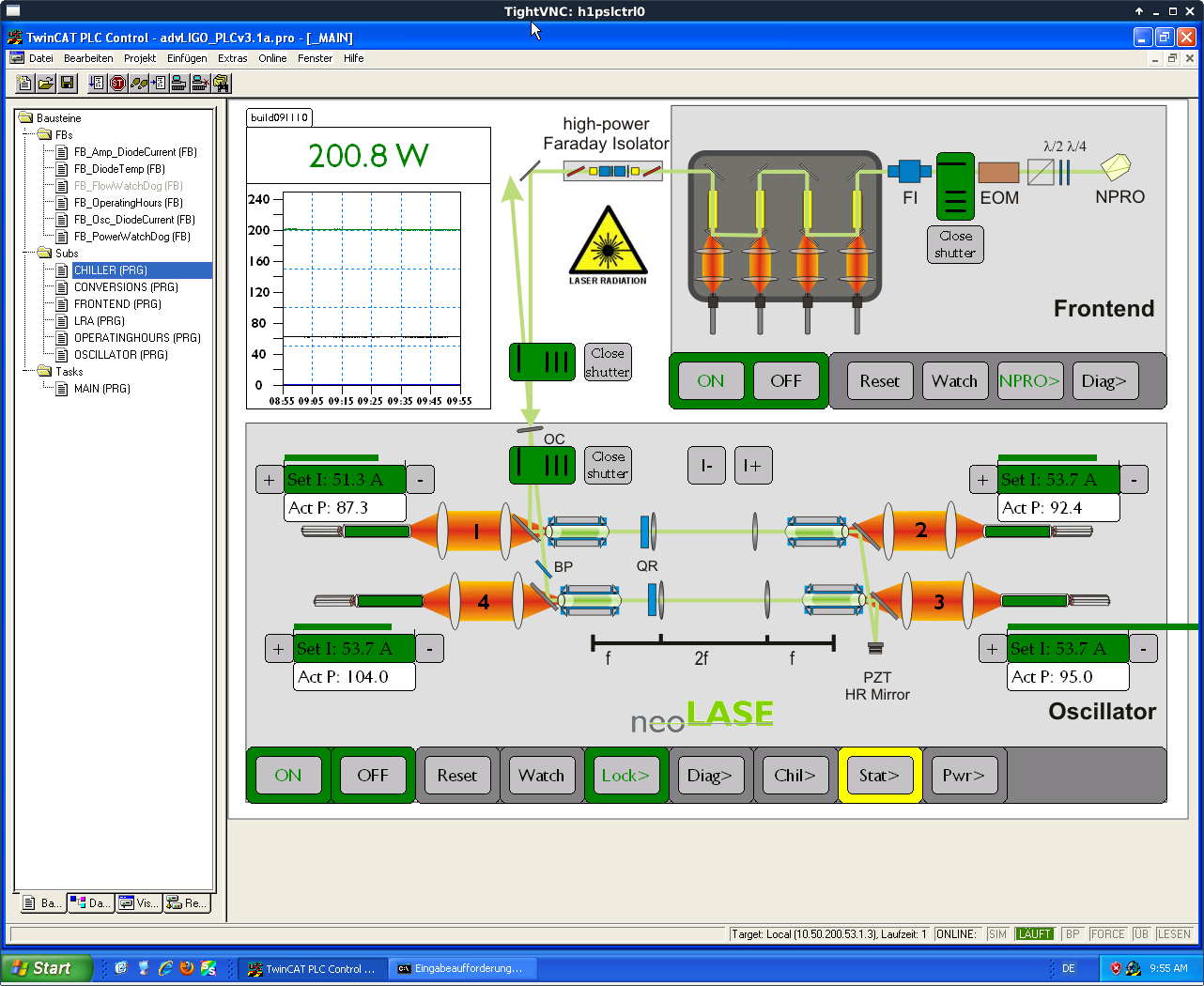
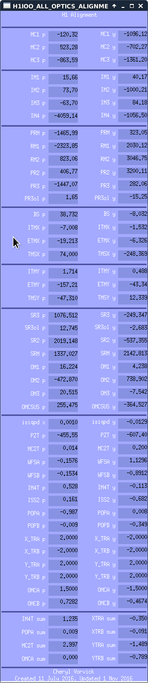
With the ISS OFF, I adjusted the operating current of the HPO DBs, changes summarized in the below table. A screenshot of the PSL Beckhoff main screen is attached for future reference, as usual.
| Operating Current (A) | ||
| Old | New | |
| DB1 | 51.1 | 51.3 |
| DB2 | 53.5 | 53.7 |
| DB3 | 53.5 | 53.7 |
| DB4 | 53.5 | 53.7 |
DB operating temperatures remain unchanged. The HPO is now outputting 155.1 W, and the ISS is back ON. This completes FAMIS 8446.
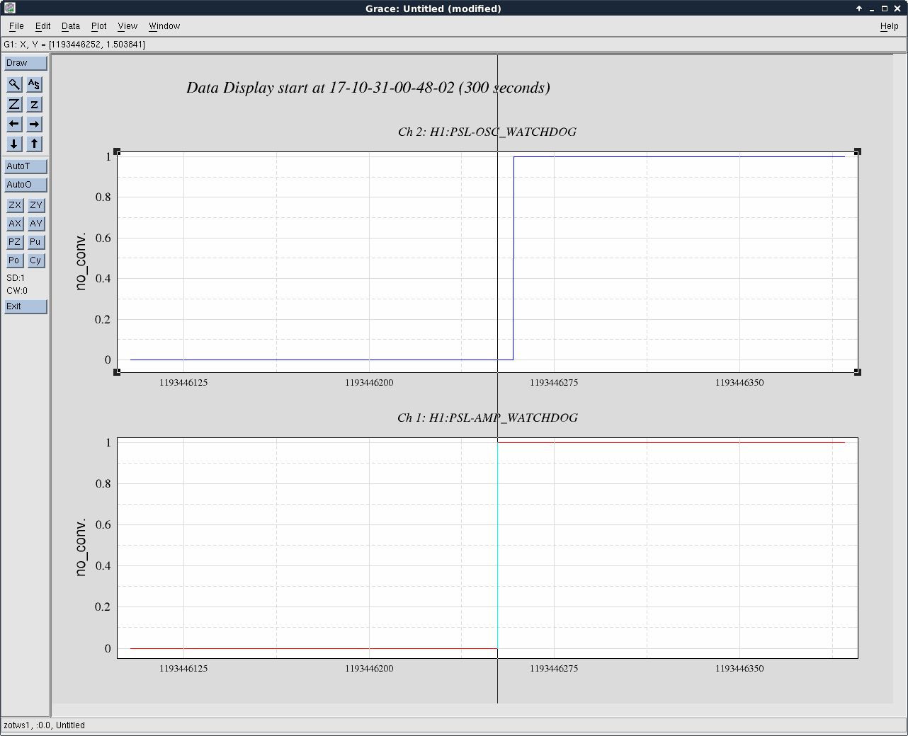
PSL Power Watchdog Reset (FAMIS 3674)
I reset both PSL power watchdogs at 16:49 UTC (9:49 PDT). This completes FAMIS 3674.
Yesterday, Travis found the mechanical rubbing point on the ITMY - we ran a few short TFs and things look much more suspended. The beam still is on the oplev, I made some small bias adjustments to center it up, but we should be ready for a full suite of TFs as only cleaning is left to do on this unit, which won't happen until closer to closeout.
Note, my new slider values for centering on the OPLEV are
P = -67
Y = -183
Recall, these values are still in the ballpark of the IFO aligned values which we haven;t touch much except to repoint for reference due to the venting of the chambers.
This sus has been hanging damped and aligned overnioght in air and should stay this way until notified otherwise (cleaning, ISI rebalancing in a few weeks).
TITLE: 10/31 Day Shift: 15:00-23:00 UTC (08:00-16:00 PST), all times posted in UTC
STATE of H1: Planned Engineering
OUTGOING OPERATOR: None
CURRENT ENVIRONMENT:
Wind: 9mph Gusts, 7mph 5min avg
Primary useism: 0.02 μm/s
Secondary useism: 0.15 μm/s
QUICK SUMMARY:
Corey taking over so I can do IO work:
15:15 Chris into LVEA
15:18 Norco with LN2 to EX (80)
15:49 Hugh to HAM6 to work on cable dressing
15:54 Chris out
16:04 Betsy out to the floor for parts
16:20 Krishna and Jim out to EX
16:30 Chris to both end VEAs
16:46 Betsy to ITMX
17:00 Gerardo into optics lab
Richard came into my office this morning to tell me that the laser was off. Pulled up the laser status screen to find that power watchdog was activated ~12 hours 20 minutes ago (~6 pm Monday). The laser was brought back.
As Peter says, the laser tripped due to a trip of the power watchdog. Looking at the relevant channels at the time of the trip, the 35W FE watchdog tripped first, with the HPO watchdog following ~6 seconds later due to the loss of the FE (see attachment). Beyond that, I can't find any reason for the FE power watchdog to have tripped. All channels for the FE and NPRO appear to be behaving normally up to the trip, then everything cuts off (as it should with a power WD trip). Unclear at this time why the FE watchdog tripped. Maybe another occurance occurrence of the mysterious NPRO shut down that we can't explain but seem to see a few times a year?
Edit for spelling at 10:30 PDT.
Filed FRS 9337 for this trip.
We usually blame NPRO shut-downs on the UPS the NPRO is plugged into. Maybe that's what happened here again?
J. Kissel I've B&K hammered the response of a bunch of other stand-alone components in HAM2: New MC13 Table Baffle, PSL DownPeriscope, MCREFL Periscopes, and New ISI Table Baffles. The prognosis is not good. Every component aside from the PSL down-periscope has resonant features below, if-not-well-below 150 Hz -- the original requirement from the SEI team to keep ISI 30 Hz UGF control loop design possible. Granted, the MC REFL Periscopes haven't really changed, but this data shows that (a) they are different from each other, and (b) that Periscope 2 is confirmed rattly mess. I can only hope that we can some how stiffen & and damp, instead of just shoving viton everywhere. I fear it's far too late in the schedule... This being said, I must give props to the SLiC design team for ramming through an incredibly quick design-to-installed turn-around, and I appreciate that not everything could have been thought. We know from LLO that all this new baffling is doing the right thing as far as scattering goes. See the .pdf for transfer functions. I'll note that *everything* I hammered in HAM2 (including PRM and PR3 from LHO aLOG 39212) shows these resonant features at ~10.6 and 12.4 Hz. However, the ISI table baffles (a.k.a. beard baffles) seem to show this feature more prominently, and their mounting looks ... less-than-stiff ... so my guess is that since the accelerometer is mounted to the table in these measurements, they're coupling to every measurement. BUT, this is just a guess. I have a tough time believing that there's enough moving mass in those baffles to resonate as low as 10-12 Hz. Aside from this common feature, I list the remaining prominent low-frequency features here in tabular form for future reference: DOF IFO Y IFO X MC1/3 Table Baffles [21.5 29.38 44.62] [29.62 36.88] PSL Down Periscope [238.4] [269.8] ISI HAM2 Table Baffle [12.38 40 60.75] MCREFL Periscope 1 [124.6 124.8 140.8 194.6] [22.00 42.25 141.2 167.9 195.1 ] MCREFL Periscope 2 [31.75 124.6 142.6 167.8 201.4 285.0] [22.38 31.25 48.12 143.5 167.6 201.6 223.6] Pictures are attached to guide discussion and aide any repeat measurements in the future.
- Ed, Keita, Cheryl
[Spelling Ed from DAY Ops Shift duties so he can join IO Team for HAM2 activities.]
Afternoon's Activities:
Kyle R., Chandra R. Previous attempts to test for a high voltage cable connector short circuit were to no avail as the ion pump controller wouldn't energize the cable without the cable connector being mated to the pump connector (SHV Safety Interlock). Today we defeated this safety interlock by disconnecting the HV connector from the pump and installing a mating-sex connector in place of the pump connector. By doing this, the mating-sex connector depresses a spring contact within the HV cable connector and "fools" the controller into thinking that the cable is connected to a grounded ion pump. Anywhoooo....this approach worked and the non-terminated HV cable would now energize. The result was confirmation that the short circuit is, in fact, internal to the pump-end HV cable connector as the controller's output was power limited, 700V @ 0.5 amps, while not connected to the ion pump. As such, we'll ask the EE/CDS folks to redo this pump end HV connector as they have a much better track record of doing this successfully than we do!
S Cooper, J Warner
I've been using a particle swarming script developed by Conor, to design some sensor correction filters in different environmental conditions., the method used by the script is described in G1700841.
I chose a starting point of GPS time 1193385618 (8AM 30th October 2017 UTC) and used data for 2 hours on ETMY. During this time the microsisem was around 0.2-0.3 um/s and the wind speed was around 10m/s. I configured the swarm to have 4000 particles, set the RMS counting from 2Hz down to 1mHz, set minimum and maximum Q's to be 0.05 and 5 respectively and set the gains to range from 0.95 and 1.05. The result of this swarming produced the filter shown in blue in the first plot and its complement in red, plotted against the sensor correction filters currently used (Filter Module 5 CML BB).
For these conditions, on this chamber the ending velocity RMS (how we're measuring how well the filter performs) is basically equal to the sensor correction filter currently used. Nevertheless Jim and I will try this filter out on ETMY and see whether this has any problems / benefitsover the old filter overnight on ETMY.
We've successfully quacked the filter to the Y IIRHP path on ETMY, set the end-station ST1 conf guardian to 250_Eq blend sc state (this uses the IIR path, I checked that this is the only st1 sc path on and all the other bits are on), turned the st2 sensor correction back on, turned the hepi Z sensor correction on and re-isolated the platform. I want to leave the ISI in this config overnight, for analysis. So far it seems stable.
II 1127 & WP 7195
Returned the model to nominal configuration to allow testing/troubleshooting of the rogue excitation problem associated with the C2 coil driver.
Filters are changed and after a couple weeks of circulating just up at the Pump Stations, the valving has been returned to allow flow through the LVEA piping. The Actuators are still isolated from the flow and I'll keep the system like this for at least a week or so to further bleed the piping and clean the fluid. Can't really do any testing until the HEPIs are unlocked so there is no rush to open up to the actuators.
J. Kissel I've taken new, more comprehensive B&K hammer response measurements of the H1SUSPRM and H1SUSPR3 cages, now that they have newly installed (what I'm calling) Venetian Baffles (see attached HAM2_NewBaffling_WithLabels.pdf for names of baffles) whose installation was finished last week LHO aLOG 39170. These baffles have pretty high-Q, low-frequency drum-head / longitudinal resonances (roughly aligned with ISI / IFO Y axis). PRM Upper: 42.38 & 46.75, 91.00 PRM Lower: 42.38 & 46.75, 75.62 PR3 Upper: 36.75, 75.6 PR3 Lower: 36.75, 83.12 My guess is that the lower frequency of the modes are the baffles bending in longitudinal in concert on the Venetian bracket, and the upper frequencies are their individual longitudinal modes. This mode-shape guess is based only on intuition, and that the lower frequency modes are seen in both upper and lower excitations. The cage's transverse modes appear to be relatively unaffected by the new baffles. I'm little surprised it hasn't stiffened up any of the transverse modes; oh well. These resonances have been identified by comparing against the history or cage resonance measurements for each of the SUS -- see the three pdfs: 2017-10-30_H1SUSPR3_CageResponse.pdf 2017-10-30_H1SUSPRM_CageResponse.pdf 2017-10-30_H1SUSPRMvsPR3_CageResonance_Comparison.pdf Note, also new with these measurements -- data out to 1.1 kHz. The former data is from LHO aLOG 6014 -- VA ON vs OFF data for H1SUSPRM and H1SUSPR3 LHO aLOG 8654 -- Former Cage Baffles on H1SUSPR3 Photos attached (and remaining HitLocations.pdf) are for historical reference for future repetition.
From Stephen and Norna
We (Stephen, Norna, Calum, Cormac) have done further experiments in the lab at Caltech to better understand the effect of the addition of the "Venetian blind" baffles ( D1700256 HSTS BAFFLE ASSY.PRM), on an HSTS and to help with the interpretation of the results seen at LHO.
A few caveats which should be noted:
a) We only have a bare structure - no vibration absorbers, hanging suspension, cables etc. attached. Also not as well dogged down as on site due to potential interference with baffle (our HSTS is not on a spacer). We have included baseline results displaying excitation of this structure without baffles mounted for comparison, see figures 2a and b described below.
b) We only used one baffle panel - so it was either attached at lower or upper position. See figure 1 for set-ups.
Basic findings
1) We show with and without damped baffle in upper position, exciting at top of structure in longitudinal (beam) direction and transverse. Basic conclusion, we do not see noticeable new resonances when exciting structure itself. See figures 2a and 2b
2) We only see extra low frequency ( ~ 40 Hz in our case) resonance introduced by baffle when directly hitting on the baffle. It is not seen when excitation is done to the structure itself. It is also only seen when hitting the baffle in its upper position, not in the lower position. See figure 3 for upper position results.
*We strongly suggest that if time permits, a test where the structure itself is hit in the longitudinal (beam) direction is done at LHO to see if this finding also holds for the PRM suspension now in situ.* From our experience we expect those low frequency peak(s) not to appear or least to be less prominent when the structure itself is excited.
3) The viton O-rings in the attachment units make a significant beneficial difference to the behaviour. Adding a baffle without viton introduces extra features which are suppressed or damped with the introduction of the viton.
See figures 4 (upper) and 5 (lower) baffle results.
4) The viton also adds some damping to the original structure resonances, apart from the first two flagpole resonances at 65 Hz (longitudinal) and 75 Hz (transverse) for our set-up. The dominantly torsional mode at ~160 Hz in our set-up shows some damping, as does the ~350 Hz feature. This can be seen particularly in the transverse results.
See figures 6 (upper) and 7 (lower).
5)We also did some investigations of different tightening levels corresponding to different levels of compression of viton O-rings within the two different flavors of attachment unit, D1700232 and D1700236. Basic result: the system is quite tolerant to different levels of tightening,with similar results over a range from hand tightened plus 1/4 turn to hand + full turn.
We will write this up more fully on the DCC at T1700473, including posting all data sets.
I have added one further set of comparison traces. In figure 8 we show the effect of including the damping O-rings in the baffle attachment units, where we are now comparing the results when hitting directly on the baffle in its upper position, rather than hitting the structure as shown in figure 4. We see again that the damping makes a significant beneficial difference.
WP7195 Hugh, Dave:
Hugh reconnected the CD_[V2,H2]_V inputs to the 3rd ADC chans 2,3 (they were grounded). The model was recompiled, installed, and restarted at 12:04 PDT. No DAQ restart was needed. I cleared various IPC errors on receivers of ISI-HAM5 sender channels post-restart.
Travis and I walked down X-beam manifold in chamber to investigate unknown contamination on the interior wall that Betsy had spotted, a few feet away from oplev flange/baffle. We found two dark brown/black spots near the top/roof of tube, each about the size of a quarter. I was able to scrape some off with a little flat head screw driver and then wipe with IPA wipes to improve/reduce the spots (grinding is needed to remove all). Before and after pictures attached. I wiped until there was no evidence of contaminate on wipe. Then we noticed the side wall was splattered with the same material (photo attached). Its first layer comes off by scraping with a tool, but we did not spend time scraping all 50-some spots. We can go back in to scrape these other spots, but I would first like to send sample in for analysis.
Note that we have seen evidence of higher pressures in XBM (compared to YBM) when it's isolated from beam tube. Could be outgassing from this material. Travis and I inspected YBM and did not find this contaminate.
JPL results here: https://dcc.ligo.org/E1700405
Late last week, we took control of AHU 1 & 2 in the LVEA with the new HVAC controls. This has been a long process and is actually still on going in so far as we still have to take control of AHU-3. I have been monitoring the LVEA all weekend and in an effort to stabilize the temperatures even more, this morning I have increased the air flows in the LVEA from ~12,000 cfm per air handler to ~18,500 cfm. This has already made a considerable improvement and I will continue to monitor.
MEDM screens have been updated.
TITLE: 10/30 Day Shift: 15:00-23:00 UTC (08:00-16:00 PST), all times posted in UTC
STATE of H1: Planned Engineering
OUTGOING OPERATOR: None
CURRENT ENVIRONMENT:
Wind: 17mph Gusts, 12mph 5min avg
Primary useism: 0.06 μm/s
Secondary useism: 0.28 μm/s
QUICK SUMMARY:
14:18 Kissel in early to do some more B&K hammering in HAM2
15:33 (HFD) MSA on site for Bubba
16:05 Kissel out for vent meeting
16:12 more MSA on site for RFAR testing
16:44 Gerardo is in the HAM5 area
16:55 Chandra going in chamber with Betsy and Travis - X Manifold
16:57 Travis heading out to biergarten
17:10 Betsy ou to he biergarten
17:15 Gerardo is out
17:25 Gerardo and Peter into Optics lab
17:27 Fil out to LVEA to put plastic conduit arounf fibers that were pulled on Friday
17:43 Job Shadow student on site
17:44 TJ heading out to HAM 4/5 area.
17:55 Richard and shadow student into LVEA for tour
18:08 Greg into LVEA to take measurements for TCS table
18:18 Kyle to the Y end station
18:27 Noise Eater out of range alarm
18:54 Travis out to reset the Noise Eater
19:13 I will be turning ops over to Corey so I can assist with HAM2 in-chamber work