jeffrey.kissel@LIGO.ORG - posted 18:35, Monday 05 March 2018 (40853)
All HTTS COILOUTF Gains Flipped to Obey T1200015 Sign Convention
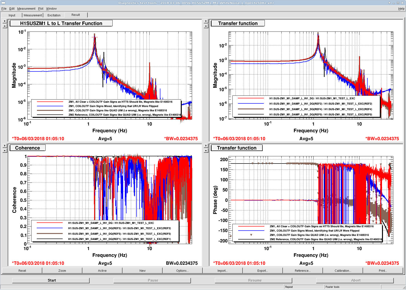
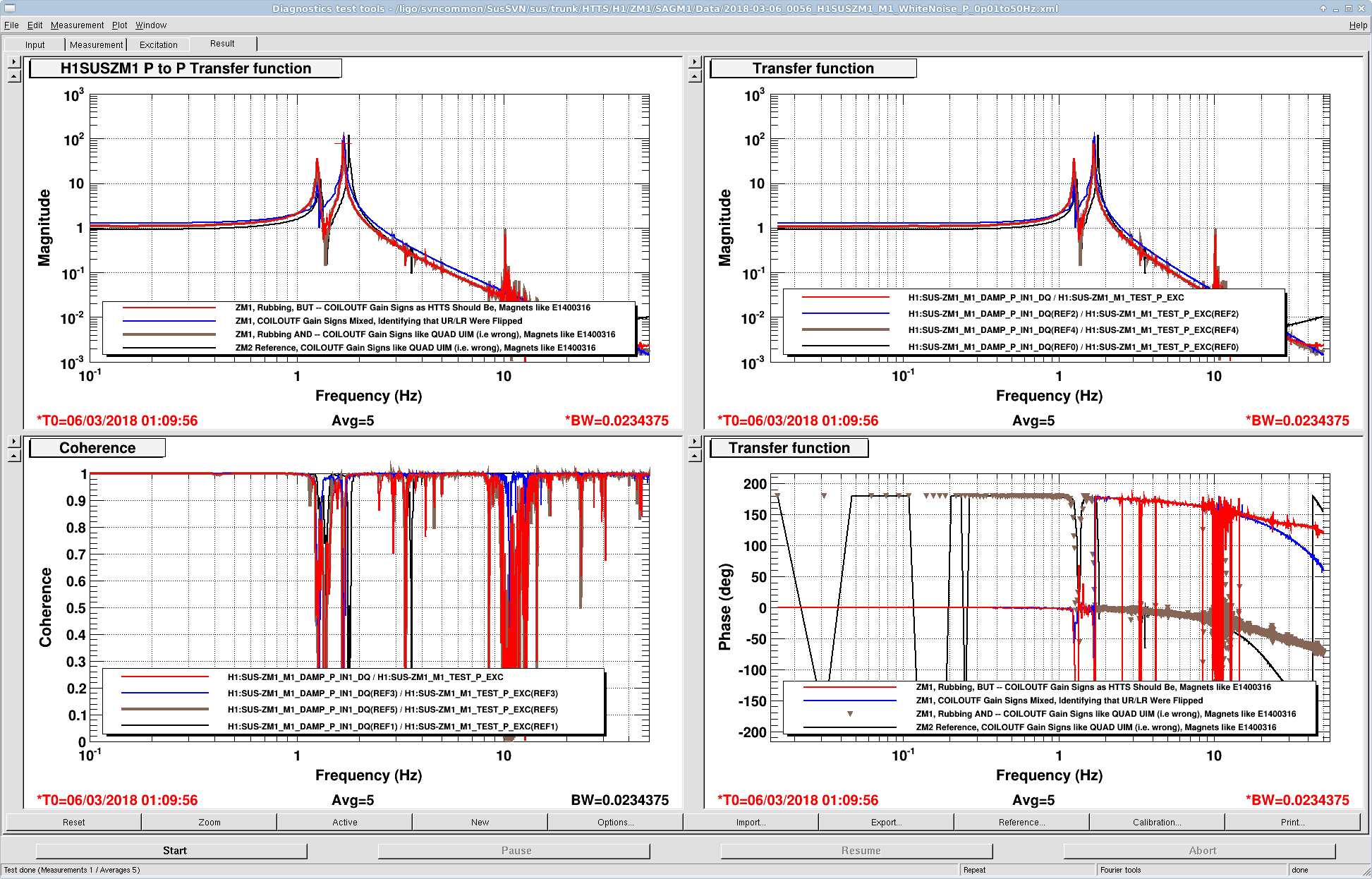
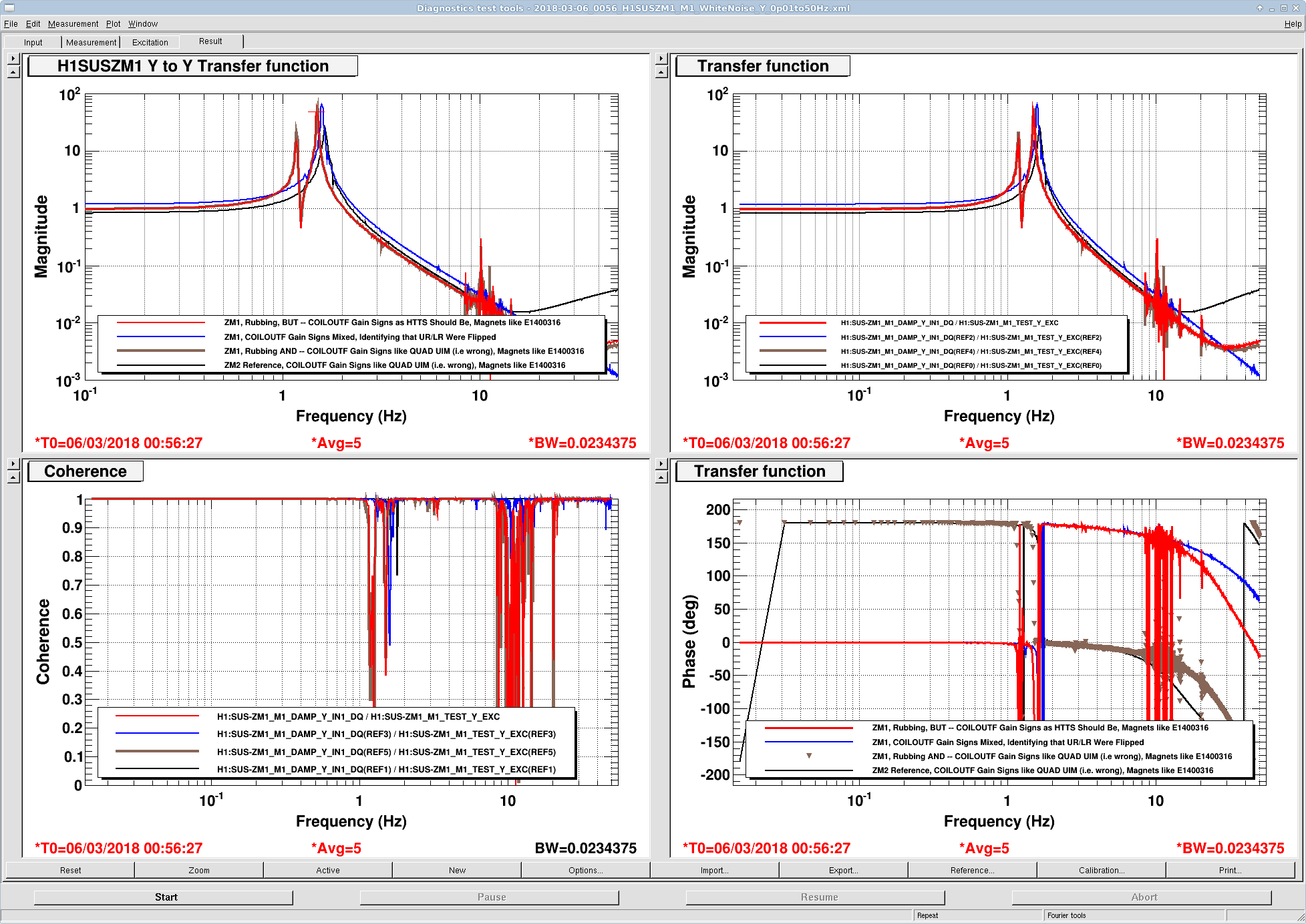
J. Kissel

During the teething period for ZM1 (for most relevant aLOG see LHO aLOG 40847), I've identified that I have been mistakenly and blindly installing COILOUTF gains for the HTTS (Ham Tip Tilt Suspensions; OM1, OM2, OM3, RM1, RM2, ZM1, ZM2) that match the magnet configuration of a QUAD UIM (E1000617) instead of what they've been built to be (E1400316), which is exactly opposite the QUAD UIM. Thus, damping loop feedback gains have been positive for quite some time.

I have now remedied this flaw in sign allocation on all** HTTS, and saved the the change into the SDF system (and committed the safe.snaps to the userapps svn).
This has three main benefits:
    - The COILOUTF signs vs. Magnet polarities are now consistent with other BOSEMs / magnet systems.
    - Each DOF's M1 to M1 transfer functions now show an overall 0 [deg] phase at DC, and decreases to -180 [deg] above resonance as one expects from a single-stage suspension.
    - The allocation of signs understandable from a simple logic thread, as defined in T1200015.

Just to be explicit, the correct COILOUT gains are

    UL = +1 (for N), LL = -1 (for S), UR = -1 (for S), LR = +1 (for N).

and all feedback damping loop gains are -1.

** All excludes RM2 -- because it has always had the opposite damping loop sign as the other (now) 6 HTTS. I suspect it's because RM2 *actually* has its magnet polarities incorrectly in the QUAD UIM BOSEM configuration. Thus, I've left the COILOUTF in the configuration to compensate for it, this way we're correctly compensating for the incorrect magnet polarities, and we can have a negative feedback gain on the damping loops like every other HTTS. Thus, for RM2 only,

    FOR RM2 ONLY UL = -1 (for S), LL = +1 (for N), UR = +1 (for N), LR = -1 (for S).