jeffrey.kissel@LIGO.ORG - posted 13:42, Thursday 01 March 2018 - last comment - 14:07, Thursday 01 March 2018(40789)
H1 SUS ITMY Still Occasionally Needs 50000 ct Vertical Offset due to Temperature
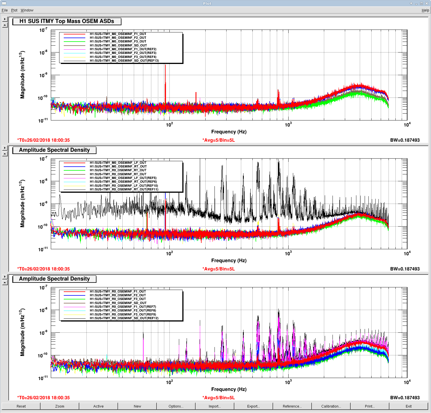
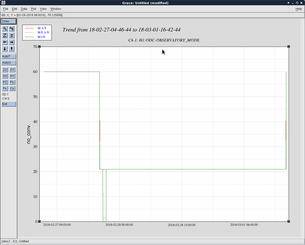
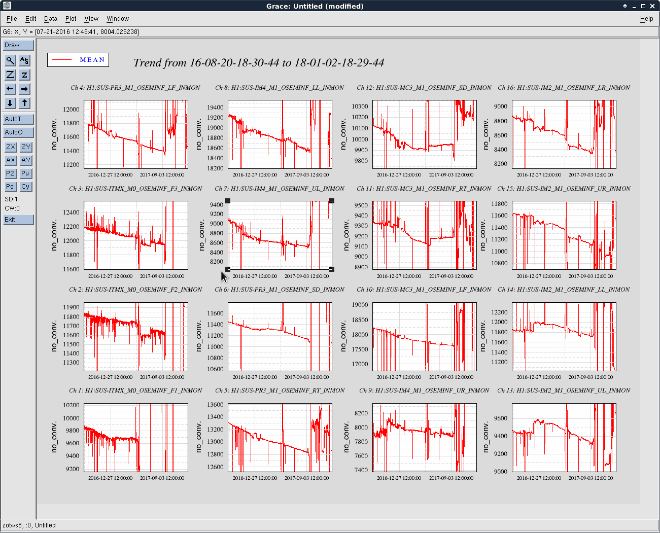
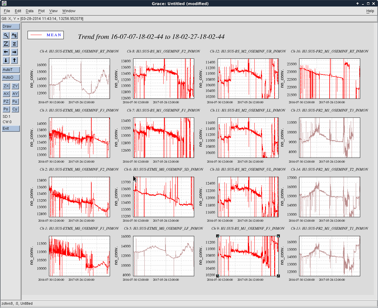
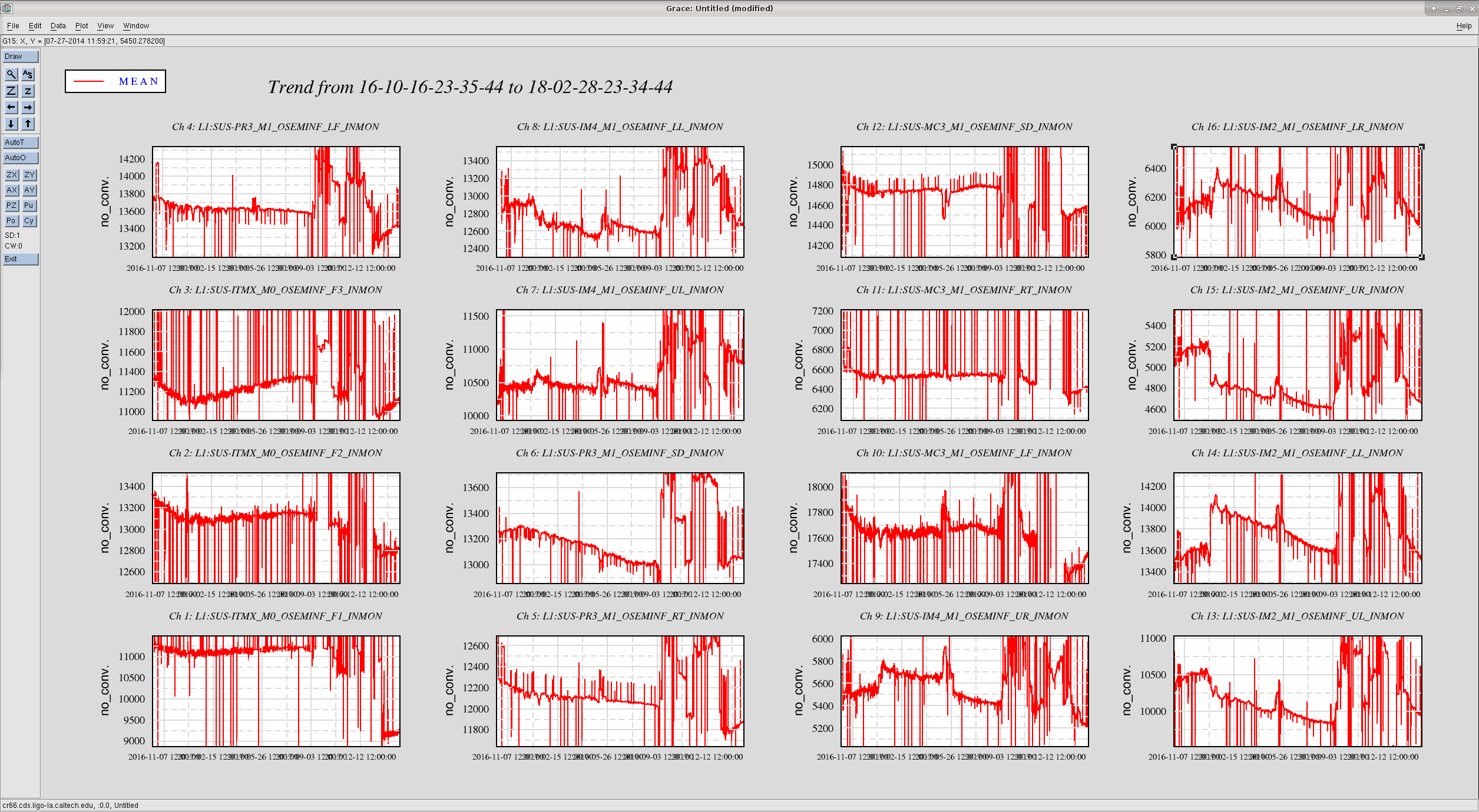
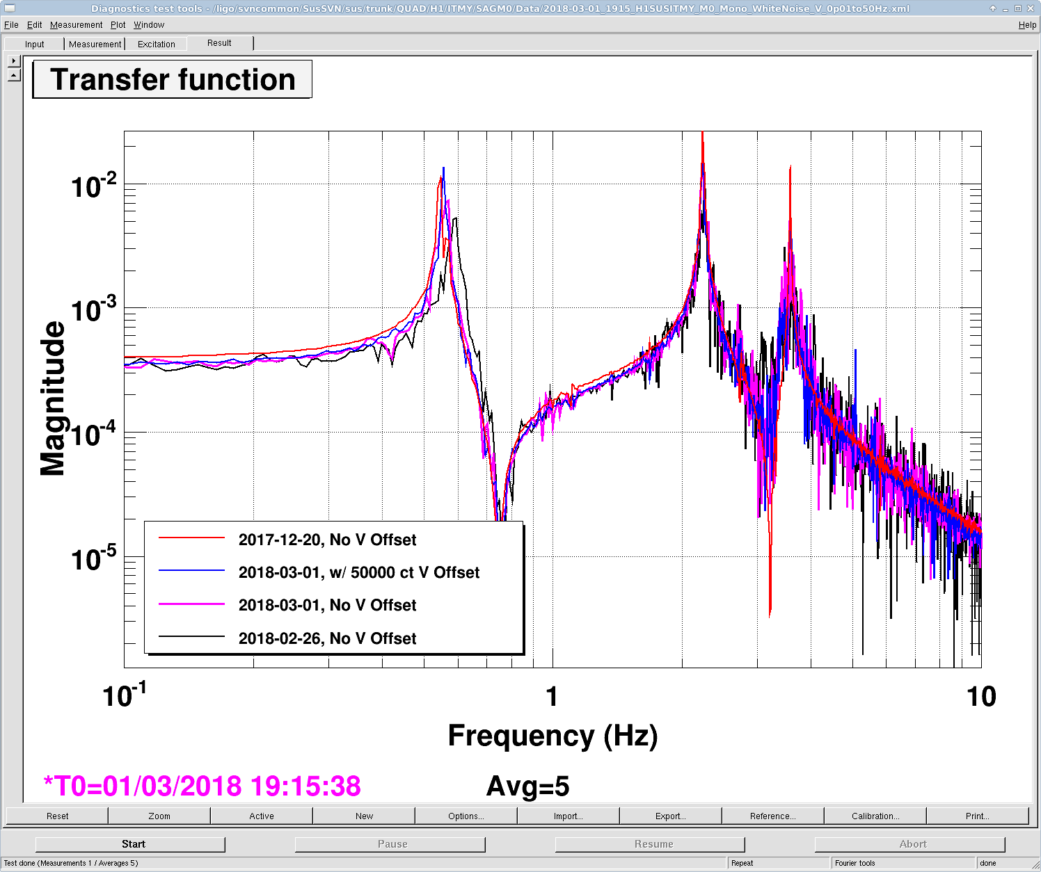
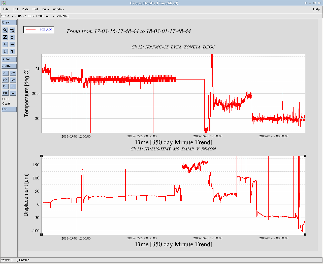
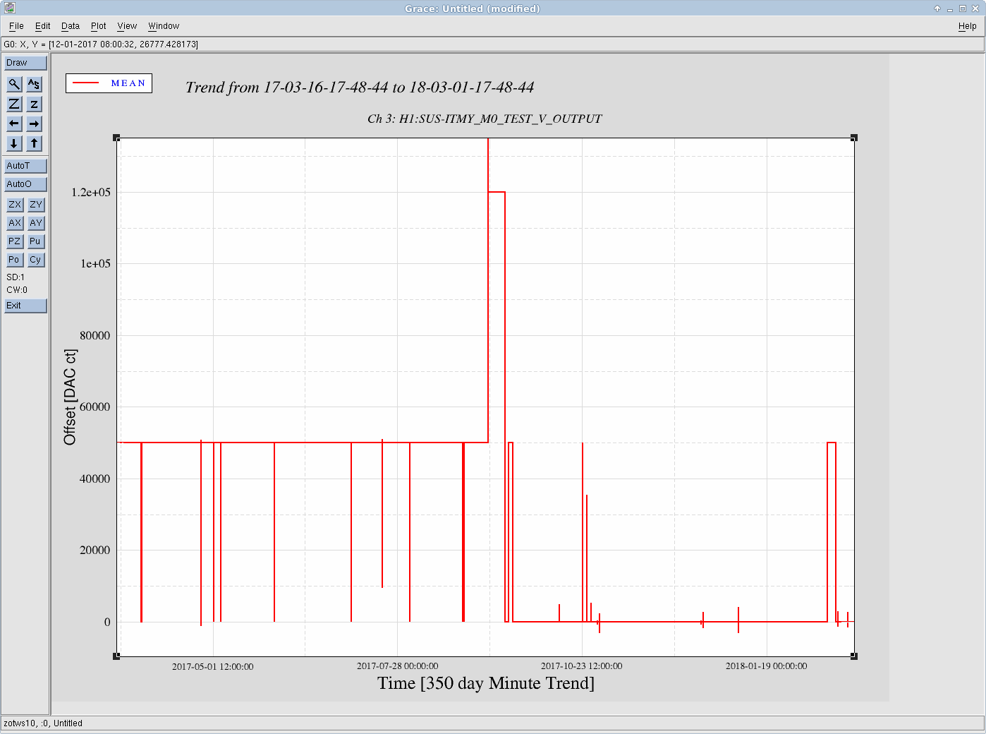
J. Kissel

While confirming the at-vacuum driven health of H1SUSITMY, I've found that -- although we've cured the RO RT OSEM shorting problem (LHO aLOG 40787) --  the main chain (M0) still *sometimes* needs as 50000 ct vertical offset in order to prevent noisy, potentially rubbing-like V and R transfer function results. I say *sometimes* because I measured the M0 V and R TFs on 2018-02-26, saw noisy results, and the first vertical mode was ~0.04 Hz higher than expected. Suspecting that we still needed the 50000 ct vertical offset that was used during most of O2 (I couldn't find an aLOG to reference), I turned ON the offset, measured V and R (and the rest of the DOFs) today, 2018-03-01 and saw that the TFs cleaned up nicely with the 1st vertical mode in the right place. But -- just to be sure -- I took the V transfer function again *without* the offset, and saw that the transfer functions still look acceptable.

The first attached image shows the results and what I mean regarding "noisy". Hopefully the legend straight-forwardly labels the above described measurements.

With these initially confusing results, I started trending temperature and vertical positions of corner-station BSC suspensions.  The history: after the short vent to repair the ITMY R0 RT OSEM, the vertical position dropped to ~ -100 [um], then at 2018-02-26 08:58 UTC (about 01:00a PST local!!), shot up to ~ -80 [um], stayed there until 2018-02-27 20:55 UTC, then it began to exponentially continue to rise to pre-vent quick-vent value of ~ -50 [um]. The 2018-02-26 measurement I took happened to be in the ~1.5 day 80 [um] time, where I suspect the suspension was/is just subtly rubbing like it was in O2 that drove whomever to add the 50000 ct V offset originally.
I also show a 50 day trend of all BSC SUS. All suspensions show the same vertical position evolution as ITMY, indicative of a corner-station-wide, in chamber temperature trend, not something quirky about ITMY.
The in-loop, averaged corner station temperature sensor for Zone 1A near the BSCs reports a flat temperature for many moons, not unexpectedly.
The vertical position of ITMY during the extra clean 2017-12-20 measurement was +30 [um]. That measurement was taken in air, just before the doors went on over the holidays (see LHO aLOG 39829) -- showing that if the suspension is riding high due to cool temperatures, it's possible to get a very clean transfer function, even at air, so something is clearly interfering / rubbing / messed up when the SUS runs hot.

Frustrating. Especially, and probably because, it's intermittent -- we forgot about the need for this offset, and didn't address it either times we opened up BSC1 to play with ITMY. And we *always* forget about temperature during the chaos of a vent. Stinks.

So, for now, I leave the 50000 ct offset in place (this is about 1/4th the range of the DAC), but we should continue to watch this suspension with respect to vertical position and temperature, hoping that it regains more of its vertical position and continues to improve whatever is going on.

The .pdf attachments show the full suite of M0 and R0 transfer functions taken on 2018-02-26 when the main chain was low / rubbing, and on 2018-03-01 when the 50000 ct vertical offset was applied (and the temperature had risen a bit) showing clean transfer functions. I did not take a full suite today (2018-03-01) without the offset.

On a happier note that the Reaction (R0) chain looks clean after the repair of the R0 RT OSEM. And for the record, the attached results are with and without the 50000 ct main chain V offset, and they show no difference -- implying that whatever is going on with the Main Chain is an independent problem.
Images attached to this report

Non-image files attached to this report

Comments related to this report
Opened corresponding FRS Ticket 10081.