[Georgia, TVo, Sheila, Jenne]
Summary: We were able to lock and align the Xarm and input beam for both green and IR.
This morning, we locked Xarm with the green laser, and aligned TMSX, ETMX and ITMX to the green beam. As usual, PR3 was adjusted to get the transmitted green beam out onto ISCT1. (The ALS light pipe was also opened.) The ALS WFS didn't end up working for us today - the yaw signals seemed to make sense, but the pitch signals didn't really. We decided to move on rather than investigate this in detail. The TMS and ITM pointing were both set using the bafflePD alignment script, then ETMX was adjusted to maximize the transmission through the cavity.
After lunch, we succeeded in moving IM4 and PR2 to get the IR beam aligned to the Xarm.
We ended up using LSC-POP_A_RF45_I to lock the Xarm, rather than the planned ASC-AS_A_RF45_I_SUM. POP has worse SNR, but seemed to work a little bit better. We did not go back and re-try to use AS_A after the cavity was well-aligned, but we need to check and confirm that the signal path is doing what we think it is, sometime using MICH (it all looked fine, and was going to Xarm_IN1, but we just weren't catching any good locks). We used an input matrix element of -10 for POP, so that the XARM_IN1 was the same roughly +-200 counts that it was during O2 initial alignments of Xarm-only flashing with the old ASAIR_RF45. Otherwise all the Xarm locking settings were as in guardian.
We had some struggles throughout the day, see in particular Sheila and Georgia's alogs. TVo is summarizing our Xarm visibility measurement in yet another alog.
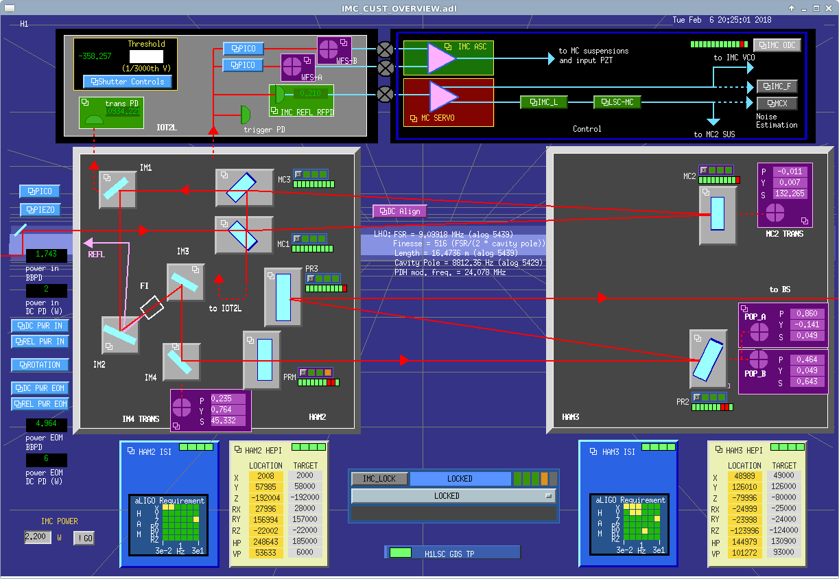
Attached is our alignment after the arm peek. IMC WFS were on, but no other ASC is engaged. I also attach the IMC overview, for the IM4 trans and POP_B values, so we don't have to trend them later.
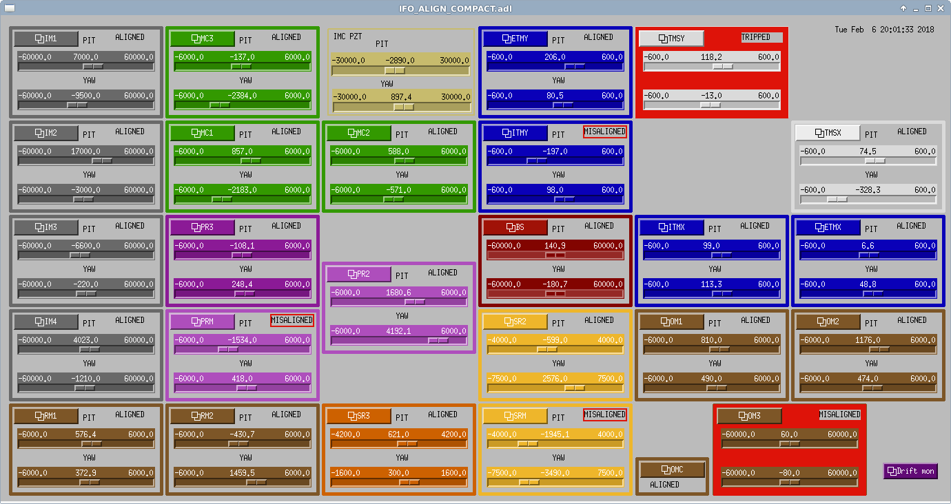
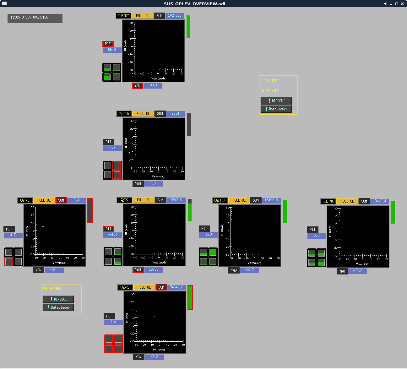
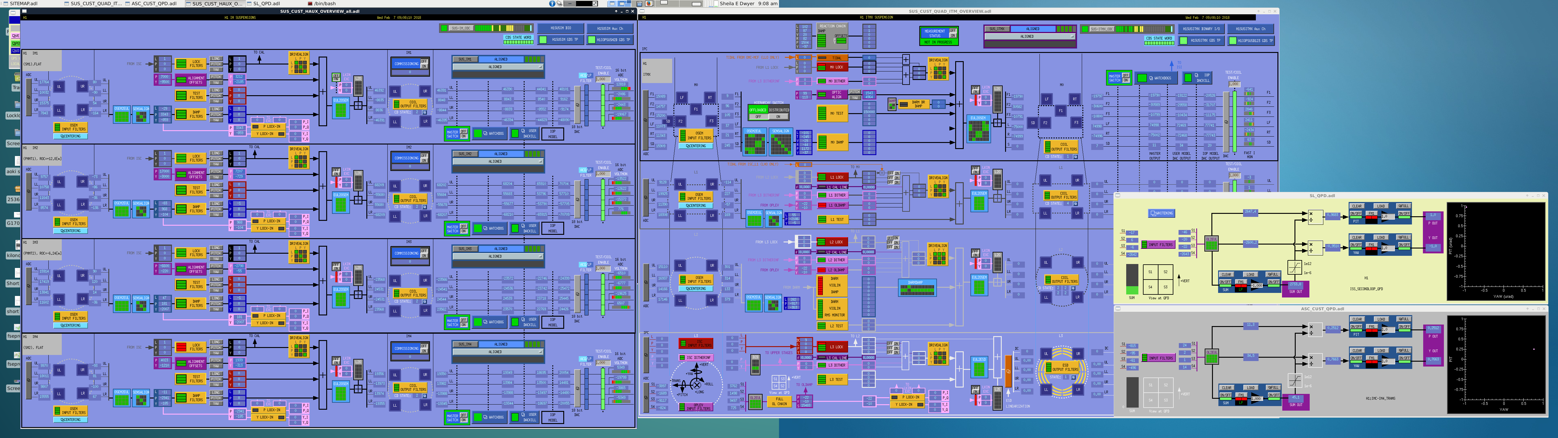
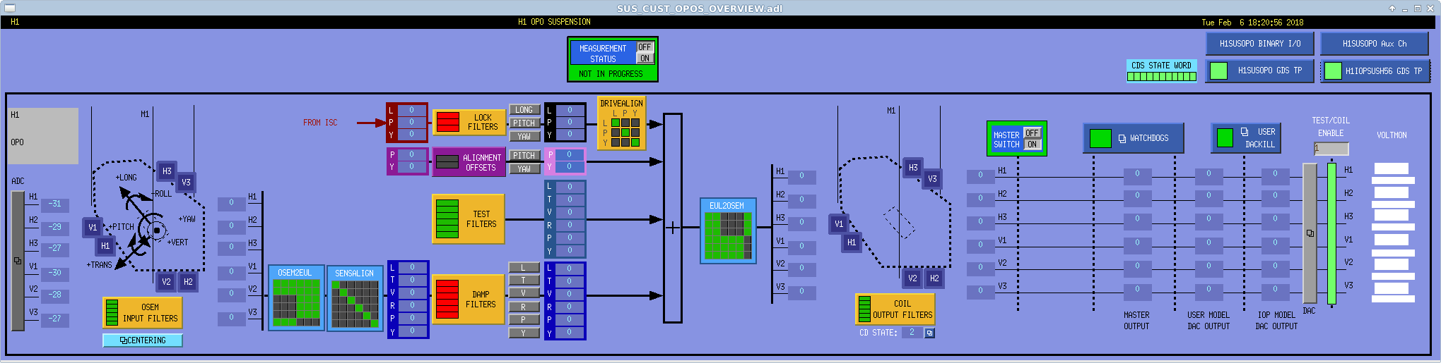
Attached are screenshots showing the ITMX suspension overview, the IM overview, and spot positions on IM4 and the OSS QPD (which the beam is not on right now) and the oplev overview after yesterday's alignment, in case this information is useful in addition to the slider values.
Also, after locking the X arm in green we also adjusted PR3 to maximize the comm beatnote on ISCT1 which has not moved since O2. The final alignment of IR into the X arm was done with this PR3 alignment.