I've taken a first look at the data that Camilla and Matt took in https://alog.ligo-wa.caltech.edu/aLOG/index.php?callRep=85813.
In the past, I've started modeling these data sets by assuming a fixed arm power, and finding IFO readout losses that are needed to fit the measured shot noise without squeezing at 2kHz. This time, inspired in part by a comment from Begum, I instead used only the known IFO readout losses and attributing the rest to mode mismatch between the IFO and OMC, this allows us to make an upper limit on the mode mismatch from the IFO to the OMC.
From the google sheet , I will include SRC losses as a known readout loss (although the are listed as sqz injection losses, I think for the IFO they are readout losses), 0.99(SRC)*0.995(OFI)*0.9993(OM1)*0.985(OM3)*0.9904(QPD)*0.956(OMC)*0.98(QE) = 10% known readout losses. The known injection losses (not including SRC losses) are then 0.985(OPO)*0.99^3 (3 SFI passes)0.99 (FC QPDs)*0.99(other HAM7 loss) *0.99 (OFI)= 7.2%
Fitting the level of squeezing and anti-squeezing at 2kHz suggests an NLG of 13.2 (fairly close to Camilla's measurement of 13.4), and a total efficiency of 0.752 using the Aoki equations (treating mismatches as losses). Looking at the interactive sqz gui, the IFO to OMC mismatch reduces the measured sqz anf anti squeezing at 2kHz, but the mismatch phase only has an impact below about 400Hz.
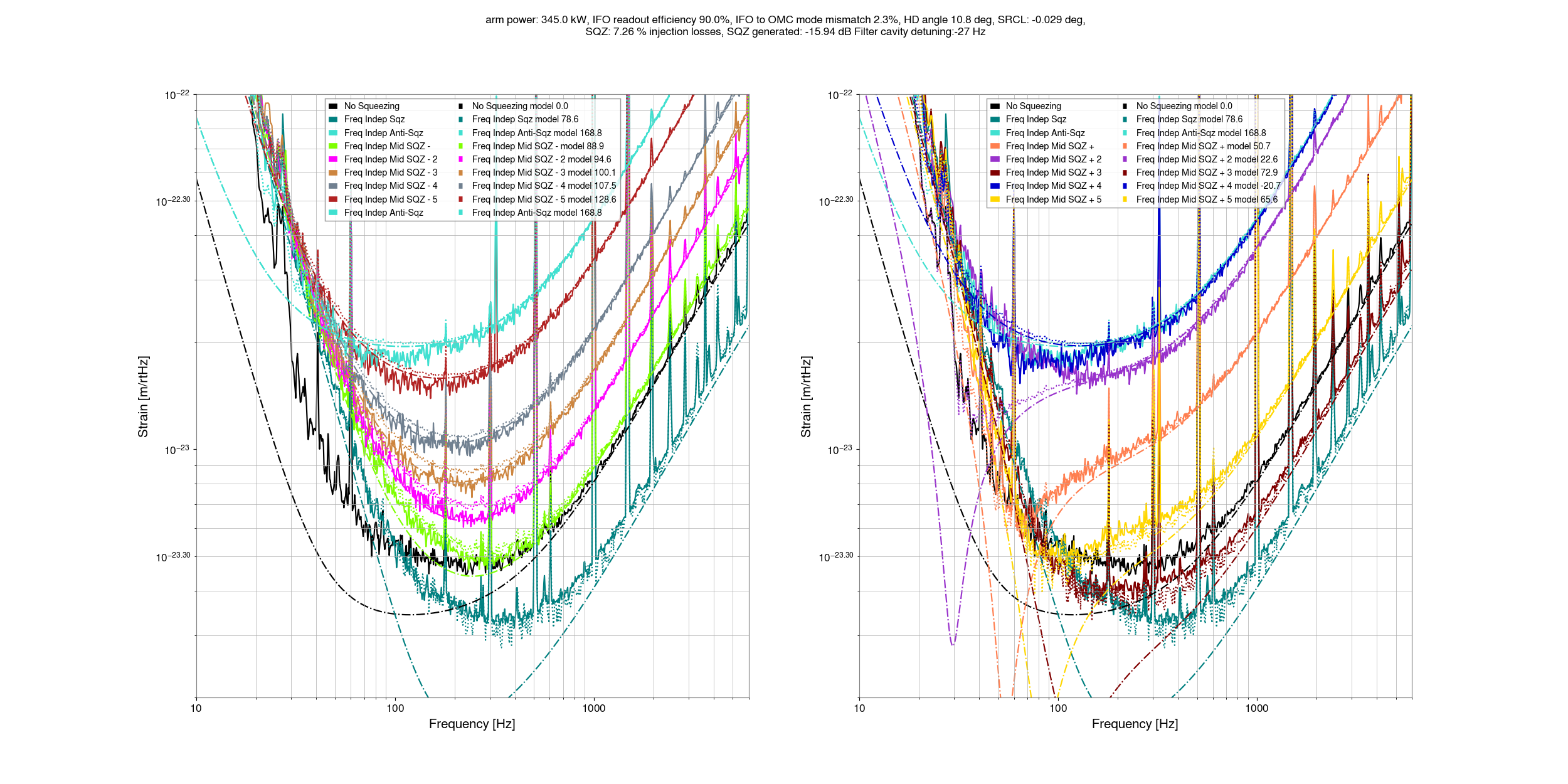
Using only the known readout (10%) and injection losses (7.2%), perfect sqz to OMC mode matching, we can get some limit on the amount of OMC to IFO mode mismatch that can be compatible with our 2kHz squeezing. 5.1% mismatch (which would imply 355kW in the arm cavity) seems too high to be compatible with our squeezing, while a mode mismatch of 3.7% with 350kW in the arm does seem compatible if the sqz to OMC mode matching is perfect. So, we can take 3.7% as an upper limit on the IFO to OMC mode matching that is compatible with known squeezing losses. The data could be compatible with mode mismatches as low as 2.3% (345kW in arms) without introducing any extra losses. Any unknown squeezer losses, like excess crystal losses, will reduce this amount. The arm power of upper limit that we'd infer from this is 350kW, but this depends sensitvely on what we assume the non quantum noise is at 2kHz. I will try to redo this estimate soon using the cross correlation data that Elenna is working on to have more confident limits on the arm power.
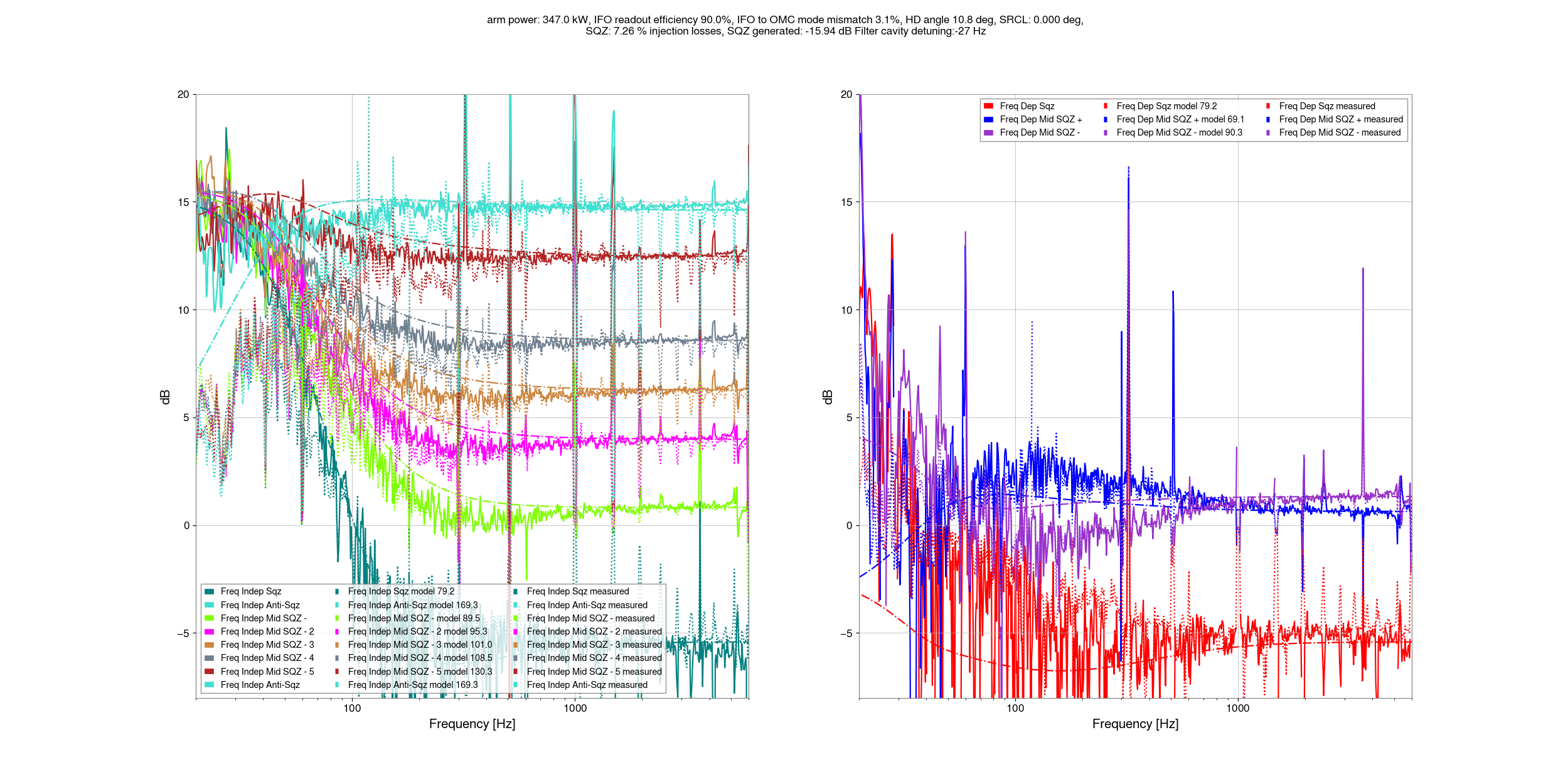
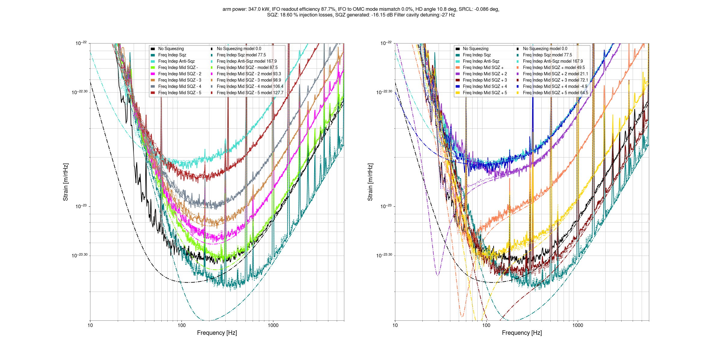
These first two plots show that this model isn't well tuned at a few hundred Hz, I haven't tried to set either the SRCL offset or homodyne angle yet, or the OMC to IFO mismatch phase. At first glance it does not seem like I will be able to make this match well by adjusting the mismatch phase.
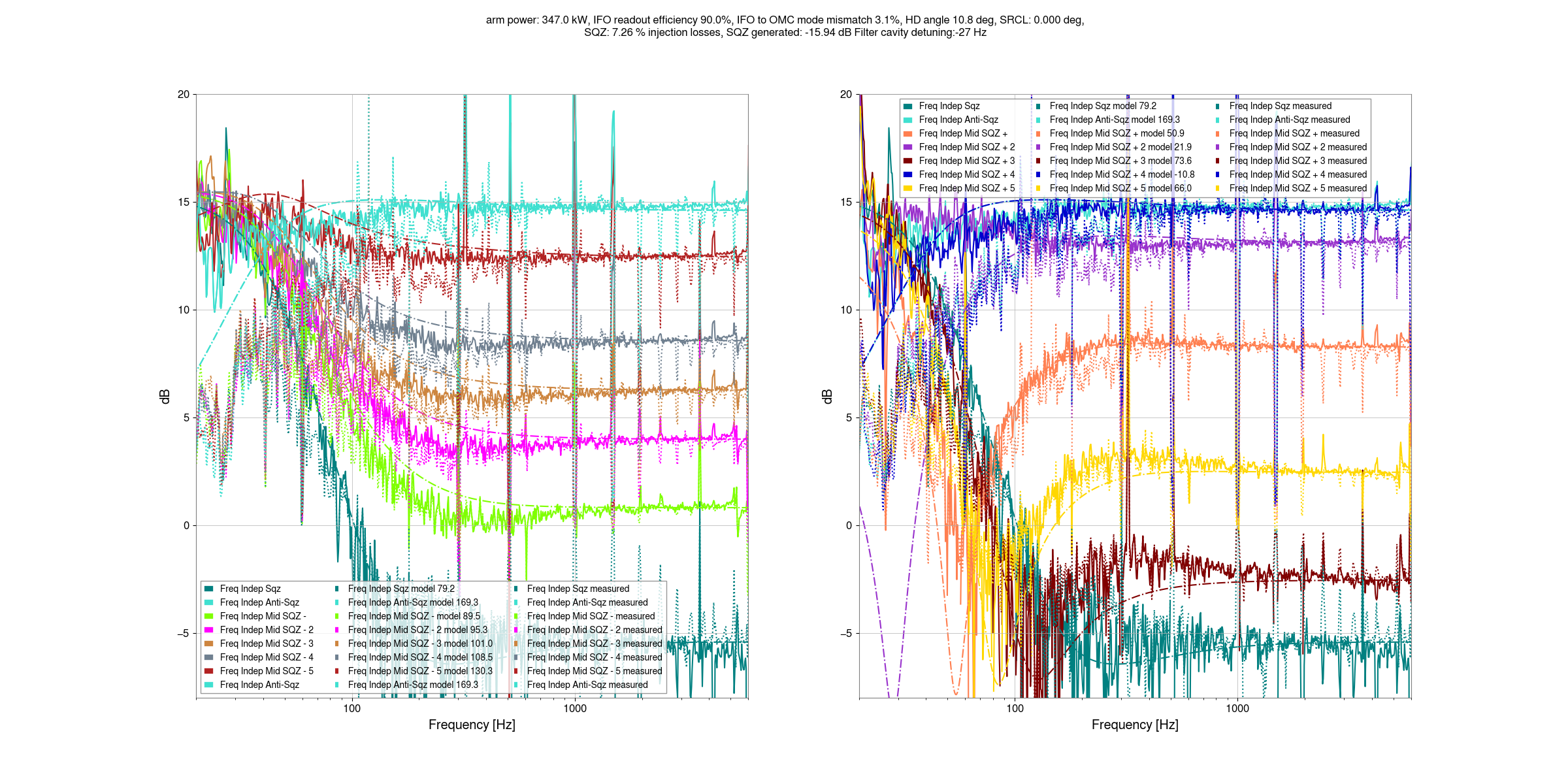
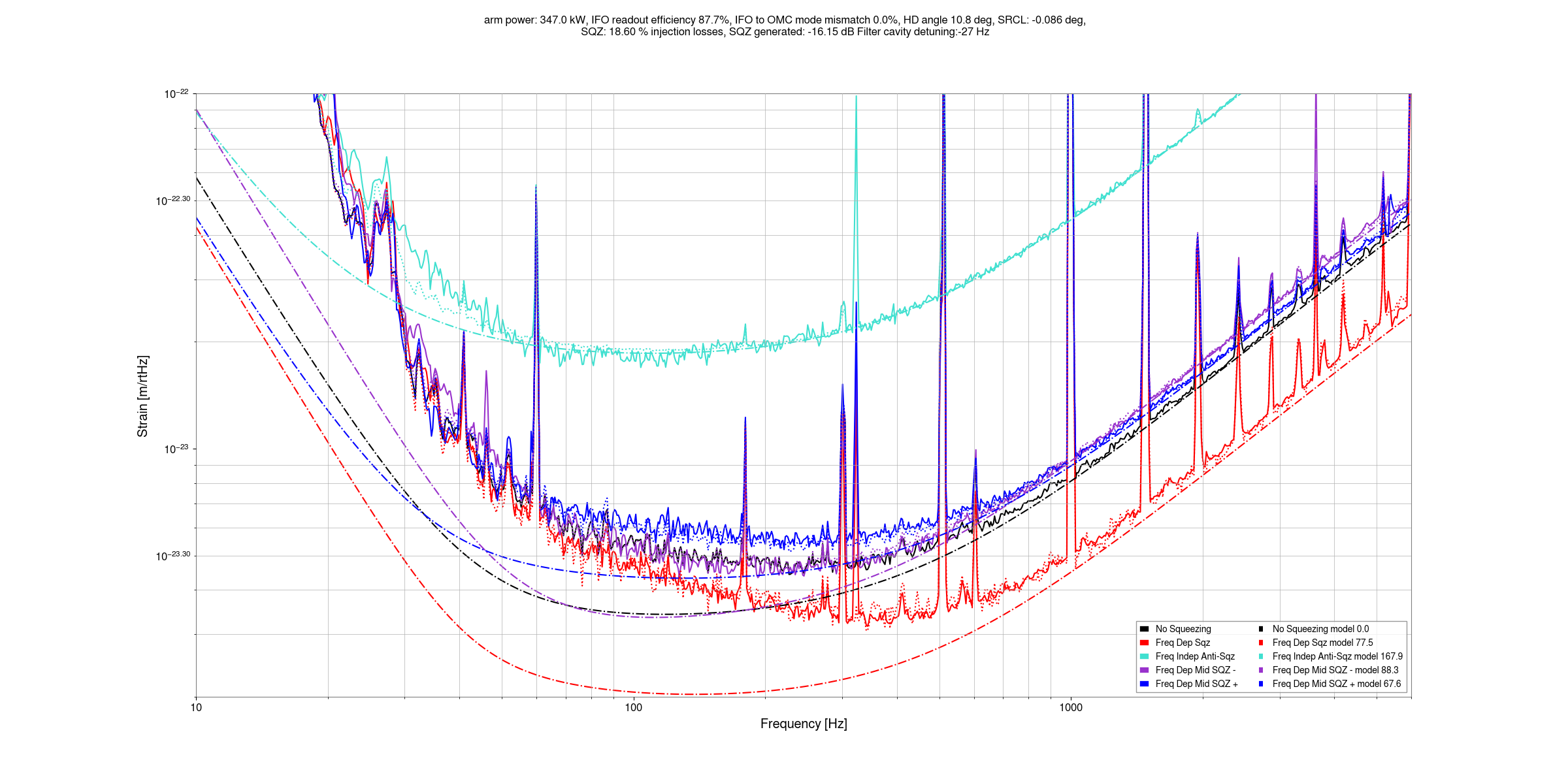
The last two plots show the squeezing level in dB, just so that we have a plot we can look at. The script to make these plots are committed here