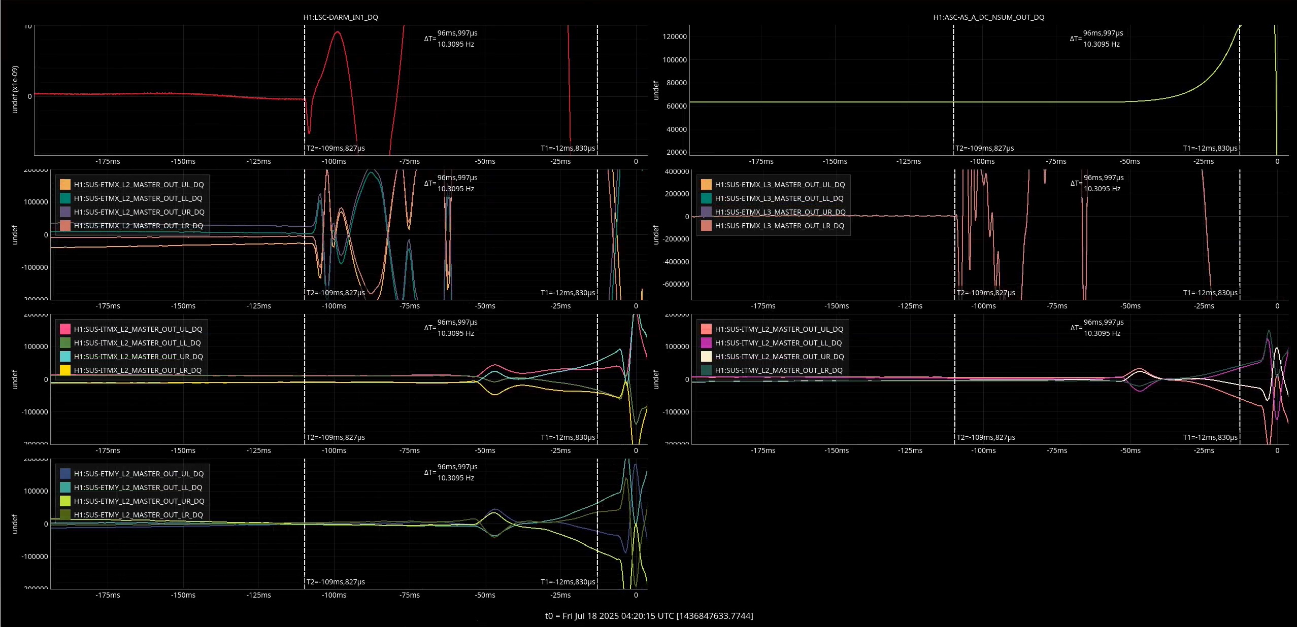
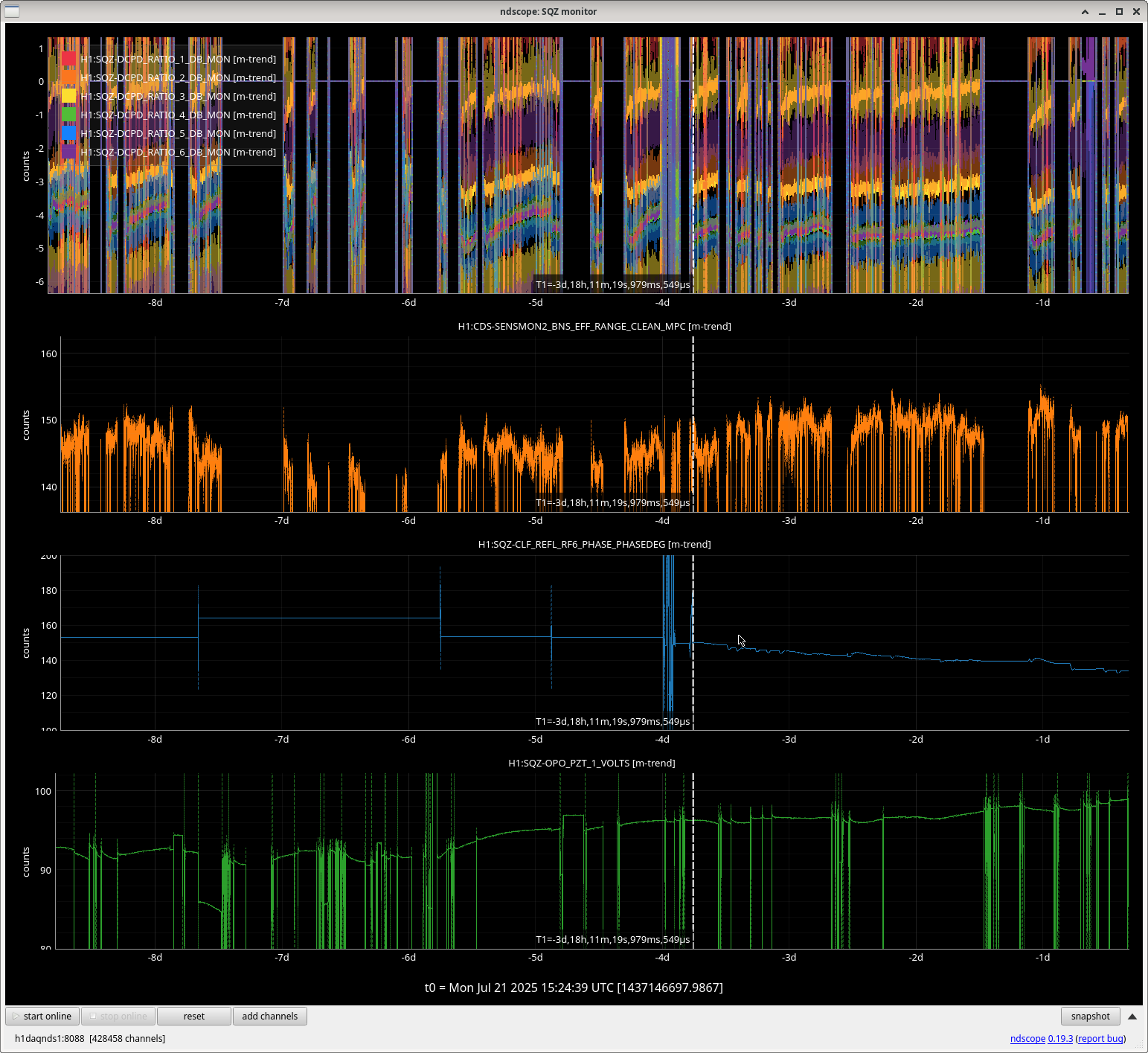
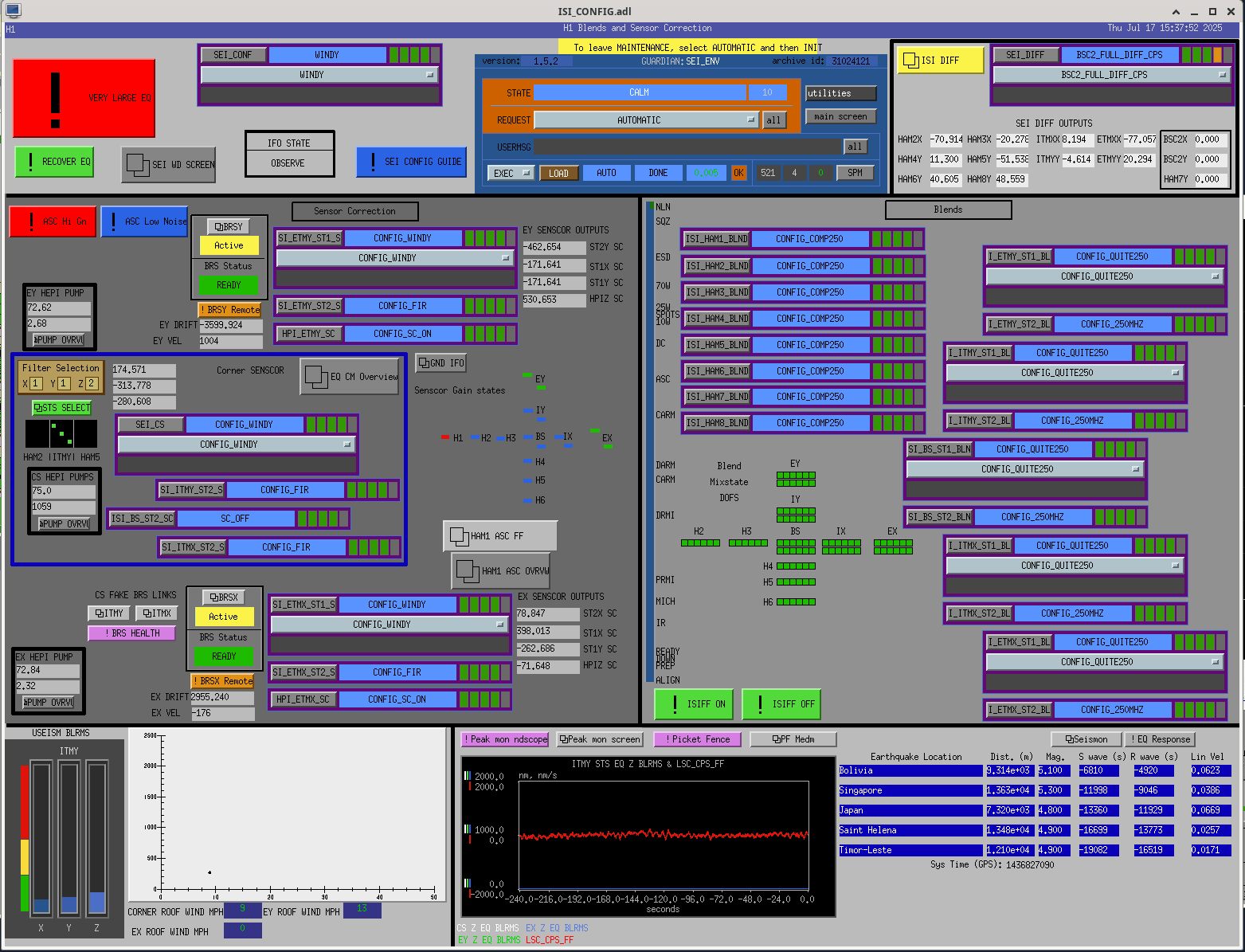
We had a 6.6 earthquake begin rolling in from Panama, so Jim and I tried to take the ASC arm control loops to the high bandwidth state. I also turned off the LSC feedforward which drives the ETMY PUM.
This obviously creates a lot of noise in DARM, but we are curious to see if it helps us ride out a large earthquake.
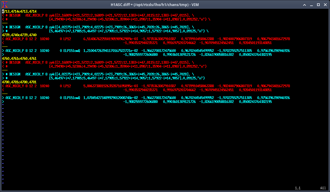
Some of these things can be done by hand, but others, like transitioning filters and gains together have to be done with guardian code to ensure they are done at the same time. I copied and pasted lines of code into a guardian shell.
ezca.get_LIGOFilter('ASC-CHARD_Y').ramp_gain(300, ramp_time=10, wait=False)
ezca.switch('ASC-CHARD_Y', 'FM3', 'FM8', 'FM9', 'OFF')
ezca.switch('ASC-DHARD_Y', 'FM1', 'FM3', 'FM4', 'FM5', 'FM8', 'OFF')
ezca.switch('ASC-CHARD_P', 'FM9', 'ON')
ezca.switch('ASC-CHARD_P', 'FM3', 'FM8', 'OFF')
ezca['ASC-CHARD_P_GAIN'] = 80
ezca.get_LIGOFilter('ASC-DSOFT_Y').ramp_gain(30, ramp_time=5, wait=False)
ezca.get_LIGOFilter('ASC-DSOFT_P').ramp_gain(10, ramp_time=5, wait=False)
ezca.switch('ASC-DHARD_P', 'FM4', 'FM8', 'OFF')
ezca['LSC-PRCLFF_GAIN'] = 0
ezca['LSC-MICHFF_GAIN'] = 0
ezca['LSC-SRCLFF1_GAIN'] = 0
I saved this as a script called "lownoise_asc_revert.py" in my home directory. This is a bit of a misnomer since it also reverts the LSC feedforward.
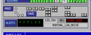
We are still locked so far, but we are waiting to see how this goes (R wave just arrived).