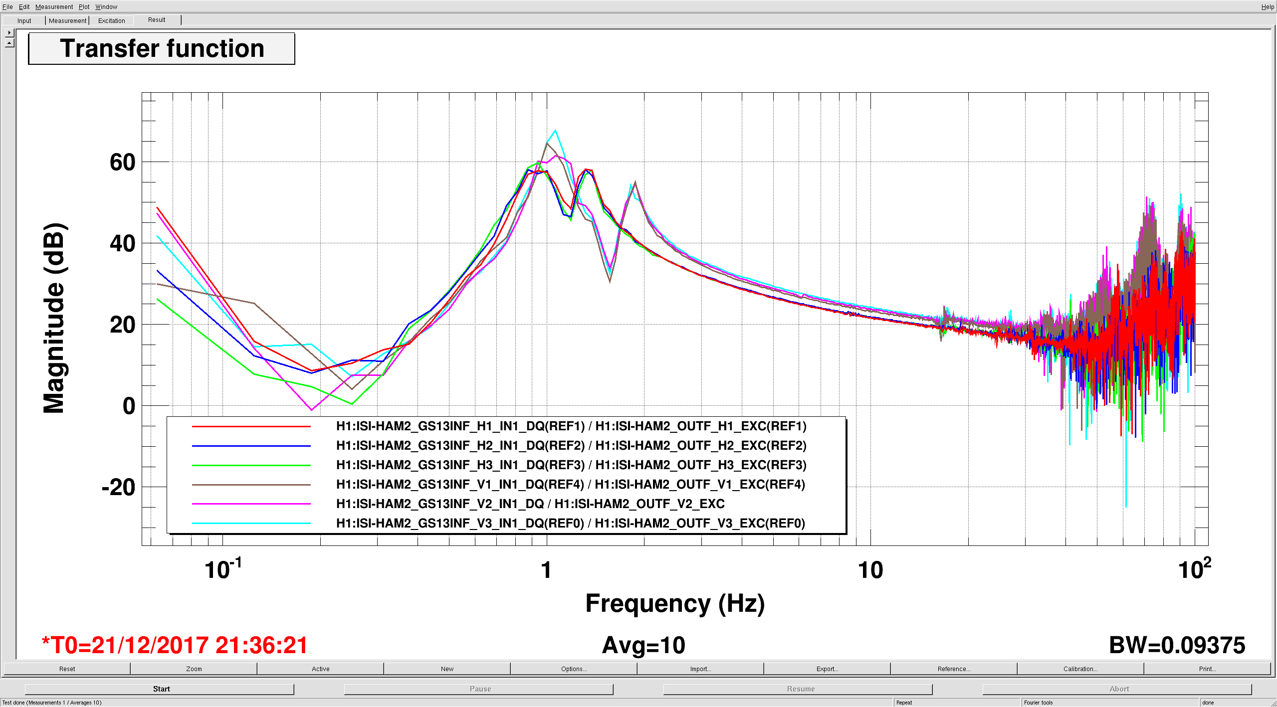
WHAM2--This platform had not been unlocked for some time, ~Nov 6 when Jim did TFs.
After unlocking, balanced the tilt as close as possible to the locked position of the last few days. Limited mass choice and position only allows getting so close.
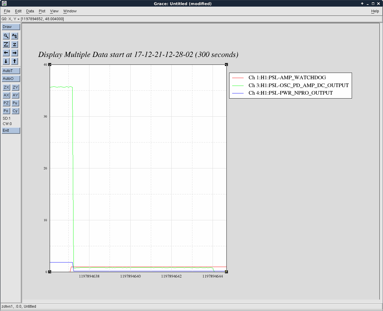
After Jim ran TFs today, the free hanging positions are 41, 7, & 96 urads for RX, RY, & RZ. The positions while locked the last few days have been 43, 8, & 82 urads. So the Tilt are very close but the RZ difference is some 14 urads. Sadly, we can't do anything about the RZ now. The solution should be that when we first vent, give SEI some time to adjust the lockers to minimize this--probably a day or two at least. And, as the payload changes and the platform is climbed on, this free hanging/locked position difference will change further. We can do two things now going forward, servo RZ to the locked position which might make the ISI Isolation loops turn-on a bit touchy, or, as SEI would prefer, servo to the free hanging position and we'll see if IO notices/cares. Alternatively, if the ISI is touchy and IO does care, we can twist the platform with HEPI--which we are perfectly happy to do. For what it is worth, when Jim had the platform unlocked for the TFs in early November, the RZ position was similar to now.
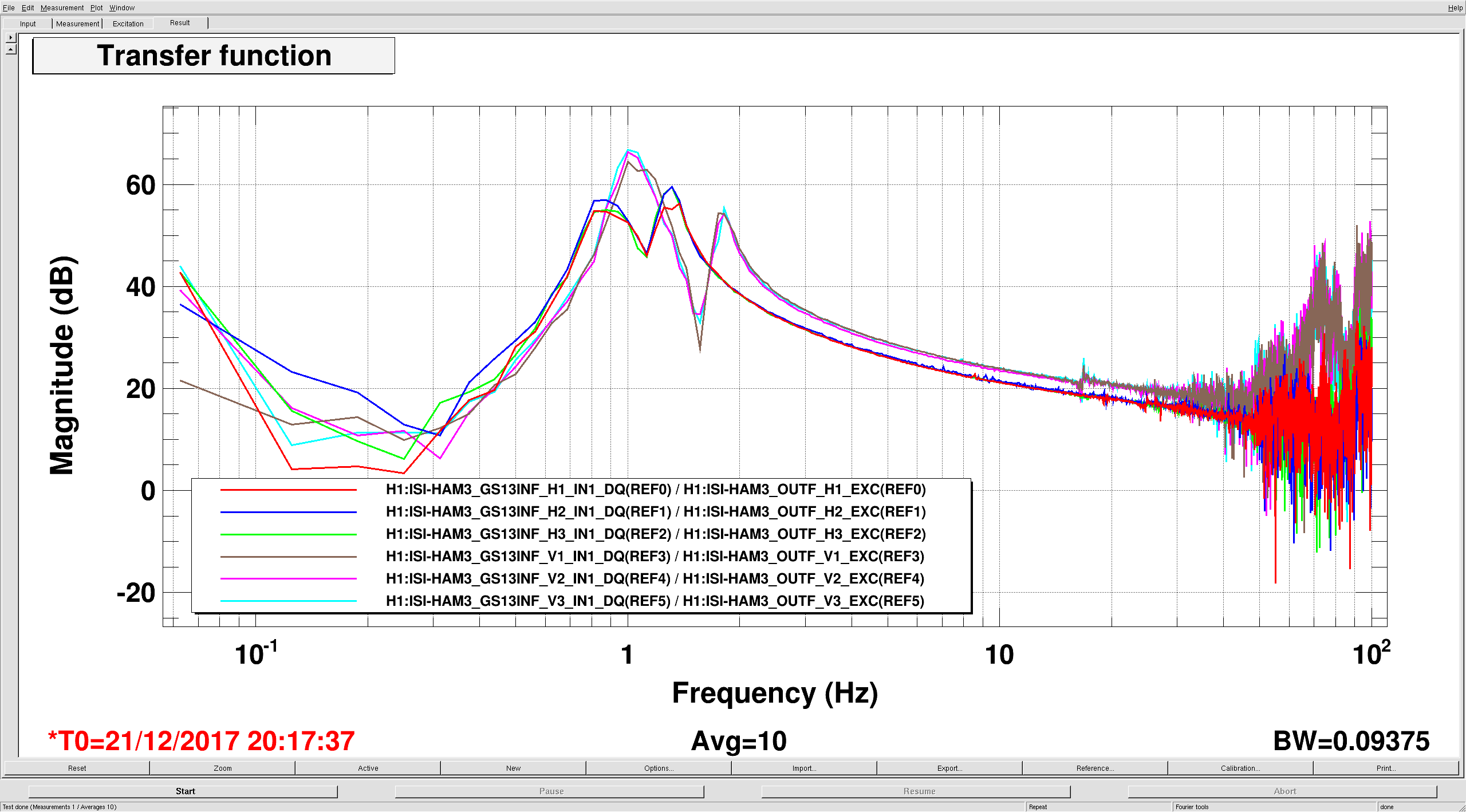
For WHAM3--Comparing the locked position over the last couple days to the last couple months, the tilts and RZ are consistent: -6, -6, & -5 urads for RX, RY, & RZ. The current now free hanging positions are -9, -8, & 5 urads. So, similar to HAM2, the RX & RYs are within a few urads but the RZ has an ~10 urads twist when unlocked. Like HAM2, will let IO decide if this twist is too much and if so, SEI will decide if we can tolerate it on the ISI or if it needs to be offloaded to HEPI.
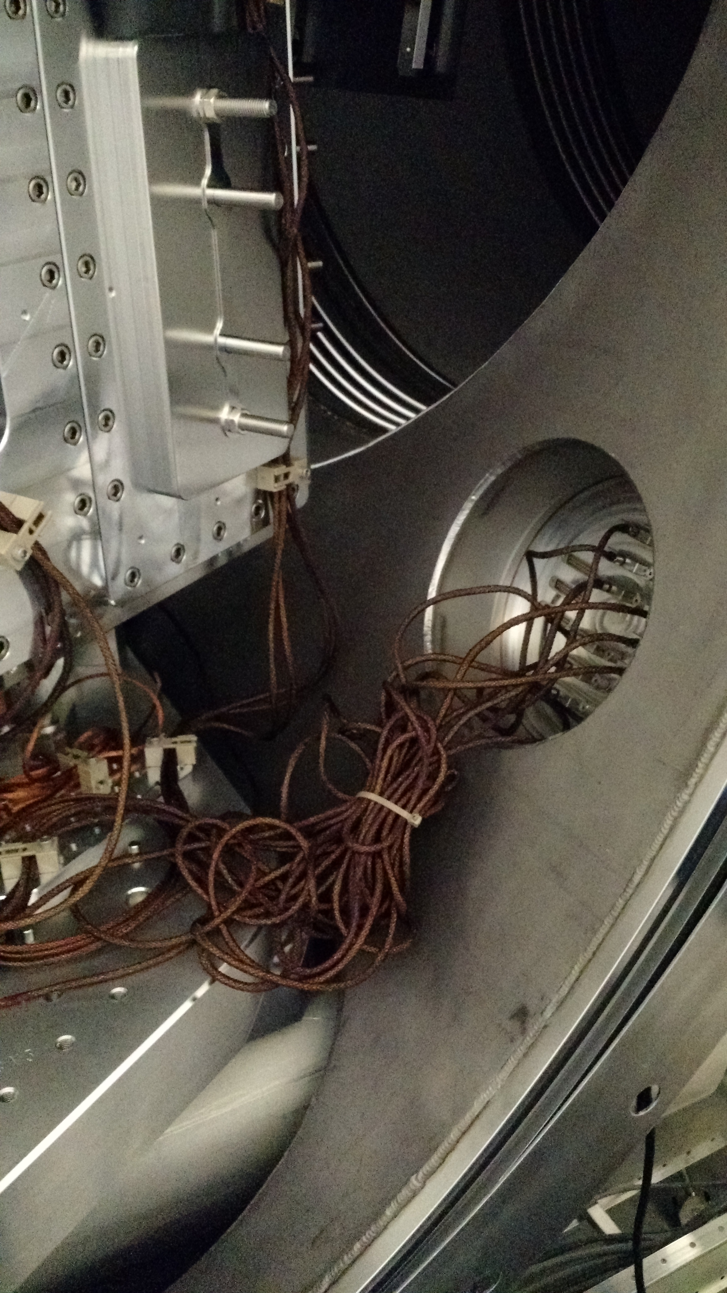
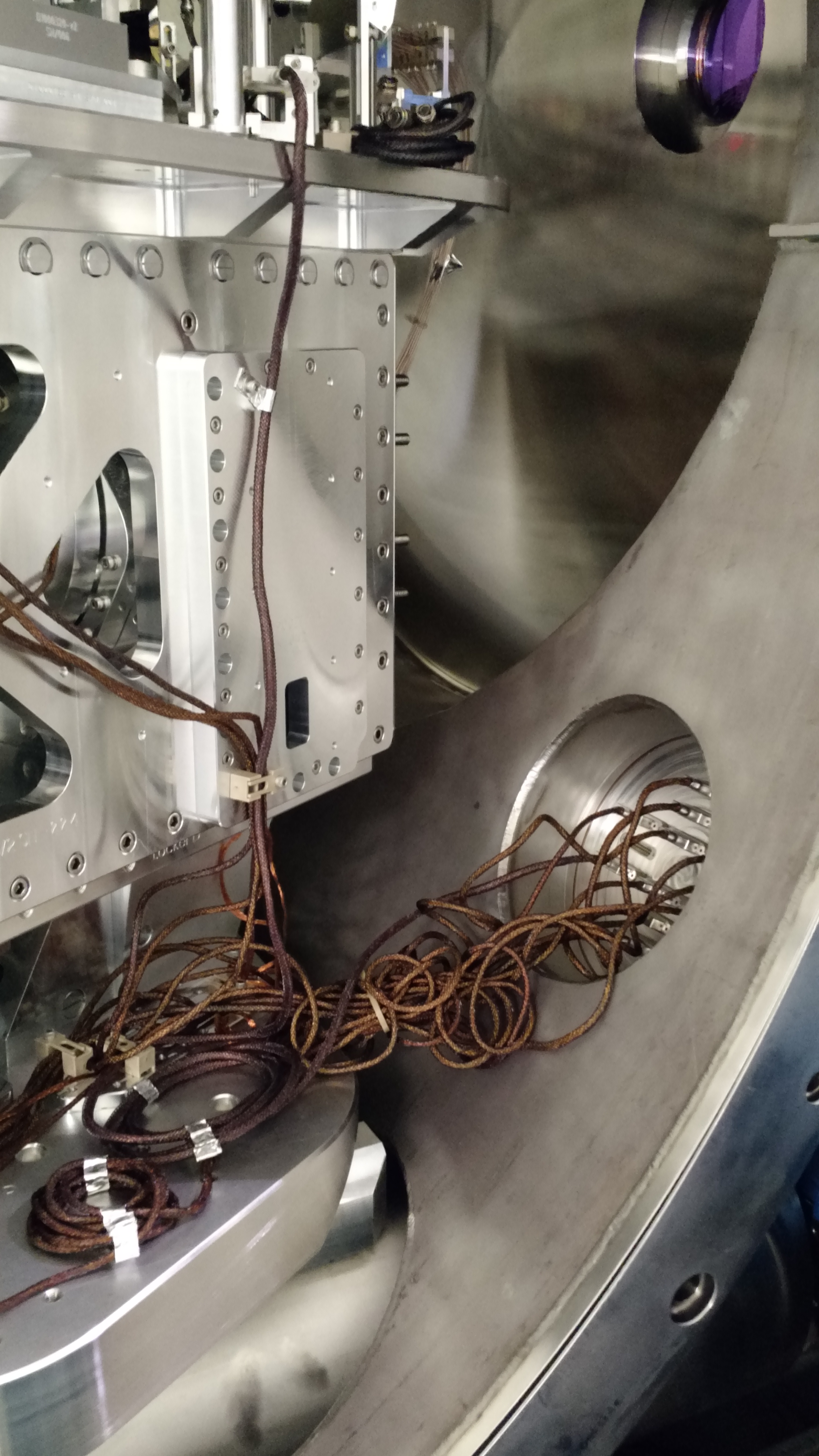
Attached photos show a couple of bundles of cables on the +X-Y and -X+Y corners of the ISI Stage0 of HAM2 heading to the chamber feedthrus. HEPI won't have any difficulty dealing with it now but may be an issue if we attempt any real isolation--could complicate the TFs. Maybe these cable bundles could be done differently if it seems to be a problem.