Noted that at about 10 am - 10:04 am PST on top of End Y, the anemometer was pointing to about 20 deg to the -Y of +x and that sensor is not moving very smoothly.
The sensor is on the upper roof, about 1/2 way along Y, and about 8 feet from the +x edge, and about 6 feet up.
10 am = 1196013618 for 600 sec - epics data says that EY is about 360. so this is = north
Perhaps the EY sensor is aligned with north, but need to recheck.
tconvert 11:00:00 pst -> 1196017218
at 10:59 am, the EX sensor was pointed in the +x direction. It then moved to point in the -Y direction.
at GPS time 1196017200, the direction reading for EX is 183 deg.
at ...17254, it moves up to 271 degrees. I think this means that EX wind direction is aligned with the observatory coordiatates. That wind coming from the +x direction reads +180, and wind coming from the -Y direction readys 270. This is not crazy, since wind blowing from -x towards +x would read 0.
The EndX direction monitor is moving smoothly. I also note that the black hat thing has come off. looks like it used to cover a wire wound resistor and a toggle thing. I do not know what it is supposed to do, but it will probably be happier with the cover replaced.
S. Dwyer, K. Kawabe, J. Kissel, B. Weaver, G. Moreno, C. Vorvick We've completed the by-hand alignment work needed with the PSL beam, picking up where we left off yesterday (LHO aLOG 39553). That means, we've reconstructed an alignment (using steps 1-11 in LHO aLOG 39547) to get a well-aligned PSL beam from the IMs, centered through SRM and coming out of the OFI well, and then repeated steps 12-14 from LHO aLOG 39553 which where unsuccessful yesterday: (12) make sure ZM2 was well aligned by (a) inserting the temporary half-wave-plate into the output apeture of the OFI faraday rotator, then (b) mechanically adjusting ZM2 to hit the last (most -Y, closest to the future VOPO) iris on HAM6 as shown in Figure 4 of E1500469, then (c) sealing in the alignment reference by placing the other iris (most +Y, closest to HAM56 septum) in the beam path and aligning it to the beam. (13) make sure that SRM is well-aligned by (a) first mechanically adjusting the alignment *some* this morning with the aux laser -- see LHO aLOG 39556, then (b) further mechanically adjusting the alignment the *rest* of the way, using the well-aligned PSL beam, then (c) fiddling with the sliders, until we see fringing patterns at SR2 with the SRY cavity aligned again. Because Betsy is awesome, we see fringing with zero digital alignment bias on SRM. BOSS!! (14) make sure that PRM is well-aligned by (a) driving it digitially with slider bias, (b) looking for fringe fringe patterns at one of the ITMs (we chose to misalign ITMX, and look for fringing on ITMY from the PRY cavity) (note, chronologically, today, we did steps 14, then 13, then 12). Attached is a screen shot of OSEMs and sliders once we got SRM aligned, and SRY was flashing. PRM and ITMX are mis-aligned during this screen shot: their slider values should be PRM -995.6 in pitch (yaw should be as shown), and ITMX should be +189.3 in Yaw (pitch should be as shown). Notes: - We're still using only one set of cables to control the OFI, OMs 1-3, or ZMs 1-2, and they all are fed into the CDS system as OM1. We had last used that set of cables to test the OFI (see LHO aLOG 39033). Which means when Betsy and Travis plugged in that set of cables into ZM2 to align and center ZM2's OSEMs this morning, the control system was still configured for an OFI. I've fixed all that, and it's now working as a standard HTTS, and we've confirmed that we can push ZM2 to steer the beam as needed into HAM6, AND, I've confirmed that damping works (though just with a quick look at the MEDM screen). I attach a screen shot of ZM2 functional in the OM1 infrastructure, functionally running as an HTTS. - As of writing this log, Keita, Sheila, and Gerardo are still out there making the changes to the OM1, OM2, and OM3 alignment, as described in LHO aLOG 39504. I attach some notes about their re-assessment of the plan this evening, which had to be re-measured because LHO aLOG 39504 was thought out before the septum window was rotated. Great work again today team, and good luck to those still out there!
While alignment work was happening in other areas, Travis and I worked on getting the ZM2 OSEMs useful. Fil and Richard helped me hook ZM2 satellite cable up to the OM1 since the ZM2 medm is all white. We took the OLVs and then set all 4 BOSEMs to the 50% OLV mark.
Note, since the cables between the rack and the chambers have not yet been run, we will have to move the 1 temp cable between boxes, one at a time for OM1, OM2, OM3, ZM2, and the OFI during the imminent closeout testing.
ZM2 BOSEM Details:
| Location | S/N | OLV | 50% OLV |
| UR | 280 | 31000 | 15500 |
| UL | 252 | 30200 | 15100 |
| LR | 259 | 32767 | 16383 |
| LL | 027 | 28000 | 14000 |
Cables used are:
D1000234 S/N S1000694
D1000225 S/N S1106781
smoke test at EndX - Brian Lantz, Jim Warner, Siddhesh Pai, Brijesh Pant
Nov 29 2017, about 2:08 pm local
used 1 2B candle from superior signal
burn is ~60 sec.
https://youtu.be/XbouhfAK1Mg
smoke candle is ~10ft in front of the fence,
The smoke candle is about 11 ft. up off the ground, close to the vertical center of the fence material. The picture below shows the pole we used w/ Jim as scale standing next to the fence - The smoke emitter will be placed at the height of the blue tape on the pole.
We took several videos, the one from Brian's phone is linked above.
The smoke trail clear to the fence, but often difficult to see downstream of the fence. Why?
1. partly due to blue sky behind early trail and clouds behind late trail. note this for future film angles
2. trail is darker behind fence - might be some shade?
3. trail is getting bigger.
4. the place where the candle burned though was next to the post.
- next tests we might try 2 candles together, and try to shoot against blue sky. i'm not sure I have enough candles to use 2 each for all my desired tests.
We see that the smoke moves through the fence. It seems like the fence might be "softening" the edges of the trails my generating lots of short scale mixing, but the structure at the ~1 foot scale seems unaffected by the fence.
Is the air moving more slowly behind the fence? Maybe? I sort of looks this way, but I can't understand how this would be true, if none of the air flow is getting diverted up-and-over or sideways-and-around the fence.
1. It is not going up over the fence -> if you assume the same density, then conservation of mass suggests that the speed on the two sides needs to match.
2. It might be slipping sideways instead of going over - this could allow slower speeds and would not be visible from this camera view -
3. It sort of looks slower - this could be the result of the smoke getting further away from the camera as it moves downwind. how to watch for this at EY?
- maybe have a camera on the ground at the corner of the building looking up?
4. The structure of the plume moves right though this fence. The fence can't be adding large, immediate changes to the vertical velocity
More videos and pictures will be added, and we are planning to do some additional tests on Friday.
Jim set up an anemometer a bit (something like 50 feet) upwind of the fence to record the wind speed. Data download is pending.
Attached plot shows the wind speed recorded by the upstream ground anemometer during the smoke test. I'm also including the CSV data from the sensor. Apparently the alog won't allow CSVs, so I renamed it to a text file. w/e
TITLE: 11/29 Day Shift: 16:00-00:00 UTC (08:00-16:00 PST), all times posted in UTC STATE of H1: Planned Engineering LOG: 16:48 UTC Terry to squeezer bay, laser hazard (all day) 16:49 UTC Peter to optics lab 17:22 UTC Nutsinee to squeezer bay 17:37 UTC Kyle to mid stations 17:38 UTC Rakesh, Brian and Jim to end X 17:39 UTC TJ to LVEA and then optics lab 17:40 UTC Betsy and Travis to LVEA, start of SRM alignment Filiberto to CER, cabling for ZM2 17:57 UTC Kyle to end stations 18:09 UTC Hugh to HAM6, CPS shortening issue 18:33 UTC Karen and Vanessa to mid Y to clean 18:37 UTC Kyle back. Kyle and Gerardo to LVEA to check orientation of gate valves. 18:37 UTC TJ out of optics lab 19:00 UTC Jason to HAM5 to build AWC mounts 19:09 UTC Peter out of optics lab 19:16 UTC Rakesh, Brian and Jim back 19:28 UTC Kyle out of LVEA 19:29 UTC Karen and Vanessa leaving mid X 19:50 UTC Greg to TCSY table 20:24 UTC Keita and Jeff K. to LVEA 20:37 UTC Travis and Betsy back 20:38 UTC Jason back 20:47 UTC TJ to optics lab 20:58 UTC Corey taking guest on tour through LVEA 21:03 UTC Betsy to LVEA 21:15 UTC Jim and Brian to end X to take videos of smoke trails 21:48 UTC Betsy and Richard to CER 21:54 UTC Corey back, taking guest to overpass 22:09 UTC Gerardo to HAM5 22:51 UTC TJ back 22:54 UTC Jim and Brian back 23:00 - 23:38 UTC Site weekly meeting 23:52 UTC Hugh to HAM5, cabling for OFI
All doors that were removed (HAM2,3,4,5,6 N and S, and BSC 3 and BSC1 biergarten side) had proper viewport protectors on them either already, or when the tables were disconnected and removed. See pictures of all doors that are hanging around LVEA, removed from chambers.
This assay is in response to something LLO brought up in FRS https://services.ligo-la.caltech.edu/FRS/show_bug.cgi?id=9479
LIGO-M1100039-v5 (LHO HAM Door Removal and Installation Procedure) and LIGO-M1100068-v5 (LHO BSC Door Removal and Installation Procedure) already require that the Lexan shutters be in the closed position prior to door removal/installation.
The TCS CO2 tables have had the new periscope optic mount installed. Y-arm required a small modification to allow parts D1600106-V1 and D1201310-V2-01 to fit together. These new pieces have not been aligned to the table, or in-vacuum as yet.
FAMIS 6926 ETMY_ST1_CPSINF_H2 and ETMY_ST2_CPSINF_V2 are elevated. Plots posted for end X and end Y. All others ISI platforms are locked.
Travis and I spent the morning realigning the SRM suspension in order to bring the pitch up onto IFO beam paths. We used the red visible AUX1 laser to do this since it was much easier to hunt in the HAM4-5 Tube. After walking the ~3" diffuse beam around everywhere we finally managed to set it on the right path. We realigned all of the OSEMs which then saw this repointing and then looked at a few quick TFs to see that it still looked free. We're handing back off to IR alignment team who are re-mapping the PSL beam to HAM5 for continued OFI alignment.
FAMIS 6551 Added 200 mL H2O to the crystal chiller. The fault light on the diode chiller is not lit and the water level indicator on the controller screen indicates the water level is OK. The canister filters appear white and free of debris.
S. Dwyer, J. Kissel, K. Kawabe, E. Merilh, G. Moreno, C. Vorvick With the help of all listed above, we were able to complete the entire by-hand, bypassed-input-mode-cleaner, IFO alignment plan, as described in LHO aLOG 39547. This means that the we are confident that the mechanical alignment of the following optics are good enough that we will be able to recover some alignment after we pump down: IM1, IM2, IM3, IM4, PR2, PR3, ITMX, ITMY, BS SR2, SR3. I.e. all of these optics have enough range on their sliders that it's possible to find *an* alignment that sends a beam through the output faraday, can create a michelson fringe, and can retroreflect beams from the ITMs back to PRM. In closing of the procedure -- after aligning SR2, SR3, and ITMY to steer a michelsom fringing beam through SRM into the OFI -- we went back to PRM, and checked whether the ITMs were still retroreflecting back to PRM. We found their beams in the PRM iris, but a little bit +Y in yaw and a little bit low in pitch. We suspect that this is merely a result of the drift of optics or the input beam over the course of a day's work. We were even able to get a little bit further than planned: we checked (12) that the IFO beam, incorrectly polarized with a temporary half-wave plate on the OFI, went to ZM2. It did, but the check admittedly not very precise. (13) SRM alignment by looking for the reflected beam off of SRM. Sadly SRM is out of range of its sliders in pitch. Not a terrible surprise, since this brand new monolithic optic has not yet had its mechanical alignment fine tuned. We'll work with the suspension team to fix this in the coming days. (14) to see if we could align PRM, by looking for secondary retro-reflections from the ITMs back at PRM. We found secondary reflections, and were able to move them with PRM, but it was too late and we got confused as to which beam was which ITM, so we decided to call it a night. (Note: before playing we restored the alignment to the values that got the REFL beam back into HAM1, so that path is still good -- so far.) All-in-all, a really successful, power-house of a day. Nice work team!! What does this leave next? - Mechanically aligning SRM to get a reflected beam back to the ITMs. - Exploring PRM sliders to align secondary beams into PRM iris if not well-co-aligned with the forward input beam and the primary reflection. - Move OMs to catch the new alignment through the OFI Unfortunately, that means we'll have to reconstruct this alignment tomorrow, but hopefully now that we've gotten this far, it'll be easier to get back to this point faster tomorrow. Please remember -- no computer / front-end restarts until further notice. I attach a screenshot of all OSEM values and suspension (plus PSL PZT) slider values at the end of the day, with all optics mentioned above in their desired alignment state. Also, I attach a more detailed log of the activity.
The IM alignment posted here is not final. The final alignment before bias relief and adding o-rings is posted in alog 39577.
WP 7222
FRS 4559
Continued with WP 7222, isolating the HWS cameras. Both end stations were completed today. Same steps taken as work done in LVEA, see alog 39532. All temporary power cables removed from enclosures and cameras connected to Hartmann Corner/End Station Breakout Power Chassis.
F. Clara, T. Shaffer
SamC and ConorML have designed some sensor correction filters using some matlab swarm optimization routines. Their designs are summarized in SEI log 1234 (yes, really) and a technical note in the DCC (https://dcc.ligo.org/DocDB/0147/T1700541/001/T1700541-V1.pdf ). I've installed these to test on ETMY and I'm leaving them running overnight. Microseism is pretty high right now so it's a good time to test. I've already collected some data, but the differences aren't dramatic, but I wasn't comparing very long stretches, I found a long window from last January with high microseism, that I'll try to use for comparison tomorrow.
First attached plot is the St1 Y motion measured by the T240 (thick lines), their RMS (dashed) and the ground motions (thin), red traces are for the swarm filters, blue are for the broadband filter we used during O2. Second plot shows the comparison of the CPS (SCSUM_CPS, thick lines), the cps RMS (dashed) and ground again (thin lines), again red traces are for the swarm filters, blue are for the O2 configuration. Last attached plot shows the two filter designs in displacement, and their complements, stolen from the DCC doc. Blends were not changed during these measurements.
Sam says that the filters were design when .1-.3 hz gnd blrms was around 450 nm/s. I've put ETMY back to damped to give them some time with higher microseism to design with.
K. Kawabe, J. Kissel, E. Merilh, C. Vorvick
Hoping not to have a repeat of yesterday's failed attempt at aligning the IFO by hand, we hit the whiteboard this morning to clearly outline our plan after Cheryl and Keita thought hard about what went wrong and what to do over night. Here's the game plan we're going forward with today:
Prep: misalign SRM, put face shield on ITMY
# Step Drive Optic(s) Alignment Metric
1 Input Align PSL PZT & (IM3 or IM4) PRM and PR2 irises, IR card
2 Check PR3 spot (if bad, move PR2) Target on PR3, camera viewer
3 Check ITMX Spot (if bad, move PR3) Face shield on ITMX, camera viewer
4 Retro Reflect back to PRM Walk PR2 and PR3 Return Beam overlap with forward beam @ PRM Iris, IR card
For walk,
move PR2 opposite of PR3 in Pitch
move PR2 same as PR3 in Yaw
For walk, move with a ratio of 9.7 : 1 in PR2 : PR3 step sizes
5 Check ITMX Spot (if bad, walk PR2 and PR3) Alternate between (face shield on ITMX, camera viewer) and (return beam Return Beam overlap with forward beam @ PRM Iris, IR card)
6 Check PR3 Spot Target on PR3, camera viewer
--------- PRM to ITMX is set. Do not touch Input and PR optics ---------
Prep: put face shield on ITMX, keep SRM misaligned
7 Check ITMY Spot (if bad, roughly adjust BS) Face Shield on ITMY
8 Retro Reflect IY back to PRM Walk ITMY & BS Return Beam overlap with forward beam @ PRM Iris
--------- PRM to ITMY is set. Do not touch Input, PR, ITMs, or BS optics until Step 11 ---------
Prep: remove ITMX face shield
9 Check SR3 spot Target on SR3, camera viewer
10 Check SR2 spot(s) IR card
11 Fine-tune ITMX and ITMX beam on SRM IR card
Walk (ITMY & BS) for differential spot change
Walk (SR2 & SR3) for common spot change / centering
For walk, move with ratio 5.8 : 1 in SR2 : SR3 step sizes
As we break for lunch, we're mid-way through step 5.
I attach a screenshot of our alignment offsets and OSEM values as we left it. #TouchWood
Chandra noticed some strange dataviewer plots when asking for long look-back minute trends (see attached). After some investigation, I found:
The problem is with h1nds1's configuration of archived raw minute trends. The most recent archive spans the dates 5/26 to 10/18. The older archives are not being accessed, which I think is a result of my reordering the archived directories in the daqdrc file. After Dan and I had moved all the minute trends to their own RAID, I noticed that raw minute trends are ordered oldest-to-most-recent which would not be efficient since most data requests are for recent (within the last year). I reordered the list to most-recent-to-oldest and now only the most-recent directory is being read. When we are able to restart the NDS, I'll reverse the order to verify this. In the mean time, minute trends before 5/26/2017 are unavailable.
opened FRS9506 for this ticket.
The daqd process assumes that the list is from oldest to newest. This is how it has been since Alex Ivanov implemented it. Yes, likely need to improve documentation but usage has been limited to LLO and LHO.
Since the reflection of IR beam on septum window AR is so small, we shot a red laser pointer beam from HAM5 through septum so the beam clears the HAM6 iris closer to HAM5, and falls on the second iris closer to VOPO within a mm from the center. Sheila calculated the deflection difference between IR and red, and it's so small it doesn't make much difference over the lever arm (a meter or two) in this case.
There were two beams coming through the septum, we took the first one (brighter, and towards +X) as the main beam.
There were three beams reflected off of the septum into HAM5. We took the first two towards +X as the main beams to dump.
We also confirmed that the scribe mark showing the thickest side of the septum is -X for the ZM path and +X for the OMC path.
Pictures will be added later.
1. Looking at the zm path septum window from HAM6. Laser pointer is in HAM5, already aligned. The beam spot on the septum is all inch or so away from the +X edge.
2. How the two AR reflections are on the beam dump but the third beam which should be AR of AR is not caught. This should be ok.
3. ZM path in HAM5.
4. ZM path septum scribe mark, -X.
5. OMC path septum scribe mark, +X.
SYSTEMS alert:
Potentially, the location of the HAM5 septum baffle needs to be adjusted accordingly because the septum window for the main OMC path is rotated 180 degrees WRT the design.
The first reflection by the septum window is not affected but the second reflection (i.e. reflection by the surface on the HAM6 side) will move from -X side to +X side of the first reflection.
TJ is contacting systems to figure that one out.
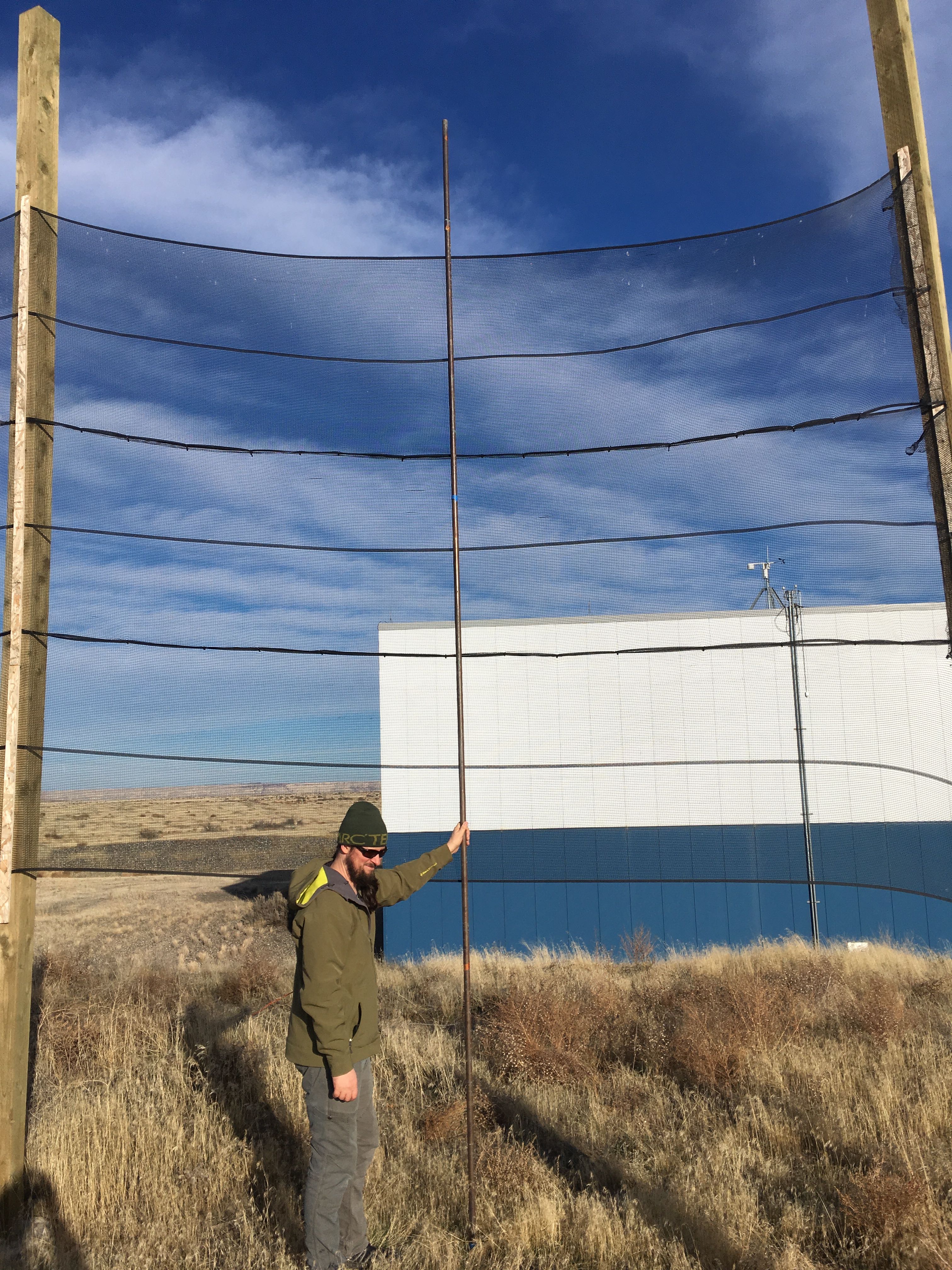
I assume the black black hat thing is the cone that collects the rain. The toggle thing is the rain gauge. The heating resistor is there to melt the snow.
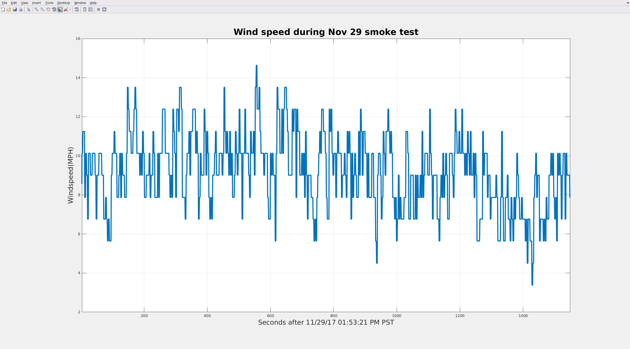
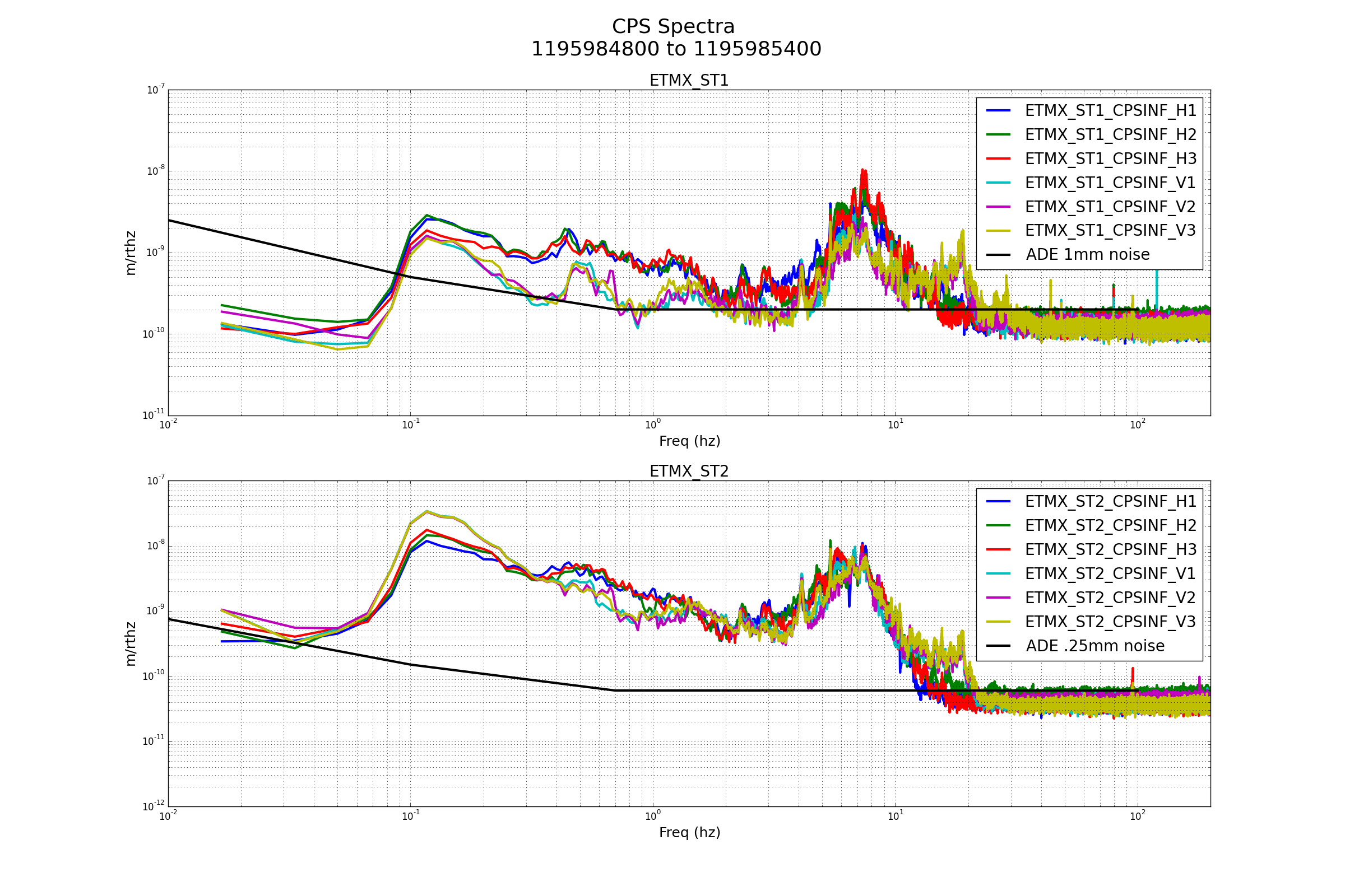
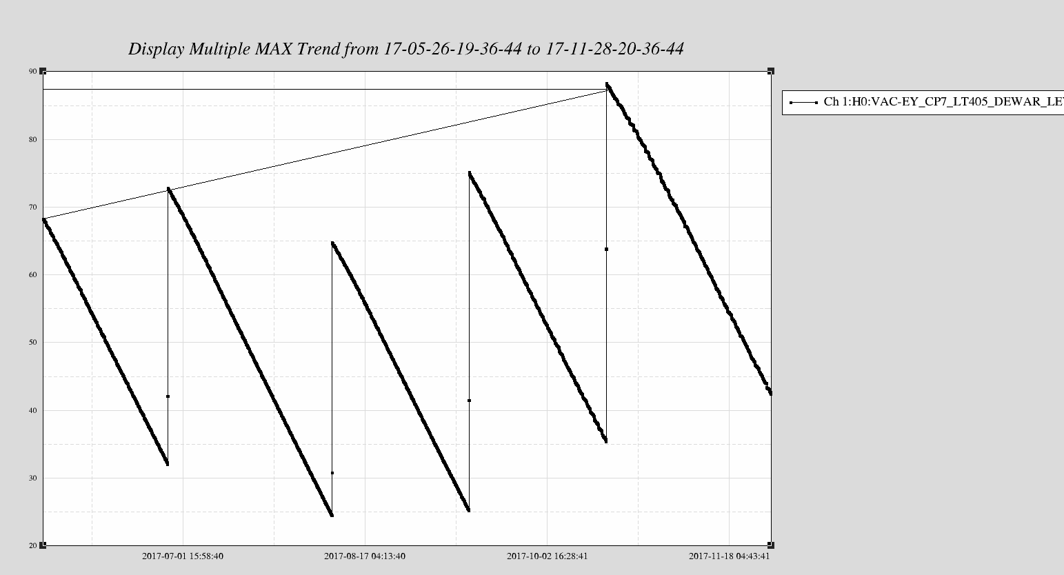
Went back and checked the EY anemometer this afternoon. Looks like the direction indicator for that one is not working correctly. At 3:39 pm I held the direction indicator so that it should read wind from the +X direction (180 according to Robert's site standard, see alog 28456 ). I held it there for about a minute, then pointed it so that it appeared to be a wind from the -Y direction, and should read 270. Held again for about a minute, then pointed back to +x (which is about where I found it, and where the wind is actually coming from). In the attached plot below, you can see that it isn't reading correctly, and also seems pretty noisy. (at about t=0, it should read 180, not 240, and around t=60, it should move up and read about 270, not 340)
Anyway, the EY anemometer direction is not to be trusted until Richard has a chance to take a look.