FRS9496
Jeff K, Richard, Dave:
At 07:30 PST Thursday 23rd November (Thanksgiving Day) PR3 rang up over two minutes. The T3 top OSEM shadow sensor RMS exceeded the 110mV threshold for 20 minutes continually, which caused the IOP Software Watchdog (SWWD) to DACKILL the h1sush2a DACs, at which time the oscillation stopped. The h1sush2a system remained in this state for the rest of the holiday weekend until the SWWD was reset this morning. Within an hour the ring-up occurred again. This cycle has repeated itself several times today. Investigation is continuing and an FRS has been opened.
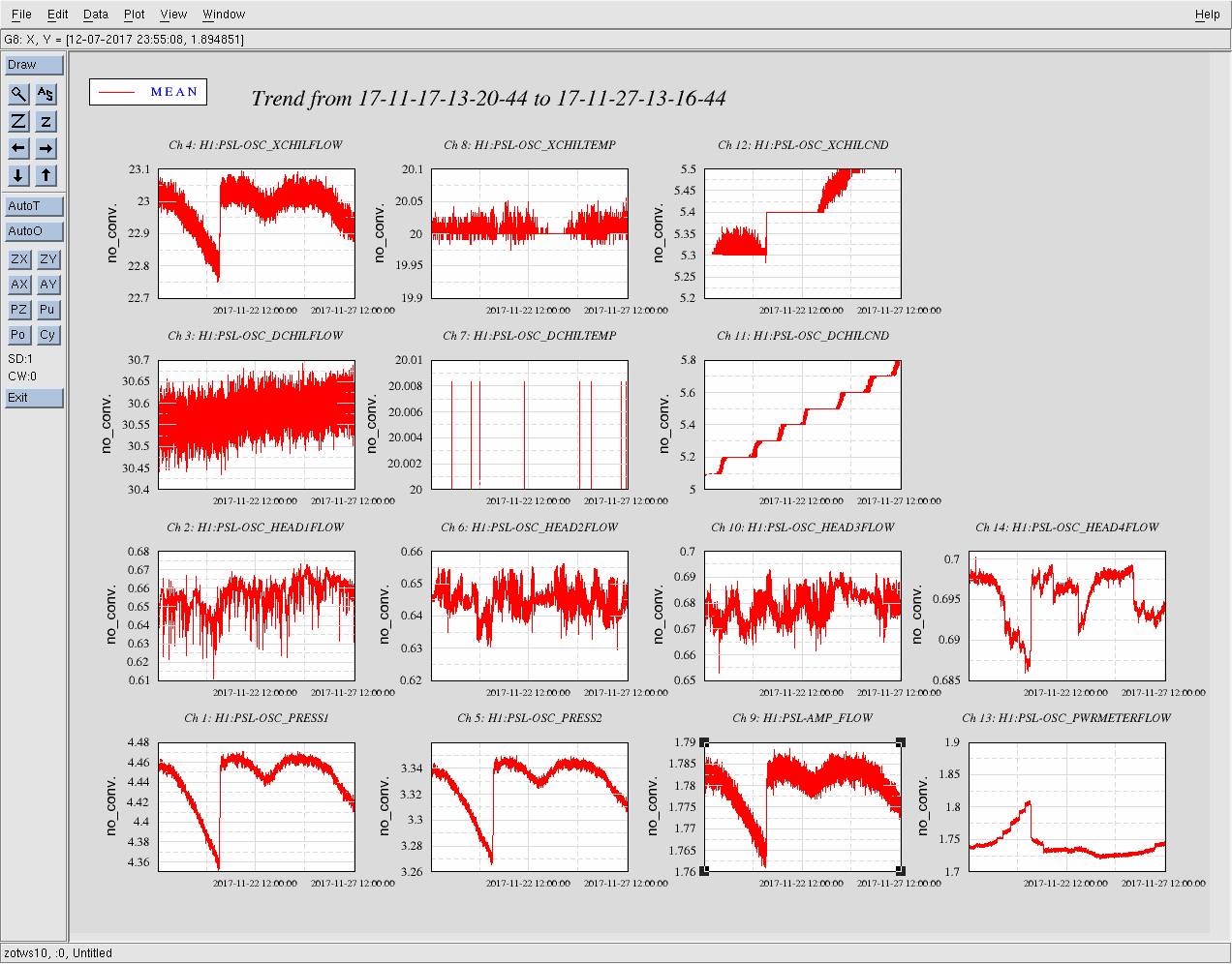
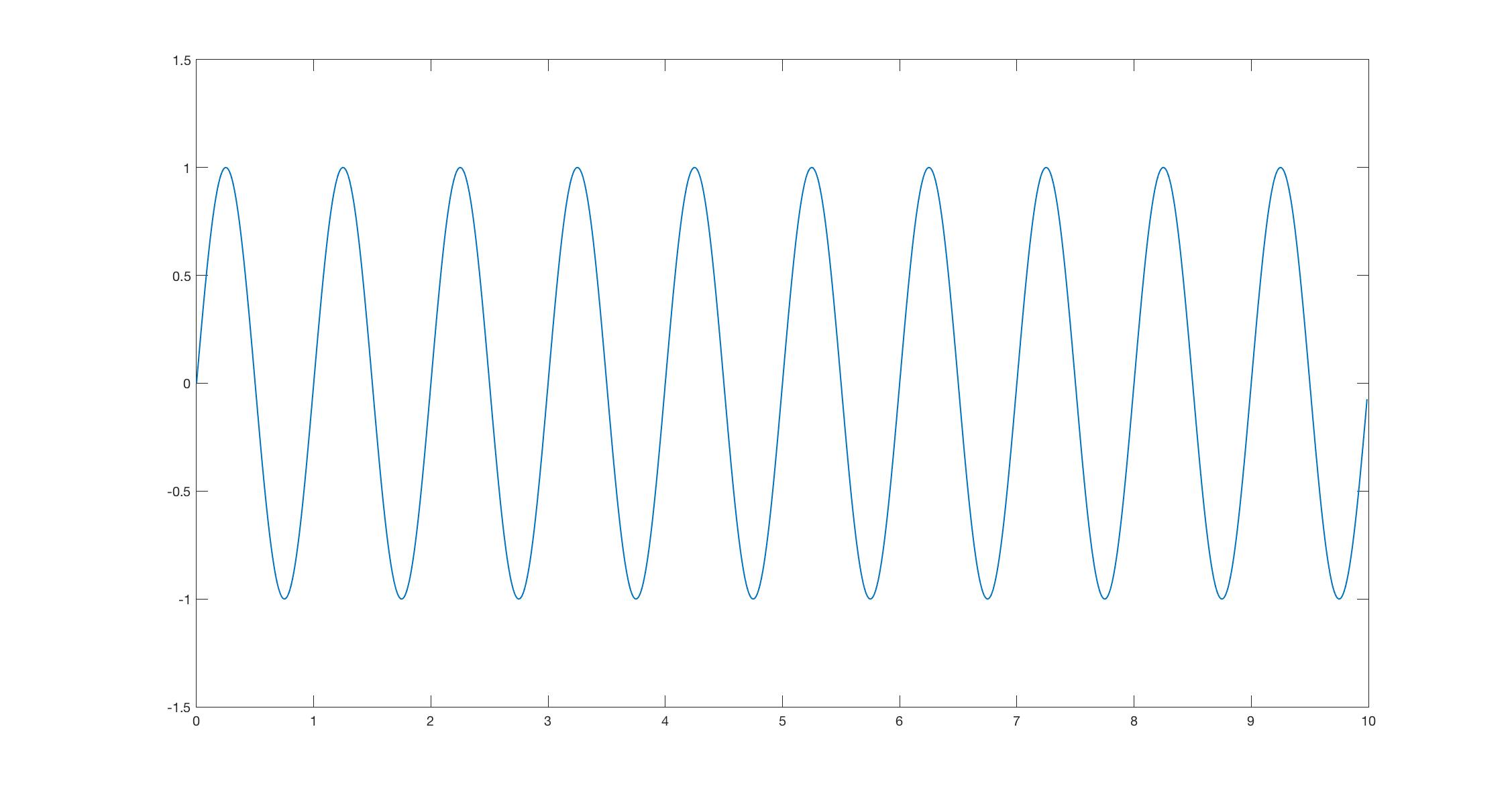
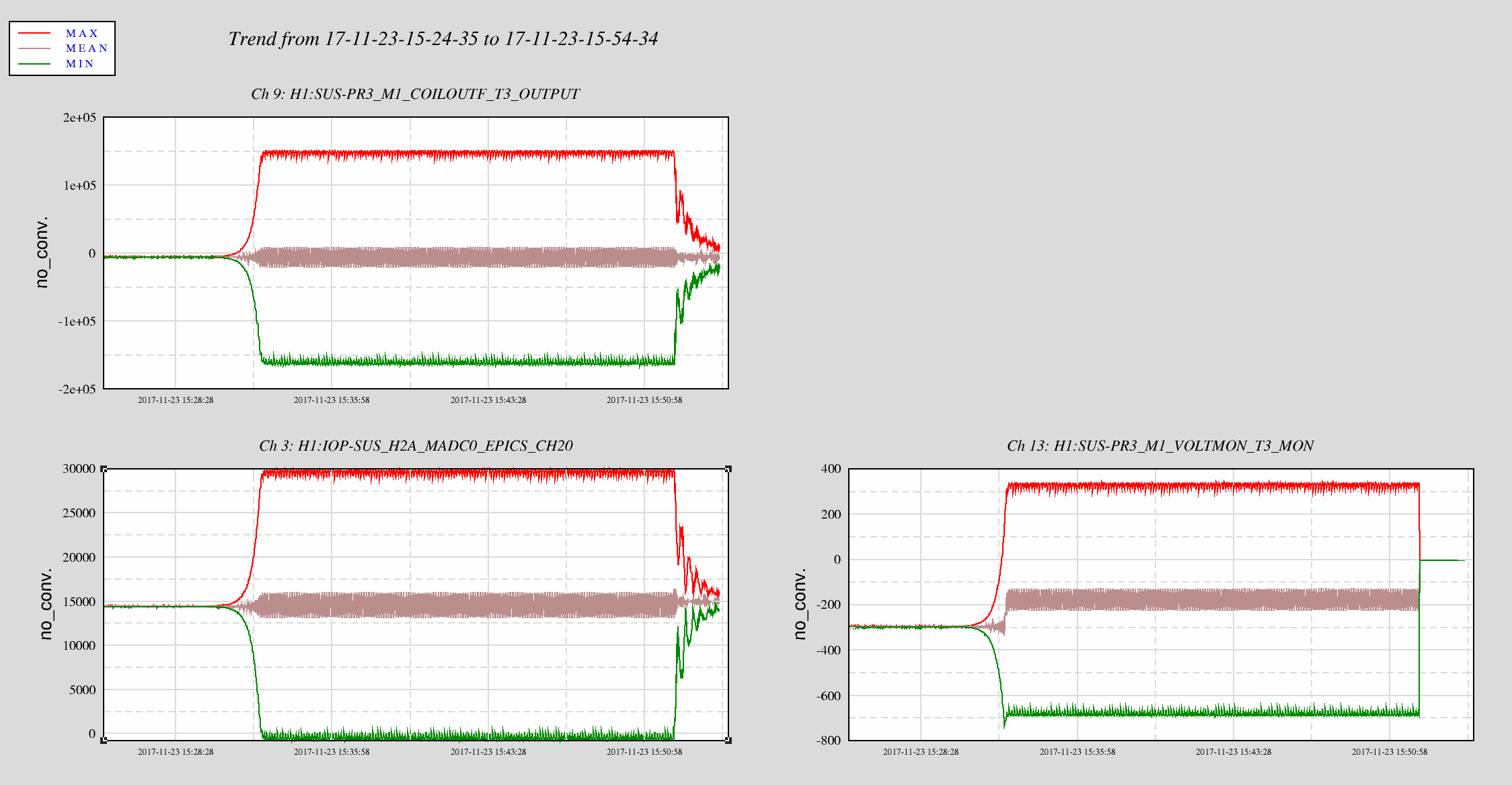
Attached plot shows a 30 minute second trend plot of the Thursday morning event. Data shown is: T3's shadow sensor ADC channel (Ch 3), the h1suspr3 T3 DAC drive (Ch 9) and the h1susauxh2 M1 T3 Voltmon. As can be seen, the OSEM shadow sensor and the model drive ring up in Unisom, driving the coil driver. After the SWWD trips the DACs at the 20 minute mark, the coil driver is quickly zeroed, which causes a bumpy ring-down of the shadow sensor (which the model's output mimics).
Open FRS Ticket 9497.
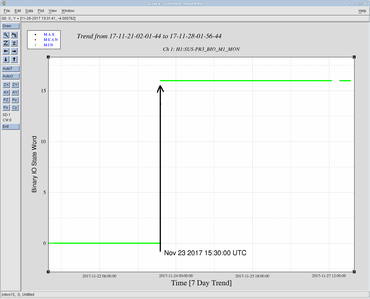
PR3 Damping goes unstable because the Top Mass (M1) T3 binary IO switch for its analog low pass is stuck with the filter ON, implying the relay has became suddenly de-energized at 15:30 UTC (07:30 PST) on 2017-11-23. It has remained stuck there since. Logic thread that got me there: (1) The L, T, and Y damping loops (composed of LF, RT, and SD sensor/actuators) work just fine. Turn any one of the V, R, or P loops on, and they eventually (over the course of 1 to 2 minutes) ring up and cause the software watchdog to trip. (2) Had the binary IO screen open, just to show Siddhesh how they work. Noticed T3 was in the wrong state. (3) Toggling the state request (H1:SUS-PR3_BIO_M1_STATEREQ) from 1 (analog low pass OFF) to 2 (analog low pass ON), changes all the 6 OSEMs to be in the low-pass ON state. In this state, the digital compensation matches the analog configuration, so all is normal w.r.t. the damping loop plant. This is the configuration we ran in for the rest of the afternoon without problem. (4) Now, having a little time to think, I realize: when in state 1, the T3 OSEM's analog filtering is still stuck with its low pass ON, but the digital compensation compensates for the low pass OFF state. This changes the damping plant for *one* of the OSEMs, which is involved in all three, V, R, and P loops, and causes the loop to be unstable. Concluding theory as to what happened: The triple-top circuit diagram D0902747 (pg2, a zoom of the relevant portion of the circuit is attached for convenience) shows the energized (+5V to the relay, a binary, digital 1 sent through the BIO card) configuration, which is the low-pass OFF condition. When power is lost, the switch flipped to the de-energized (0V to the relay, a binary, digital 0 sent through the BIO card) configuration, which is the low-pass ON. This is what I think happened Thanksgiving morning: the relay (due to analog electronics failure) failed, switching the analog circuit to low-pass ON with the digital compensation still compensating for the low pass OFF condition, V, R, and P damping loops when unstable, rings up the suspension, eventually tripping the Software Watchdog. I'll update the FRS ticket and let the analog CDS team to put it on their "to-fix" list. However, because we can happily run in state 2, I don't suggest we take the time to fix it until we're done with IFO alignment, unless it can be fixed some morning quickly before the team gets started. For now, I've left PR3 in STATE 2, with the damping loops ON.
Title pretty much sums it up. Photos attached for your viewing pleasure.
Two DAQ issues happened over the past 24 hours:
At 10:31 Sunday 26 Nov PST, the new E18 RAID on h1ldasgw0 became full. I thought I had more time to start the wiper code and was refactoring it. I manually cleared some space and will run the old wiper for now.
At 05:20 the DAQ data concentrator (h1dc0) crashed. It had been running for 208 days 18 hours, and crashed because of the 208.5 days issue the old 2.6.35 kernels have. We plan on upgrading to a modern kernel before the next 208.5 days expire. The DAQ acquired no data between 05:20 and 10:11 because of this issue.
Everything looks nominally ok. The humidity spikes are curiously sharp on the 24th.
OFI was realigned by Gerardo. Irises on HAM6 were put in place by TJ.
We installed a temporary HWP on OFI.
The beam was first centered on the steering mirror on OFI closer to ZM2 by using the other steering mirror on OFI. The centering accuracy is not good but it's not that important.
Then the beam was centered on ZM2. Centering accuracy I would say is a mm or so.
We rotated ZM2 so the beam is centered on the HAM6 iris closer to VOPO (i.e. more important one) for YAW. Fortunately the PIT was already about right, we didn't have to rebalance ZM2. All PIT fine adjustment was done using one of the steering mirrors on OFI.
Only after the beam was centered on the HAM6 iris closer to VOPO, we moved the second HAM6 iris in place and centered the iris without touching the beam.
The beam dump to catch the septum window reflection was roughly adjusted by eyeballing. Unfortunately it was impossible to see the AR reflection using IR viewer and a card, so instead I looked at the reflection of the ZM2 mirror outline on the septum window while positioning my eye on the line connecting the IR beam position on the septum and the apex of the V of the beam dump. The power coming to sqz path is like 300uW as of now, AR reflection should be much smaller than uW. Maybe we can increase the power to 10W (a factor of 40 increase) and see the beam.
Sheila and Jenne measured the power of the beam in the main sqz path using a power meter.
| On OFI between M1 and M2 steering mirror | 286 uW |
| Before 1st iris (closer to HAM5) on HAM6 | 288 uW |
| After 2nd iris (closer to VOPO) on HAM6 | 276 uW |
ZM2 and beam dump dog clamps are not super tight as I wasn't able to find the right tools. They need to be tightened and after that we need to confirm that the beam still comes through both of the irises.
Pictures to show the positions of ZM2, beam dump and two irises will be posted later.
Beam is centered on the input and output irises, I stopped at that point to allow Sheila and Keita to continue with the squeezer path.
Cage still needs some dog clamps, currently it has 3 holding it in place, input baffle needs to be replaced, AOSEMS need to be installed and damping needs to be revisited, table had to go up to center the beam on the apertures, thus changing the damping behavior.
Note about the output baffle, the beam is close to the -X side of the aperture. I will post a photo as one comes available.
TITLE: 11/22 Day Shift: 16:00-00:00 UTC (08:00-16:00 PST), all times posted in UTC
STATE of H1: Planned Engineering
INCOMING OPERATOR: None
SHIFT SUMMARY: Sheila, Nutsinee, and Terry still out in the SQZ Bay. Gerardo still tweaking OFI.
LOG:
I'm done tweaking the OFI Alignment for the day.
G. Moreno, T. Sadecki
The accelerometer and mount were installed on the HAM6 septum viewport. See attached photos for the serial number of the installed accelerometer. The accelerometer was plugged into the plug labeled 'B' on the octopus cable (interestingly, there was no plug labeled 'A', just 'B' though 'I'). The DB25 end of the octopus cable was NOT connected to the feedthru since other accelerometers are to be installed on the table at a later date, requiring that SEI lace the cable down the ISI.
In the last photo (DSCN0142), one can see (although not that clearly) that the hex head of the accelerometer mounting screw has the "curly shavings" from the hex head stamping process still intact. I recall these being a subject of concern during aLIGO install, so wanted to bring it up. This accelerometer is in the segregated HAM6 volume and has presumably passed an RGA scan, so perhaps there is no issue here.
FAMIS 6550
Added 200mL to the crystal chiller.
FAMIS 6925
During vent CPS check.
I wanted to get a quick summary of events on this spacer, but if I missed something or have something wrong please let me know.
On Friday, Keita and Sheila were aligning HAM5 and noticed that the beam height was odd going to ZM2. Jeff Kissel was consulted and he looked up drawings and found a possible discrepancy in the beam height. Some emails were exchanged with Lee McCuller and Koji, and in the mean time Keita, Sheila, Gerardo, and I talked to Lisa and Calum on TeamSpeak. Turns out that the spacer that sits under the ZM2 tip tilt (D1600005) was 0.76" too tall. Sheila and I measured in chamber and confirmed this (alog39477). This height difference comes from the difference in beam height on HAM5 between L1 & H1. Our two options:
a) Remove 0.76" from the spacer height and then clean, rebake, and reinstall.
- There was not enough material to remove from the bottom, and the top would need some holes drilled and tapped, then vent holes drilled on the sides. Modifying the top would create a higher contamination risk but seemed like easiest way to modify this. To speed up the process, we would need an approval on a waiver to allow a truncated version of cleaning and baking.
b) Deal with the height difference and try to move on with alignment.
- This was the ugly option because after we align the beam to ZM2, we are going to shoot it into HAM6 and through two iris's that will remain until the VIP is installed. The irises are nominally 4" off the HAM6 table, but with the ZM2 up 0.76" they would need to be raised up slightly. Finding correctly sized posts and making adjustments would be a pain. The other issue with this option is there was potential for loss due to the polarization change in the changing height. Keita did the matlab math (alog39478) and it turns out that it wouldn't be an issue, but the ugly alignment doesn't go away.
It was decided to chop the top (option a) and on Monday I pulled out the spacer, handed it off to Tyler to machine, and then he gave it to Chris for a clean and 12hr air bake. Yesterday, I reinstalled the spacer and aligned ZM2 to the coordinate drawing. Keita, Sheila, and I aligned the beam from the OFI to ZM2 in pitch and will do more with yaw either today or Monday after the holiday. Pictures attached to show height difference. For reference the spacer under the beam dump is what the TT spacer used to be.
Aside: the beam dump also sits on a spacer that is 0.76" too tall. This was an easy fix of just getting a slightly smaller post, so it wasn't the main character of this story.
B. Weaver, T. Sadecki
While we were investigating alignments of baffles, etc. while in HAM 4, we steered SRM such that the reflected beam went back to SR2. Screenshot of the new SRM slider values attached as a comment.
The dog clamps securing SR2 to HAM4 have been torqued to 8.5 ft/lbs (as close to 100 in/lbs (E1100411) as our torque wrench would allow) except for those on the north side of the structure. The heads of the screws for the dog clamps on the north side are so close to the structure that the head of the torque wrench would not fit. I attempted to duplicate the torque on these dog clamps by testing the already torqued dog clamps on the other sides of the structure and doing my best to replicate the force required to produce the torque using a normal flex handle socket wrench. Upcoming B&K measurements of this structure will tell if I did well.
Following on from Keita's alog from yesterday, we spent all day attempting to convince ourselves that the SR chain of optics are hanging symmetrically within their structures, using little to no tooling. Holding rulers up to various optics and structures, and painstakingly logging measurements, I could not find any reason to believe that the beam centering we've done between the center of SR2 and SRM is out by more than ~2mm. The PSL beam line that we have set between the center of SR2 and SRM looks good to carry on. Indeed, this may mean that the baffles do not look symmetric on the structures, but at least the beam path appears correct. We'll revisit baffle positions an drawings tomorrow.
Meanwhile, since I was wandering the tube between HAM4 and HAM5, I took a look at the beam centering going through the newly built SR2 scraper baffle D1003300. At first I was thrown off by the fact that the beam seemed to go through the baffle off center even though the baffle was installed using a template which I would have thought set it pretty close (within mm's). A lunch break consult with Keita and Calum pointed out that the beam I was looking at was only the SR3-to-SR2 beam which straddles the centerline of the baffle ellipse hole with the SR2-to-SRM beam which is hard to spot when viewing the SR3-to-SR2 beam with an IR card. A quick calculation, and a SW confirmation told us the 2 beams should be separated by 20mm and should straddle the centerline. Now how to find the center of the hole while standing in the dark with a viewer card and not occulting the beam with your body... I gave up trying to measure in-situ and instead opted for some pictures to scale.
Attached is the PDF scaled pic I used - I'm not spending any more time screwing around with the oddities of why the font is miniscule - what I did was:
- Scale the aperture in the picture to the 161mm dimension I read off the drawing D1003301 (for what ever reason Adobe makes starts the scale at a huge setting like some 40 inches or so)
- Using the new scaler, measure to the beam center shown in the picture
- 161mm /2 = 80.5mm is where the center of the aperture should be, so the beam center should be left of that by 10mm (half of the 20mm), 90mm.
- The beam is at 87.4mm. Of course it's hard to estimate the beam center since the beam is ~20-30mm in diameter, fuzzy, and moves a bit. I'd estimate the error of my ability to measure this centering to better than 5mm... Feel free to redo.
Seriously, please let that be close enough.
I did however, take a picture of what can be seen from the plane of the MCTube Eyeball baffle closest to HAM4 on the beam path (see below). Not sure I was able to place the camera on the beam line very well... I can confirm that everything shown in the left lobe cutout of the baffle is in dead all HWS silver mirror reflections (and no metal from mounts). It's hard to tell if there is a sliver of the right side of the SR2 optic still in the right portion of the right aperture lobe. Maybe it's the angle of my camera view. Dunno.
A consult with Calum who agreed that this alignment is good.
I have added new features to the element lal_resample used in the gstlal calibration pipeline so that it can perform upsampling for the actuation equal in quality to the old gstreamer (version 1.4.5) resampler. The upgrade to gsteramer-1.10.4 on the clusters introduced a ~2% systematic error in the C01 frames from ~50 Hz to ~1 kHz during the month of August. See, e.g., https://ldas-jobs.ligo.caltech.edu/~alexander.urban/O2/calibration/C00_vs_C01/H1/day/20170802/ The change made was the addition of a sinc table filter in the upsampling routine. Several tests were done, and plots are attached: The first two plots show the filter's response to a series of impulses separated by 4 seconds. This input data was upsampled from 128 Hz to 1024 Hz. The first of these plots shows 30 seconds of data, and the second is a close-up on a single impulse. The 3rd plot is a 10-second sinusoid upsampled from 8192 Hz to 16384 Hz. The 4th plot is a 30-second stream of ones upsampled from 128 Hz to 1024 Hz. The apparent thickness of the line indicates the amount of digital error, of order ~10^-8. The 5th and 7th plots are ASD comparisons between the output produced by the calibration pipeline using this new resampler and the C00 frames from August. The 6th and 8th plots are ASD comparisons between the output produced by the calibration pipeline using this new resampler and output pruduced with no resampling at all (i.e., all actuation was filtered at 16384 Hz). I suspect the wiggle above 1 kHz is due to a ~2% contribution from the actuation that is lost in downsampling to 2 kHz for the filtering. For information on filters to be used for C02 production, see https://alog.ligo-wa.caltech.edu/aLOG/index.php?callRep=39419 https://alog.ligo-la.caltech.edu/aLOG/index.php?callRep=36707
[Greg Mendell, Maddie Wade, Aaron Viets] Greg's tests revealed problems with the new gstlal-calibration code that were not present in the old versions, producing error messages like: *** Error in 'python': munmap_chunk(): invalid pointer: 0x00002babb1345780 *** ======= Backtrace: ========= /lib64/libc.so.6(+0x7ab54)[0x2ba8010eab54] ... ... I've found and fixed two bugs in the new resampler: 1) In certain places, a pointer to the next output buffer being produced was being incremented (but not dereferenced) beyond the end of the allocated memory of that buffer. 2) There was a particular corner-case where a pointer to where input data from previous buffers was being temporarily stored was being shifted to an incorrect location. After the fix, I ran the same tests, and they produced identical results. The only difference was that the jobs I found that produced errors no longer produced those errors.