david.barker@LIGO.ORG - posted 10:36, Thursday 17 July 2025 (85818)
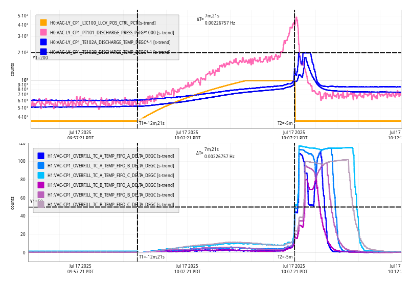
Thu CP1 Fill
Thu Jul 17 10:07:21 2025 INFO: Fill completed in 7min 17secs
Images attached to this report
Thu Jul 17 10:07:21 2025 INFO: Fill completed in 7min 17secs
Matt, Sheila, Camilla,
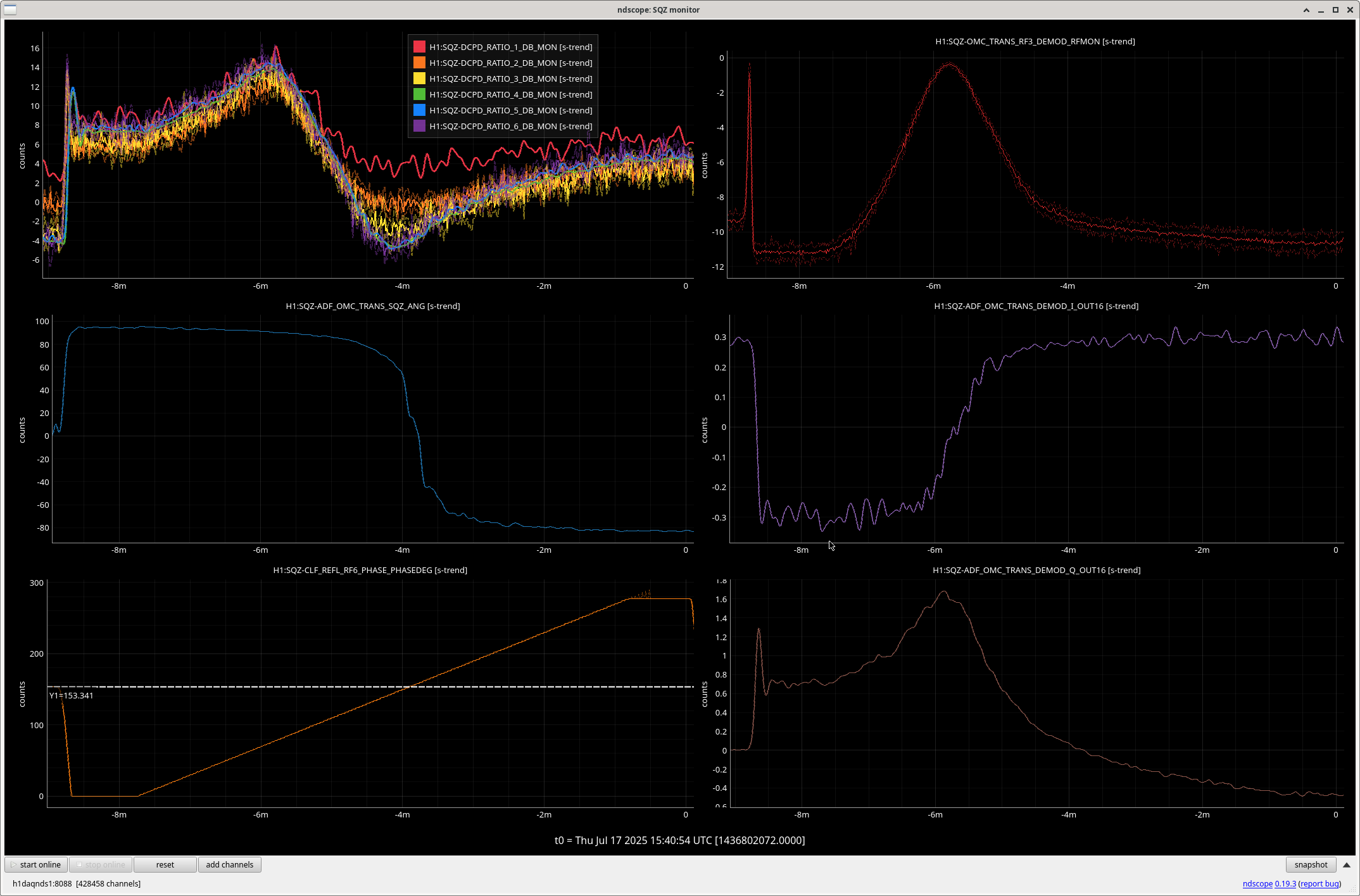
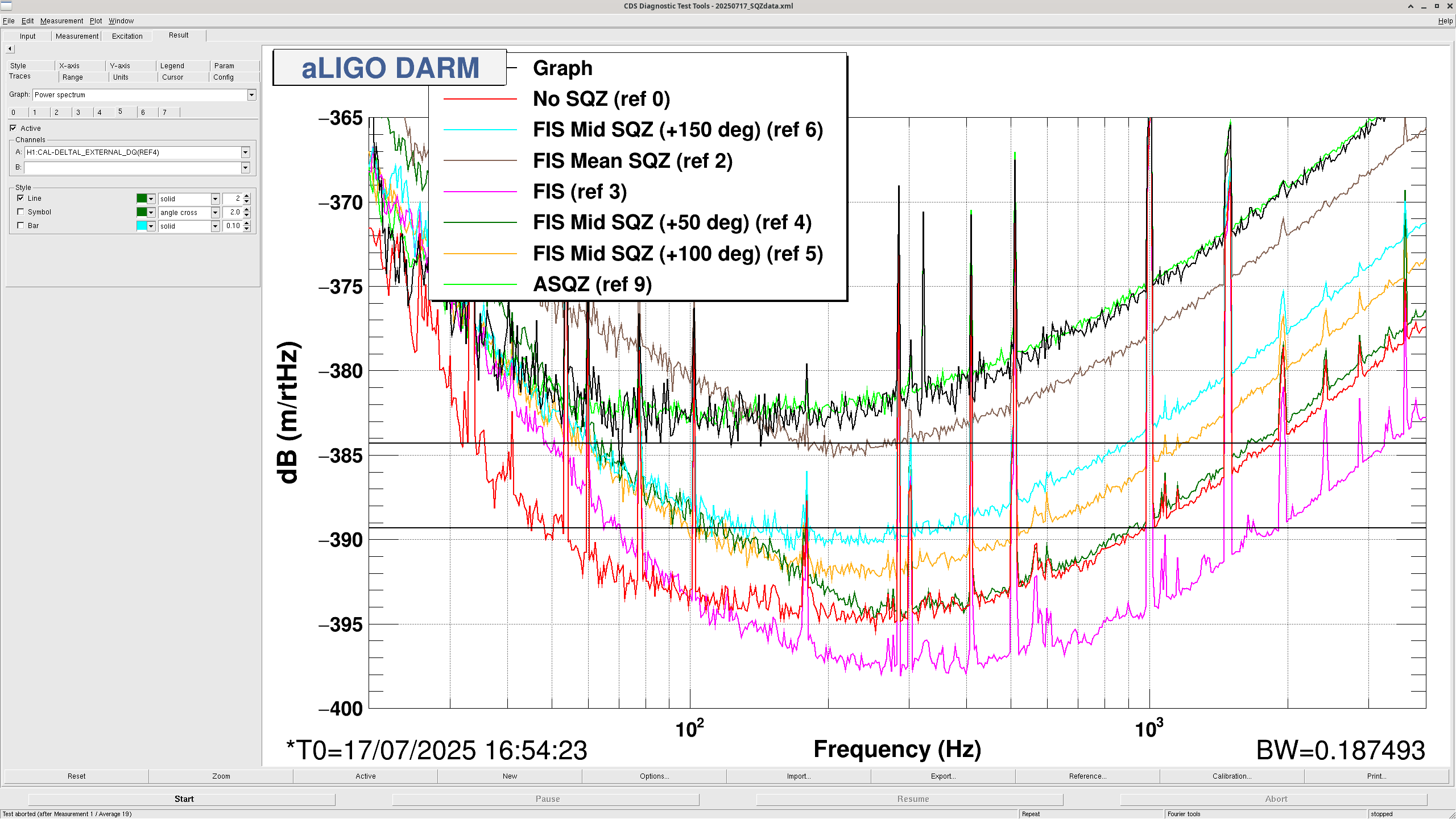
/ligo/home/matthewrichard.todd/Templates/sqz/20250717_SQZdata.xml and screenshot attached.Before we started we scanned the SQZ angle from 0 to 280deg using 'ezcastep H1:SQZ-CLF_REFL_RF6_PHASE_PHASEDEG -s '3' '+2,150'' to set it later for ADF plot attached, then we ran SCAN_ALIGNMENT_FDS, checked NLG, adjusted OPO temp. Starting angle at 141deg, SQZ_ANG_ADJUST changed it to 148deg.
| Type | Time (UTC) | Angle | DTT Ref | Notes |
| FDS | 15:51:00 - 15:54:00 | (-)148.4 | ref 1 | FDS after scan alignment and sqz ang |
| No SQZ | 15:54:30 - 16:02:00 | N/A | ref 0 | |
| FIS Mean SQZ (no ADF) | 16:04:00 - 16:07:00 | N/A | ref 2 | |
| FIS | 16:08:00 - 16:11:00 | (-) 148 | ref 3 | |
| FIS Mid + SQZ (+50deg) | 16:12:00 - 16:15:00 | (-) 198 | ref 4 | |
| FIS Mid + SQZ (+100deg) | 16:15:30 - 16:18:30 | (-)248 | ref 5 | |
| FIS Mid + SQZ (+150deg) | 16:24:00 - 16:27:00 | (+)120 | ref 6 | Had to change sign here, think we are going the correct direction again. |
| FIS Mid + SQZ (+200deg) | 16:27:30 - 16:30:30 | (+)170 | ref 7 | |
| FIS Mid + SQZ (+250deg) | 16:31:00 - 16:34:00 | (+)220 | ref 8 | |
| ASQZ | 16:36:30 - 16:39:20 | (+)245 | ref 9 | Note we flipped sign in last 10sec of data so only have 2m50s here |
|
FIS Mid - SQZ (-50deg) |
16:40:30 - 16:43:30 | (-)98 | ref 10 | |
| 16:44:00 - 16:47:00 | (-)48 | ref 11 | Note that we'd already gone over ASQZ here | |
| FIS Mid - SQZ (-20deg) | 16:48:00 - 16:51:00 | (-)128 | ref 12 | |
| FIS Mid - SQZ (-75deg) | 16:51:30 - 16:54:30 | (-)73 | ref 13 | |
| ASQZ | 16:55:30 - 16:58:30 | (-)65 | ref 14 | ASQZ again at different SQZ angle (looks the same) |
| FIS Mid - SQZ (-35deg) | 16:59:00 - 17:02:00 | (-)113 | ref15 | |
| FDS Mid SQZ + | 17:06:30 - 17:09:30 | (-)203 | ref16 | |
| FDS Mid SQZ - | 17:12:00 - 17:15:00 | (-)120 | ref17 |
| OPO Setpoint | Amplified Max | Amplified Min | UnAmp | Dark | NLG | OPO Gain | Note |
| 80uW | 0.0948 | 0.0023 | 0.00705 | -2.24e-5 | 13.4 | -8 | With changing OPO temp |
I took 5 minutes of no-sqz data at 524 kHz and saved the outputs as .gwf files in /ligo/home/elenna.capote/OMC_DCPD/251707-103227_xcorr_data
Just some quick directions on how to run a script to get the full 524 kHz DCPD data, and then save it in a useful file format.
The script to save this is in /ligo/home/elenna.capote/OMC_DCPD/H1OMCDPCD_HF.py
Right now it is set to collect data from these two channels (line 62 of the code):
channels = ["H1:OMC-DCPD_A0_OUT", "H1:OMC-DCPD_B0_OUT"]
The amount of time to collect data is set on line 66:
duration = 600 # seconds
To run the code:
> conda activate labutils
> python H1OMCDPCD_HF.py
The files will be saved in /ligo/home/elenna.capote/OMC_DCPD in a new folder labeled with a datetime and "xcorr_data" since I have traditionally used this script to collect data for cross correlation measurements. However, you can change the label on line 71, label="xcorr_data"
The output is a set of 1 second HDF5 frames for each second of data collection (so 600 seconds = 600 files). To put this data into a single .gwf format of the full data length, which can easily be read in with GWPY, use the combine.py script. Copy combine.py into the new directory with the frames and run it. The code generates a file for each OMC DCPD channel at the full rate, and at a decimated 64 kHz rate.
This is a bit odd the way it is set up, but the way this works ensures that even if you have to quit the script early, you don't lose all the data, since it saves each file by the second.
We were locked for over 6.5 hours when the measurements were started.
Simulines start:
PDT: 2025-07-17 08:07:30.859380 PDT
UTC: 2025-07-17 15:07:30.859380 UTC
GPS: 1436800068.859380
Simulines end:
PDT: 2025-07-17 08:30:47.210989 PDT
UTC: 2025-07-17 15:30:47.210989 UTC
GPS: 1436801465.210989
Files:
2025-07-17 15:30:47,050 | INFO | File written out to: /ligo/groups/cal/H1/measurements/DARMOLG_
SS/DARMOLG_SS_20250717T150731Z.hdf5
2025-07-17 15:30:47,058 | INFO | File written out to: /ligo/groups/cal/H1/measurements/PCALY2DA
RM_SS/PCALY2DARM_SS_20250717T150731Z.hdf5
2025-07-17 15:30:47,062 | INFO | File written out to: /ligo/groups/cal/H1/measurements/SUSETMX_
L1_SS/SUSETMX_L1_SS_20250717T150731Z.hdf5
2025-07-17 15:30:47,067 | INFO | File written out to: /ligo/groups/cal/H1/measurements/SUSETMX_
L2_SS/SUSETMX_L2_SS_20250717T150731Z.hdf5
2025-07-17 15:30:47,073 | INFO | File written out to: /ligo/groups/cal/H1/measurements/SUSETMX_
L3_SS/SUSETMX_L3_SS_20250717T150731Z.hdf5
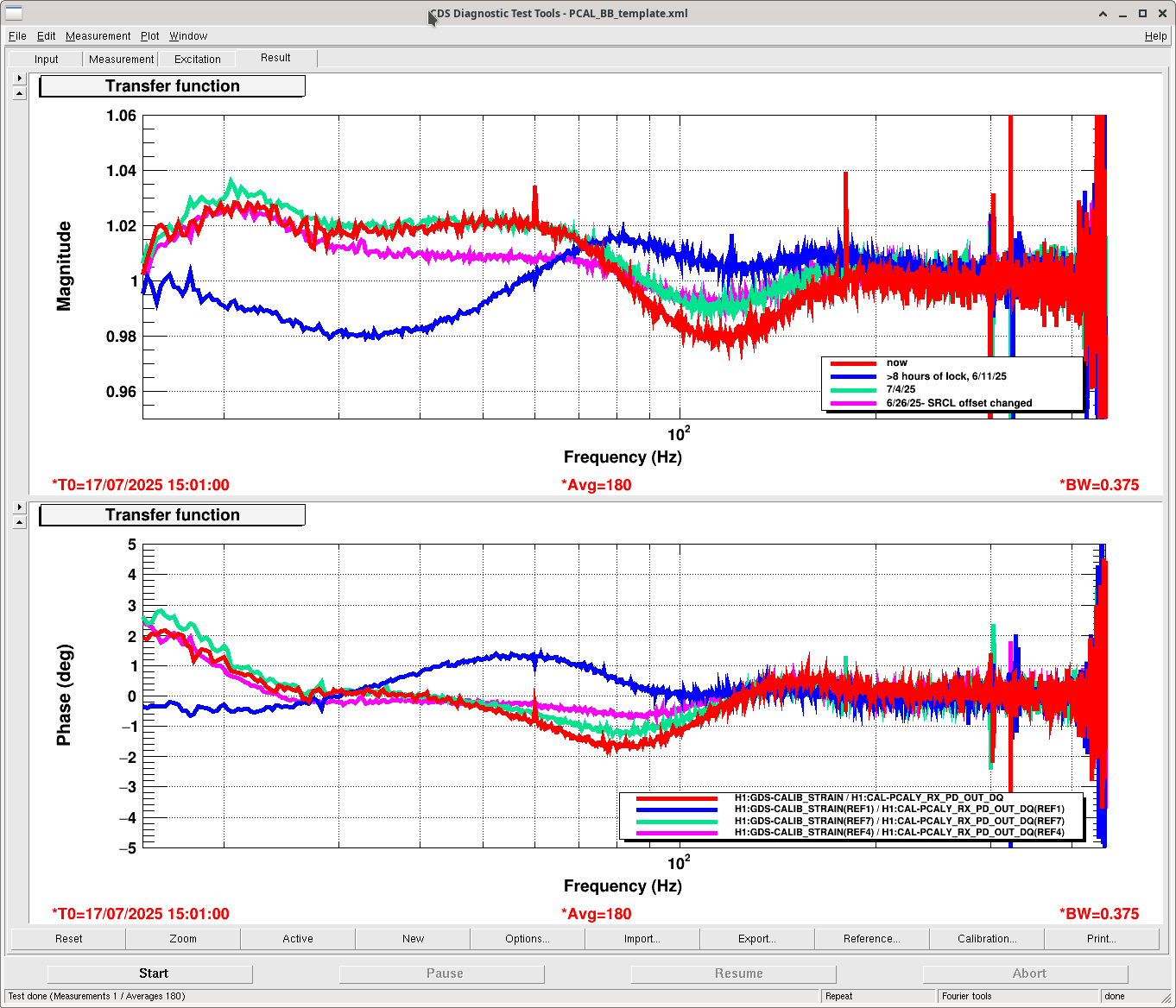
Here is today's broadband compared with some recent calibration measurements.
TITLE: 07/17 Day Shift: 1430-2330 UTC (0730-1630 PST), all times posted in UTC
STATE of H1: Observing at 145Mpc
OUTGOING OPERATOR: Ryan S
CURRENT ENVIRONMENT:
SEI_ENV state: CALM
Wind: 6mph Gusts, 3mph 3min avg
Primary useism: 0.02 μm/s
Secondary useism: 0.18 μm/s
QUICK SUMMARY: We've been locked for 6.5 hours, range steady around 150Mpc. Looks like the earth has finally calmed down after the large earthquake and aftershocks in Alaska yesterday. Planned calibration and commissioning today (1500-1930UTC).
State of H1: Observing at 154Mpc
Following the power supply replacement at EX earlier tonight, Oli and I were able to recover H1 and run an initial alignment (only ETMX needed some adjustment). Lock acquisition afterwards went without issue and fully automatically and H1 began observing as of 08:16 UTC.
One thing that needed attention after rebooting the EX frontends is a restart of the ALS_XARM Guardian to reinitialize its awg connections; something we've encountered before after frontends are rebooted. I also restarted PEM_MAG_INJ and ESD_EXC_ETMX while I was at it, as I think these are the only nodes that need an awg connection to EX.
TITLE: 07/16 Eve Shift: 2330-0500 UTC (1630-2200 PST), all times posted in UTC
STATE of H1: Corrective Maintenance
INCOMING OPERATOR: Ryan S
SHIFT SUMMARY: Ryan S is currently working to get the detector back up through running an initial alignment after Dave and Fil helped fix the power supply failure at EX (85805).
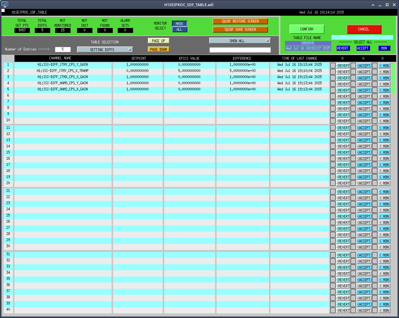
After getting back up after the earthquake, there were some sdf diffs relating to the Big Red Button:
- On ISIHAM2/3/4/5 saying that there were filter diffs for ISI-HAM{2,3,4,5}_GS13INF. I called Jim and he let me know that those were because of SPM diffs on each HAMs' ISI_HAM{2,3,4,5} guardian and that all I needed to do was INIT each of the guardians. I did that and they cleared.
- On SEIPROC - Jim fixed those somehow (sdf)
LOG:
23:00UTC Unlocked and waiting for the ground to calm down from the huge earthquake
00:31 Started trying to relock
- Ran an initial alignment
01:52 NOMINAL_LOW_NOISE
- Had SDF diffs from ISIHAM2/3/4/5 saying that there were filter diffs for ISI-HAM{2,3,4,5}_GS13INF. I called Jim and he let me know that those were because of SPM diffs on each HAMs' ISI_HAM{2,3,4,5} guardian and that all I needed to do was INIT each of the guardians. I did that and they cleared.
There were also a few sdf diffs on SEIPROC that Jim fixed somehow
02:16 Observing
03:49 GRB-Short E581446 - Observing
04:11 Lockloss due to power supply failure
- ETMX M0/R0 suspension WD tripped
- ETMX and TMSX OSEMs in FAULT
- ETMX HWWD tripped (I put SEI_ETMX in ISI_OFFLINE_HEPI_ON beforehand)
05:02 GRB-Short E581463 - not locked
06:39 Started trying to relock
| Start Time | System | Name | Location | Lazer_Haz | Task | Time End |
|---|---|---|---|---|---|---|
| 05:42 | EE | Fil | EX | n | Replacing power supply | 06:34 |
Lockloss at 2025-07-17 04:11 UTC due to a power issue with ETMX and TMSX. Currently in contact with Dave and Fil is on his way in.
ETMX M0 and R0 watchdogs tripped
ETMX and TMSX OSEMs are in FAULT
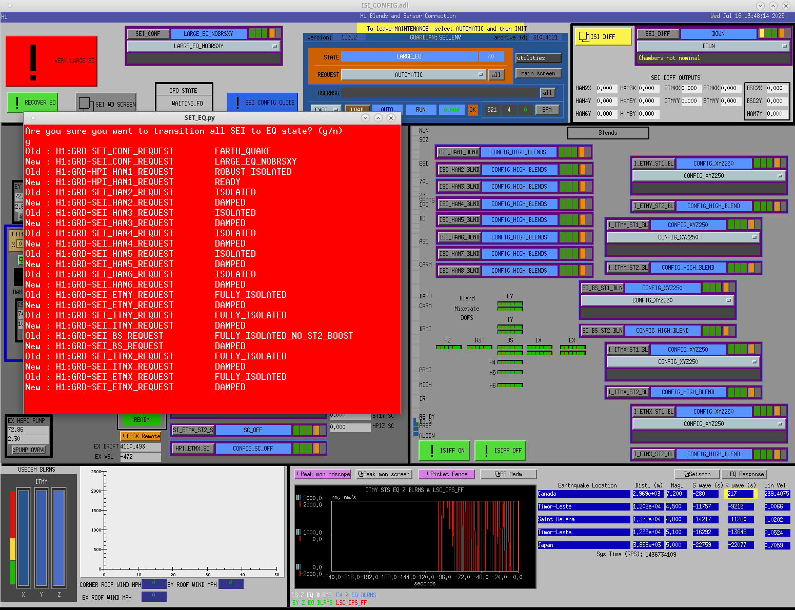
ETMX ESD off
ETMX HWWD notified that it would trip soon, so SEI_ETMX was preemptively put into ISI_OFFLINE_HEPI_ON to keep ISI from getting messed up when it trips
H1SUSETMX ADC channels zeroed out at 21:11:39. SWWDs did not trip because there is no RMS on the OSEM signals, but the HWWD completed its 20 minute countdown and powered down the three ISI coil drivers at 21:32. This indicates ETMX's top stage OSEMs have lost power.
I've opened WP12692 to cover Fil going to EX to investigate.
During the recovery the +24VDC power supply for the SUS IO Chassis was glitched which stopped all the h1susex and h1susauxex models. To recover I first did a straight forward reboot of h1susauxex (no Dolphin), it came back with no issues.
To reboot h1susex was more involved, remember that the EX Dolphin switch was damaged by the 06 April 2025 power outage and has no network control. The procedure to reboot h1susex I used was:
When h1susex came back, I verified all the IO Chassis cards were present (they were all there)
I unpaused the SEI and ISC IPC by writing a 0 to their IPC_PAUSE channels.
The HWWD came back in nominal state.
I reset the SUS SWWD DACKILLs and unbypassed the SEI SWWD.
DIAG_RESET to clear all the IPC errors (it did so) and clear DAQ CRCs (they cleared).
Handed systems over to control room (Oli and Ryan S).
From Fil:
-18VDC Power supply had failed and was replaced.
Power supply is in rack VDD-2, location U25-U28, right-hand supply, label [SUS-C1 C2]
old supply (removed) S1202024
new supply (installed) S1300288
Last night's HWWD sequence is shown below. Reminder that at +40mins the SUS part of the HWWD trips, which sets bit2 of the STAT. This opens internal relay switches, but since we don't route the SUS drives through the HWWD unit (too noisy) this has no effect on operations. The delay between 22:52 and 23:20 is because h1iopsusex was down between 23:01 and 23:20.
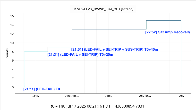
Fan motor seized on failed power supply.
Wed16Jul2025
LOC TIME HOSTNAME MODEL/REBOOT
23:15:13 h1susauxex h1iopsusauxex
23:15:26 h1susauxex h1susauxex
23:20:21 h1susex h1iopsusex
23:20:34 h1susex h1susetmx
23:20:47 h1susex h1sustmsx
23:21:00 h1susex h1susetmxpi
Based on noise budget injections that we have been running since the vent recovery, I put together a low frequency LSC and ASC sub-budget, and made a total budget.
The results show that the noise that limits DARM from 10-20 Hz is very well understood by LSC and ASC noise. Above 20 Hz, ASC noise drops quickly to be more than a factor of 10 below DARM. LSC noise first drops to a factor of 3 below DARM at 20 Hz and then closer to a factor of 5 by 40 Hz.
For the ASC subbudget, I focused on the "usual suspects", choosing to show the HARD loops as well as the MICH ASC. During vent recovery, both MICH ASC loops were put into a higher bandwidth state to counter various instabilities. I'd like to try to put them back in a lower noise control design, which may directly lower DARM noise to at least the level of DHARD Y in the ASC budget. This budget incorporates the slightly lower noise DHARD that I implemented yesterday. Since the vent, CHARD P noise has been the lowest it has been for O4 due to the improved isolation of the HAM1 chamber. Notably missing here is CSOFT P, which I haven't been able to measure yet, but tends to strongly couple to DARM from about 10-15 Hz. The other soft loops couple less, and are not very likely to have a significant effect on this result.
If we can achieve some reduction of the ASC noise, we will reach the LSC noise limit, which is limited by our ability to fit the feedforward well at low frequency.
This noise budget does not include DAC noise or OSEM noise, although we've previously shown those to be smaller than the LSC and ASC noise, especially above 20 Hz.
These budgets were made using excess power projections. The DARM trace and ambient noise levels were chosen from an observing time last night, and the coupling functions were measured recently in June.
TITLE: 07/16 Eve Shift: 2330-0500 UTC (1630-2200 PST), all times posted in UTC
STATE of H1: Earthquake
OUTGOING OPERATOR: RyanC
CURRENT ENVIRONMENT:
SEI_ENV state: EARTHQUAKE
Wind: 13mph Gusts, 5mph 3min avg
Primary useism: 0.52 μm/s
Secondary useism: 0.45 μm/s
QUICK SUMMARY:
We are currently in DOWN still waiting out the huge earthquake from Alaska that came through a bit ago (85799). Ground motion is still pretty elevated, so it mgiht be another couple of hours at least until we can start trying to recover the ifo
02:16 UTC Back to Observing
TITLE: 07/16 Day Shift: 1430-2330 UTC (0730-1630 PST), all times posted in UTC
STATE of H1: Earthquake
INCOMING OPERATOR: Oli
SHIFT SUMMARY: We stayed lock for most of the shift, a large earthquake struck soon after losing lock. We're still ringing down as of 23:30UTC.
LOG:
| Start Time | System | Name | Location | Lazer_Haz | Task | Time End |
|---|---|---|---|---|---|---|
| 14:39 | FIT | Camilla, IPA members | Yarm | N | Walk/Jog started at 14:00 | 15:22 |
| 16:41 | FAC | Kim | Optics lab | N | Swiftin' | 16:59 |
| 21:05 | VAC | Travis, Gerardo | LVEA | Y | VAC work | 21:20 |
| 21:06 | SAF | LVEA IS LASER HAZARD | LVEA | Y | LVEA IS LASER HAZARD | 07:06 |
20:29 UTC Lockloss
Appears to be from an ETMX glitch
