The channels of the ASAIR LSC PDs were removed from the h1omc and h1lsc models. In the process a mistake with the OMC PZT readback channels was discovered. The DAQ channel list showed only 2 channels being hooked up, whereas in reality four channels are used. These 2 additional channels were intended for the CLF REFL RF6 readbacks. Issued ECR E1700426 to fix this. The LSC REFL and IMC CM board readbacks are now routed thru the ADC concentrator which inserts the CLF REFL channels into the two unused channels. This required a reconfiguration of the concentrator and a few reconnections in the ISC-C1 rack, as well as a change ot the h1sqz model.
By noon, all HEPI Actuators were valved into the fluid stream and the pressure is running at nominal level (70 psi differential) under PID control. The Reservoir Level switch has been set to trip with a drop in level of 1 to 3/16". After 2 1/2 hours running steady state, there is no loss in reservoir level and inspection of the entire LVEA shows no problems. I did not expect anything and if there were I'd expect a slow ooze rather than a flood.
I cleared out a buncha stuff on the SUS SDFs that were left over from BIO state switching, testing settings, and updated gains and offsets. The first 2 were reverted back to their nominal states, the later 2 were updated.
The two attached trend plots show the X & Y dofs of the ISI CPS for HAMs 2 & 3 for the past ~90 days.
Bottom line: I will reset the isolating position to the current free hanging position. Looking at the trends over the last few months while working on the IO, the locked positions for HAMs 2 & 3, X & Y have been ~40 to 50 um at worst and within a few um of the now free hanging positions. It seems this shift in X & Y would not be noticed by the beam path.
Detail:
| State | Free hanging um |
Locked position um |
||
| DOF | X | Y | X | Y |
| HAM2 | 15 | -66 | -20 to 0 | -55 to -35 |
| HAM3 | 10 | 2 | -5 to -1 | -2 to + 10 |
We'll revisit these numbers after pump down. Setting these servo to position to the free hanging position is an effort to make the isolating smoother and less likely to cause an isi trip. Additionally, when the platform does trip, the platform should move less making other systems (Sus) less likely to trip.
SDFs (safe and OBSERVE) updated and committed to svn:
hugh.radkins@opsws1:burtfiles 0$ svn st
M h1isiham3_OBSERVE.snap
M h1isiham2_safe.snap
M h1isiham3_safe.snap
M h1isiham2_OBSERVE.snap
hugh.radkins@opsws1:burtfiles 0$ svn commit -m "update cart bias targets"
Sending burtfiles/h1isiham2_OBSERVE.snap
Sending burtfiles/h1isiham2_safe.snap
Sending burtfiles/h1isiham3_OBSERVE.snap
Sending burtfiles/h1isiham3_safe.snap
Transmitting file data ....
Committed revision 16523.
hugh.radkins@opsws1:burtfiles 0$ pwd
/opt/rtcds/userapps/release/isi/h1/burtfiles
hugh.radkins@opsws1:burtfiles 0$
I restarted the h1lsc0 models at about 18:00 UTC. All of the non-IOP models showed a FE failure and DAQ failure. All of the corresponding models that do IPC with the h1lsc0 models are showing IPC errors (as expected). When I looked on the front end the models were loaded and the epics processes where running. I issued a /etc/stop_models.sh and /etc/start_models.sh.
I cleared the IPC errors on all front ends connected to the LSC by hitting the DIAG RESET on them. Now we are all GREEN.
I've attached some of the kernel logs (via dmesg).
For the weekly HAM/BSC CPS FAMIS task (#6929), received data errors. Consulted with Hugh and he mentioned this is probably related to nds, so will not perform this task and will CLOSE it.
These are the particle count trends in the LVEA for the past week. They are good. The spikes are mostly associated with vent closeout activity, and clear quickly. After the new year, Dave Barker and I will shutdown and remove the extra dust monitors from the LVEA and set up the monitors needed to support the vents of the end stations.
Mark D., Tyler G. and Bubba G. having tacked on both of HAM3's doors this afternoon has left us with only three chamber door openings with soft-covers on. As such, we had to dial back the purge air supply from its recent nominal value of 100% open to something much less so as to not blow these three covers off! Again, not yet having a flow meter in-line with the purge-air supply results in many theories etc.. but everything now seems typical of the historical behavior with the purge air. Also, the dew point is dropping as a result - two hours after HAM3's doors went on it has dropped down to -31C from a months long steady value of around -28C. BSC1's annulus pressure is still good and getting better (see discussion from yesterday). BSC3's annulus pressure, on the other hand, had seemed to have bottomed out at the pump cart (2.1 x 10⁻⁵ Torr) since yesterday. So, this evening, I closed the annulus isolation valve and noted that the pump cart pressure didn't respond. Having a leak on the pump side of the isolation valve "muddies the water" a little bit. We don't have the luxury of starting the ion pump and monitoring the current over a period of days - so, we will try and spray a little helium tomorrow so as to rule out an outer O-ring leak that might be getting "masked" my the pump-side leak. The fourth of 4 NEG pumps is finishing up a "cycle" of particulate mitigation in the lab and should make the deadline tomorrow to be available to get installed.
Sheila, Nutsinee, TJ
I've updated this entry with correct numbers, I made 2 basic errors the first time.
Last week we set up the Faraday isolator on the squeezer platform (VIP) and made transmission, isolation and backscatter measurements. We tried to optimize the angles of the polarizers and the half wave plate for transmission to reduce losses for the squeezing. Our results are 96% transmission, -20 dB of isolation, and less than -36dB of backscatter. As we assembled the Faraday, we tried to adjust each angle for transmission.
Details
We roughly followed the measurement procedure from Maggie's wiki, with minor differences. The set up is shown in the attachment (the beam path looks curved in the photo because of my poor photography). We used a chopper to measure transfer functions between two PDs, one at Pos A (monitor of laser power into set up on one side of 50/50 BS), and the other moving between Pos B (measurement of power onto VIP), Pos C (power transmitted through Faraday), and made two measurement at position D, first the return power from the Faraday with the HR retro reflecting the beam back through the Faraday to measure isolation and second with a razor blade beam dump in pos D to measure backscatter off the Faraday itself. Before the 50/50 beam splitter we added a f=1m lens to make sure the beam diameter stays well below the 5mm rotator aperture through the entire set up, and a PBS cube mounted to transmit vertically polarized light.
We found that the efficiency of each of the PDA100A's we used depended on the angle of the PD. We initially tried to set markers for the position of the reflection off the PDs so that we could reproduce the angle that we mounted the PDs at each time we moved them, but found that the two PDs have reflections at very different angles. We used small C clamps on the post to mark the height, and tried to use the knobs on the C clamps to keep the PD angles consistent from position to position. We cannot use the PDs face on because as Maggie found at LLO the scatter from position A to position D will cause measurement problems.
Measurements: We have made these measurements twice, first with the initial assembly of the Faraday, this afternoon I went in and adjusted the thin film polarizers but ended up with slightly worse transmission and isolation.
The ratio of a measurement of before and after the Faraday to the beamsplitter reflection (C/A)/(B/A) gives us the Faraday transmission with the PD efficiency and input power canceling out, we measured this with both PDs in each position. With the orginial tuning of the Faraday, with PD1 before and after the Faraday, we measured 96.9% transmission, with PD2 before and after the Faraday we measured 96.5% transmission. This afternoon with PD1 before and after the Faraday, we measured 96.4% transmission, with PD2 before and after the Faraday we measured 96.5% transmission
The ratio of the measurement with the PD after the Faraday to the return beam from the Faraday with the high reflector in place (D/A)/(C/A) is the transmission of the Faraday in reverse multiplied by the beamsplitter reflectivity. For the initail set up we measured 22.5 dB of isolation (with both PD placements), this afternoon after "tuning" I measured -20.5 moving PD1 in transmission of the Faraday, and -19dB with PD2 in transmission of the Faraday.
With the razor blade beam dump instead of the retro-reflector after the Faraday, we can estimate backscatter from the Faraday back towards the OPO. If this scatter is large, it can reduce the measured isolation. For this measurement I am using the power returning over the power incident on the PD, (D/A)/(B/A), and dividing our the beam splitter reflectivity, which gave -34 dB with both PDs for the original angle tuning. After changing the angles, the backscatter is too small to measure, so backscatter isn't a large impact on our isolation measurements.
Beam heights:
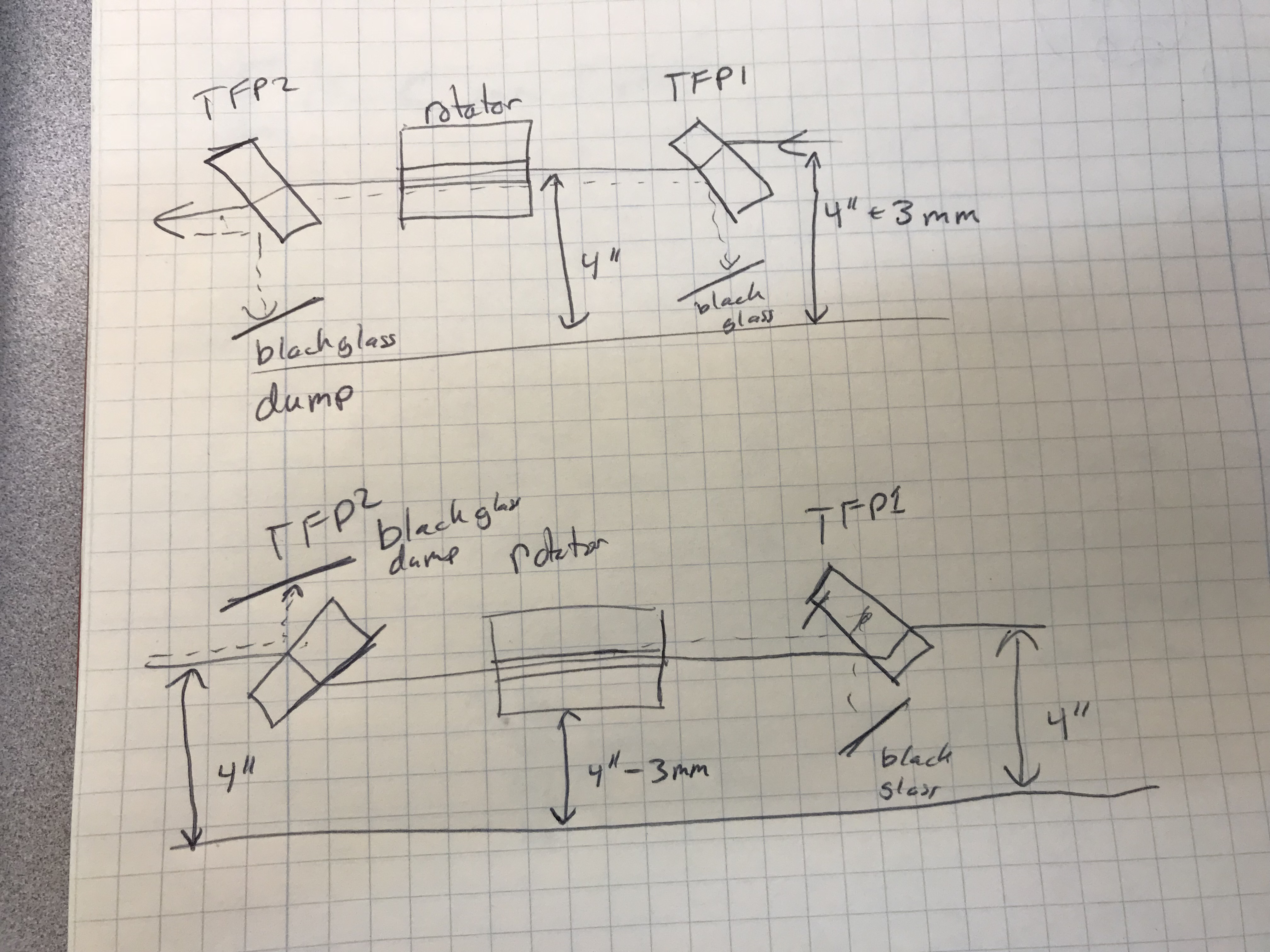
The thin film polarizers are 1/4 inch thick fused silica used at brewster's angle (56 deg), so they each deflect the beam down by about 2.8 mm as they are mounted. This means that we have almost a quarter inch difference in beam height across the Faraday isolator if we start with a level beam. Since the rotator aperture is only 5mm and it is mounted at 4 inches off the table, the beam needs to be a little high going into the first TFP and a little low coming out (top hand drawing in second attachment). Since the VOPO beam I think will be at 4 inches, we will have to steer it up then down again, which is possible. The bottom shows a suggestion for keeping the beam height into and out of the Faraday at 4 inches.
I have turned the PSL OFF, and it will remain in that state for the duration of the holiday break. I have also turned OFF the PMC, FSS, and ISS inner loop. In addition to this, at Peter's suggestion, I have also switched OFF the transimpedence chassis for the ISS second loop. The chillers have been left ON so that there is no standing water in the cooling lines of the laser. The PSL will be turned back ON on the morning of January 3rd, 2018. I hope everyone has a Happy Holiday!
In checking on the ETM optical levers prior to next month's vent, it was discovered that the ETMy optical lever was OFF, and had been for some time. I found that the laser had failed, so this afternoon I swapped in a spare. The serial number of the new laser is SN 189-2. Please note that this laser has NOT been tweaked for glitch-free operation; I simply swapped in a spare so that we have an alignment reference for the upcoming End-Y vent (I will swap in a tweaked laser once the end station work is done and I have had time to prepare one). Once this was done I re-centered the optical lever in preparation for the January vent and ETMy optic swap.
Looking back through trends, the ETMy oplev laser failed during the September power outage, and was just now swapped out. I will admit that during the corner station vent I have not been paying as much attention to the optical levers as I should have; this laser failure should have been noticed and corrected immediately, not 3 months after the fact, so this one is entirely on me.
Today I confirmed that all corner station optical levers are turned ON and that beams are on the QPD sensors. We decided to NOT re-center these optical levers in order to preserve the centering from the last time the IFO was locked. It should be noted that both the PR3 and SR3 optical levers required some tweaking to get the beam back onto the QPD. To preserve the previous centering of these optical levers, I tweaked the alignment via the launching telescope in the transmitter; therefore the (0,0) for both SR3 and PR3 optical levers represents the last time these oplevs were centered during O2 (the receivers have not been moved).
I do want to call out one thing. In investigating the SR3 optical lever (thanks Greg for climbing on top of HAM4 to direct my alignment!) we were having much difficulty in locating the beam; while it was on the QPD, there was no signal on the MEDM screen. It was discovered that the cable from the SR3 oplev whitening chassis to the CER had been unplugged in the CER. Looking through the alog, the best I can tell is this happened sometime between October 4 and October 12 (October 12 is the last time the oplev trends had a signal for SR3). This is something that should have, at a bare minimum, been noted in the alog, yet I can find no reference to any work involving the SR3 oplev and the CER during that time period. Thanks to Fil and Jeff K. for their help in tracking this down.
J. Kissel, T. Sadecki
Travis and I have taken close out transfer functions of H1SUSMC1, H1SUSMC2, H1SUSMC3, H1SUSPRM, and H1SUSPR2. After some hiccups with PR2 (aLOG pending), all suspensions look great. Note, PRM TFs were accidentally taken with extra TEST P&Y misalignment gains on the excitation, which is why it appears to have errantly high response.
Excellent work team!! We're ready to finish this vent!!
The data templates live here:
/ligo/svncommon/SusSVN/sus/trunk/HSTS/H1/
MC1/SAGM1/Data/2017-12-21_2155_H1SUSMC1_M1_WhiteNoise_L_0p01to50Hz.xml
MC1/SAGM1/Data/2017-12-21_2155_H1SUSMC1_M1_WhiteNoise_P_0p01to50Hz.xml
MC1/SAGM1/Data/2017-12-21_2155_H1SUSMC1_M1_WhiteNoise_R_0p01to50Hz.xml
MC1/SAGM1/Data/2017-12-21_2155_H1SUSMC1_M1_WhiteNoise_T_0p01to50Hz.xml
MC1/SAGM1/Data/2017-12-21_2155_H1SUSMC1_M1_WhiteNoise_V_0p01to50Hz.xml
MC1/SAGM1/Data/2017-12-21_2155_H1SUSMC1_M1_WhiteNoise_Y_0p01to50Hz.xml
MC2/SAGM1/Data/2017-12-21_2044_H1SUSMC2_M1_WhiteNoise_L_0p01to50Hz.xml
MC2/SAGM1/Data/2017-12-21_2044_H1SUSMC2_M1_WhiteNoise_P_0p01to50Hz.xml
MC2/SAGM1/Data/2017-12-21_2044_H1SUSMC2_M1_WhiteNoise_R_0p01to50Hz.xml
MC2/SAGM1/Data/2017-12-21_2044_H1SUSMC2_M1_WhiteNoise_T_0p01to50Hz.xml
MC2/SAGM1/Data/2017-12-21_2044_H1SUSMC2_M1_WhiteNoise_V_0p01to50Hz.xml
MC2/SAGM1/Data/2017-12-21_2044_H1SUSMC2_M1_WhiteNoise_Y_0p01to50Hz.xml
MC3/SAGM1/Data/2017-12-21_2155_H1SUSMC3_M1_WhiteNoise_L_0p01to50Hz.xml
MC3/SAGM1/Data/2017-12-21_2155_H1SUSMC3_M1_WhiteNoise_P_0p01to50Hz.xml
MC3/SAGM1/Data/2017-12-21_2155_H1SUSMC3_M1_WhiteNoise_R_0p01to50Hz.xml
MC3/SAGM1/Data/2017-12-21_2155_H1SUSMC3_M1_WhiteNoise_T_0p01to50Hz.xml
MC3/SAGM1/Data/2017-12-21_2155_H1SUSMC3_M1_WhiteNoise_V_0p01to50Hz.xml
MC3/SAGM1/Data/2017-12-21_2155_H1SUSMC3_M1_WhiteNoise_Y_0p01to50Hz.xml
PR2/SAGM1/Data/2017-12-21_2035_H1SUSPR2_M1_WhiteNoise_L_0p01to50Hz.xml
PR2/SAGM1/Data/2017-12-21_2035_H1SUSPR2_M1_WhiteNoise_P_0p01to50Hz.xml
PR2/SAGM1/Data/2017-12-21_2035_H1SUSPR2_M1_WhiteNoise_R_0p01to50Hz.xml
PR2/SAGM1/Data/2017-12-21_2035_H1SUSPR2_M1_WhiteNoise_T_0p01to50Hz.xml
PR2/SAGM1/Data/2017-12-21_2035_H1SUSPR2_M1_WhiteNoise_V_0p01to50Hz.xml
PR2/SAGM1/Data/2017-12-21_2035_H1SUSPR2_M1_WhiteNoise_Y_0p01to50Hz.xml
PRM/SAGM1/Data/2017-12-21_2155_H1SUSPRM_M1_WhiteNoise_L_0p01to50Hz.xml
PRM/SAGM1/Data/2017-12-21_2155_H1SUSPRM_M1_WhiteNoise_P_0p01to50Hz.xml
PRM/SAGM1/Data/2017-12-21_2155_H1SUSPRM_M1_WhiteNoise_R_0p01to50Hz.xml
PRM/SAGM1/Data/2017-12-21_2155_H1SUSPRM_M1_WhiteNoise_T_0p01to50Hz.xml
PRM/SAGM1/Data/2017-12-21_2155_H1SUSPRM_M1_WhiteNoise_V_0p01to50Hz.xml
PRM/SAGM1/Data/2017-12-21_2155_H1SUSPRM_M1_WhiteNoise_Y_0p01to50Hz.xml
F. Clara, J. Kissel, R. McCarthy, B. Weaver Proving that doors-on is always when the crazies come out of the wood-work, PR2 also showed a similar relay failure mode as PR3 (LHO aLOG 39540, LHO aLOG 39878, FRS Ticket 9497) when we first started checking its close out transfer functions. However, PR2 had failed in the opposite direction, with its T3 OSEM failed with the low pass ON (i.e. binary HIGH). We tried first to re-seat cables in the in-vac side of the feedthru, suspecting that ground loop investigations had left cables a little wonky. Didn't fix it. After that, we'd remembered PR3 problems, and went to PR2's coil driver. However, the fix only required disconnecting and reconnecting the binary IO input cable to the coil driver (yuck!). Attached are - Screenshot of how I found it -- the BIO screen showed the T3 OSEM coil driver state was not like the others. - Screenshot of the top mass Pitch to Pitch transfer function the revealed the problem. BLACK is nominal, RED is with T3 OSEM coil driver channel in the wrong analog state. But, as mentioned above, all is clear now. We did not need to change out any coil drivers.
Evan G., Rick S. We transitioned the EY VEA to laser hazard and then turned on and unshuttered the EY Pcal laser (previously turned off before the Thanksgiving break). Next we checked the positioning of the two beams on the receiver module relay mirrors. The outer beam mirror required more adjustment than the inner beam mirror. The positioning was adjusted to center the Pcal beams and both beams were aligned to the center of the integrating sphere aperture. After this procedure, we shuttered the laser, turned it off, and transitioned the EY VEA back to laser safe. This work was done in preparation for the EY vent to take place in January.
New TFs match well with previously healthy TFs taken in July. Results can be found at:
/ligo/svncommon/SusSVN/sus/trunk/HLTS/Common/Data/allhltss_2017-12-21_H1_HLTS_Phase3a_PR3_M1_Doff_ALL_TFs.pdf
/ligo/svncommon/SusSVN/sus/trunk/HLTS/Common/Data/allhltss_2017-12-21_H1_HLTS_Phase3a_PR3_M1_Doff_ALL_ZOOMED_TFs.pdf
Snaps attached of P and Y for example.
F. Clara, J. Kissel, R. McCarthy Sadly, we'd battled a bit of confusion while taking these close out TFs -- namely, that the T3 OSEM on the TOP coil driver that had failed earlier in the vent (see LHO aLOG 39541 FRS 9497) caused further problems manifesting as a *slight* change in the Pitch response of the top 2 top transfer functions (see attached screenshot). Rather than investigate thoroughly, we just swapped the coil driver with a spare. We'll include more details in the FRS after bench testing the failed driver. For now, PR3 remains with a temporary spare on one of its two TOP coil drivers. Attached is the pitch-to-pitch transfer function that revealed the problem. BLACK -- Prior to vent MAGENTA -- during T3 coil driver problem RED -- after problem was resolved
WP7252:
During today's CDS meeting Rolf reported that moving the fast front-end computer's IRIG-B card away from slot-1 resolved timing issues on his test system. To try this out on a production system, this afternoon I moved h1susey's IRIG-B card.
Recall (alog 39361) that on 09nov2017 I had moved h1susey's OneStop from slot-2 to slot-5 as part of this investigation. Today I returned the OneStop back to slot-2, and moved the IRIG-B card from slot-1 to the newly vacated slot-5.
| slot id | 7 | 6 | 5 | 4 | 3 | 2 | 1 |
| before | empty | empty | OneStop | 5565 | Dolphin | empty | IRIG-B |
| after | empty | empty | IRIG-B | 5565 | Dolphin | OneStop | empty |
It was a messy restart of h1susey. After taking it out of the Dolphin fabric and issuing the poweroff command, the OS got stuck trying to umount NFS after apparently disabling its network ports. I had to power down using the front panel button, knowing that this would most probably cause a Dolphin glitch. Sure enough, on restoration of power the EY dolphin fabric glitched, requiring a restart of models on h1seiey and h1iscey. EY is now back in operation.
Tagging DetChar, so it's on their record books that this change was made.
The upcoming front-end OS upgrade (Gentoo with 3.0.8 kernel) has a much cleaner startup/shutdown process that works with the OS instead of fighting with it. This should help those issues.
I also took the opportunity to move the eyws1 iMac workstation to EY. It is located on a cart parked by the computer racks.
Unfortunately there were two h1iopsusey blips this morning at 03:20 and 06:02 PST.