Displaying reports 49561-49580 of 87662.Go to page Start 2475 2476 2477 2478 2479 2480 2481 2482 2483 End
Reports until 12:07, Monday 30 October 2017
LHO VE
chandra.romel@LIGO.ORG - posted 12:07, Monday 30 October 2017 - last comment - 11:53, Tuesday 05 December 2017(39208)
unknown contaminant on vacuum wall of XBM

Travis and I walked down X-beam manifold in chamber to investigate unknown contamination on the interior wall that Betsy had spotted, a few feet away from oplev flange/baffle. We found two dark brown/black spots near the top/roof of tube, each about the size of a quarter. I was able to scrape some off with a little flat head screw driver and then wipe with IPA wipes to improve/reduce the spots (grinding is needed to remove all). Before and after pictures attached. I wiped until there was no evidence of contaminate on wipe. Then we noticed the side wall was splattered with the same material (photo attached). Its first layer comes off by scraping with a tool, but we did not spend time scraping all 50-some spots. We can go back in to scrape these other spots, but I would first like to send sample in for analysis.

Note that we have seen evidence of higher pressures in XBM (compared to YBM) when it's isolated from beam tube. Could be outgassing from this material. Travis and I inspected YBM and did not find this contaminate.


Images attached to this report
Comments related to this report
chandra.romel@LIGO.ORG - 11:53, Tuesday 05 December 2017 (39638)

JPL results here:  https://dcc.ligo.org/E1700405

  • Particles showed a reddish / brown, flakey appearance when viewed at magnification.
  • Analysis by x-ray fluorescent microscope showed the particles to consist mainly of Iron. The results are shown in the table below.
  • Iron oxide was detected by Raman Spectroscopy.
LHO FMCS
bubba.gateley@LIGO.ORG - posted 10:26, Monday 30 October 2017 - last comment - 11:31, Monday 30 October 2017(39206)
HVAC Controls Upgrade
Late last week, we took control of AHU 1 & 2 in the LVEA with the new HVAC controls. This has been a long process and is actually still on going in so far as we still have to take control of AHU-3. 
I have been monitoring the LVEA all weekend and in an effort to stabilize the temperatures even more, this morning I have increased the air flows in the LVEA from ~12,000 cfm per air handler to ~18,500 cfm. This has already made a considerable improvement and I will continue to monitor.
Comments related to this report
patrick.thomas@LIGO.ORG - 11:31, Monday 30 October 2017 (39207)
MEDM screens have been updated.
H1 PSL
edmond.merilh@LIGO.ORG - posted 08:58, Monday 30 October 2017 (39203)
PSL Weekly Report - 10 Day Trends FAMIS #6172

Everything appears to be "business as usual". There are very marginal downward trends in the osc pressures  and amp flow.

Images attached to this report
H1 PSL
edmond.merilh@LIGO.ORG - posted 08:42, Monday 30 October 2017 (39202)
PSL Status Report - Weekly: FAMIS #7462

Laser Status:
SysStat is good
Front End Power is 35.89W (should be around 30 W)
HPO Output Power is 153.9W
Front End Watch is GREEN
HPO Watch is GREEN

PMC:
It has been locked 10 days, 18 hr 36 minutes (should be days/weeks)
Reflected power = 23.33Watts
Transmitted power = 48.29Watts
PowerSum = 71.62Watts.

FSS:
It has been locked for 0 days 4 hr and 47 min (should be days/weeks)
TPD[V] = 2.786V (min 0.9V)

ISS:
The diffracted power is around 2.7% (should be 3-5%)
Last saturation event was 5 days 23 hours and 10 minutes ago (should be days/weeks)

Possible Issues:
PMC reflected power is high


H1 General
edmond.merilh@LIGO.ORG - posted 08:32, Monday 30 October 2017 - last comment - 12:14, Monday 30 October 2017(39200)
Shift Transition - Day

TITLE: 10/30 Day Shift: 15:00-23:00 UTC (08:00-16:00 PST), all times posted in UTC
STATE of H1: Planned Engineering
OUTGOING OPERATOR: None
CURRENT ENVIRONMENT:
    Wind: 17mph Gusts, 12mph 5min avg
    Primary useism: 0.06 μm/s
    Secondary useism: 0.28 μm/s
QUICK SUMMARY:

14:18 Kissel in early to do some more B&K hammering in HAM2


Comments related to this report
edmond.merilh@LIGO.ORG - 12:14, Monday 30 October 2017 (39210)

15:33 (HFD) MSA on site for Bubba

16:05 Kissel out for vent meeting

16:12 more MSA on site for RFAR testing

16:44 Gerardo is in the HAM5 area

16:55 Chandra going in chamber with Betsy and Travis - X Manifold

16:57 Travis heading out to biergarten

17:10 Betsy ou to he biergarten

17:15 Gerardo is out

17:25 Gerardo and Peter into Optics lab

17:27 Fil out to LVEA to put plastic conduit arounf fibers that were pulled on Friday

17:43 Job Shadow student on site

17:44 TJ heading out to HAM 4/5 area.

17:55 Richard and shadow student into LVEA for tour

18:08 Greg into LVEA to take measurements for TCS table

18:18 Kyle to the Y end station

18:27 Noise Eater out of range alarm

18:54 Travis out to reset the Noise Eater

19:13 I will be turning ops over to Corey so I can assist with HAM2 in-chamber work

H1 PEM (DetChar)
robert.schofield@LIGO.ORG - posted 18:04, Sunday 29 October 2017 (39199)
Site-wide maximum magnetic coupling functions for LHO and LLO

Members of the Stochastic Group have expressed interest in magnetic coupling for estimates of Schumann Resonance coupling during O2. Automated coupling functions for all injections are not quite ready to be posted at pem.ligo.org, so we are going ahead and posting site-wide magnetic coupling functions from the August 2017 PEM injections here.

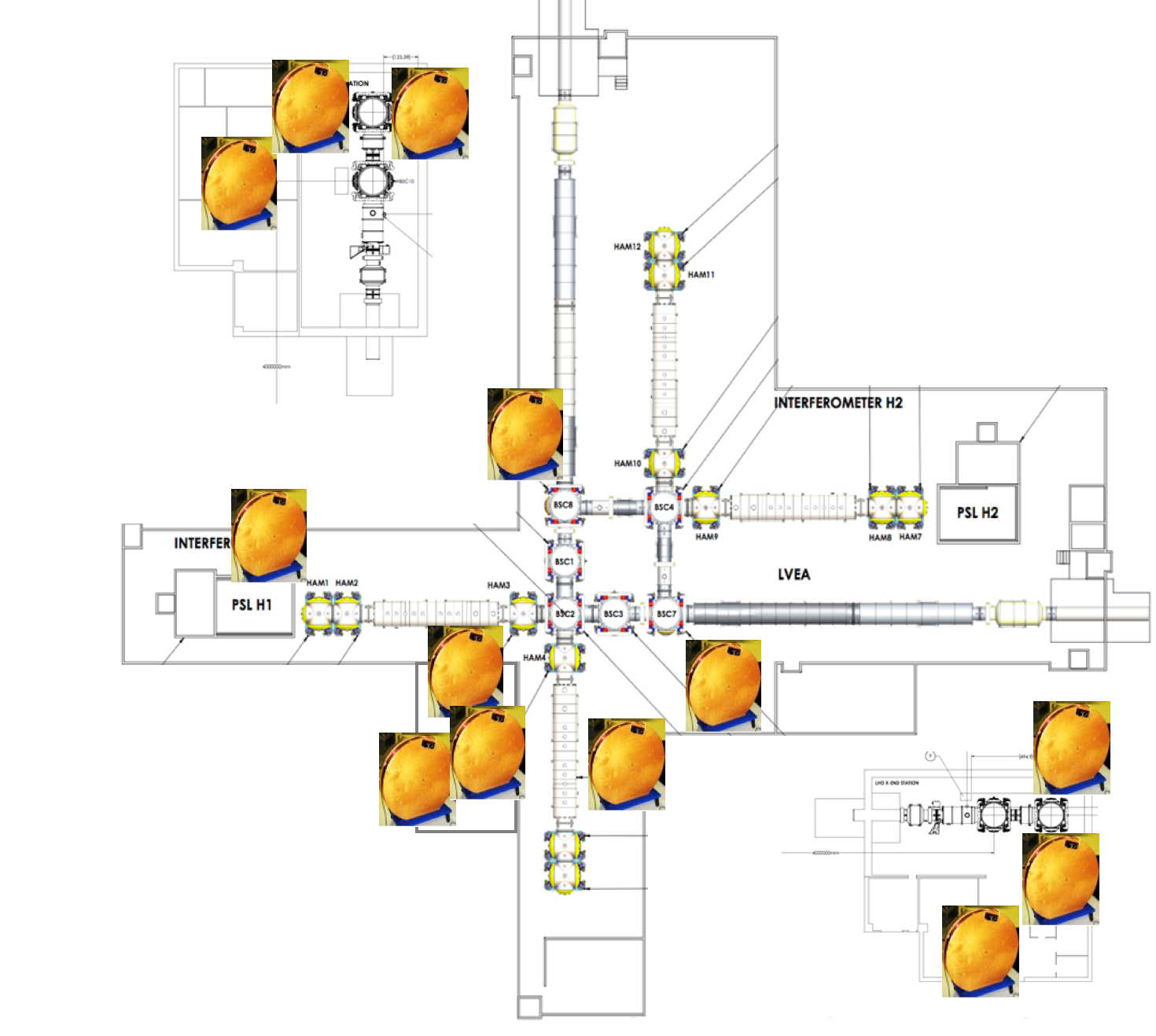
Magnetic field injections were made at multiple locations in all 3 LVEA/VEAs and electronics rooms. The LHO injection locations are shown in the first figure below and the injection locations at LLO are similar. The code (started by Julia Kruk and completed by Philippe Nguyen) used the following procedure:

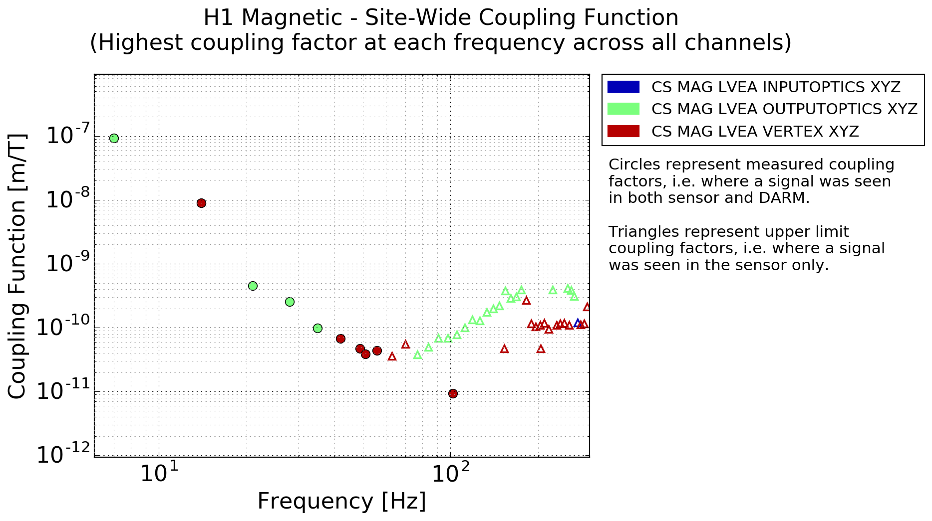
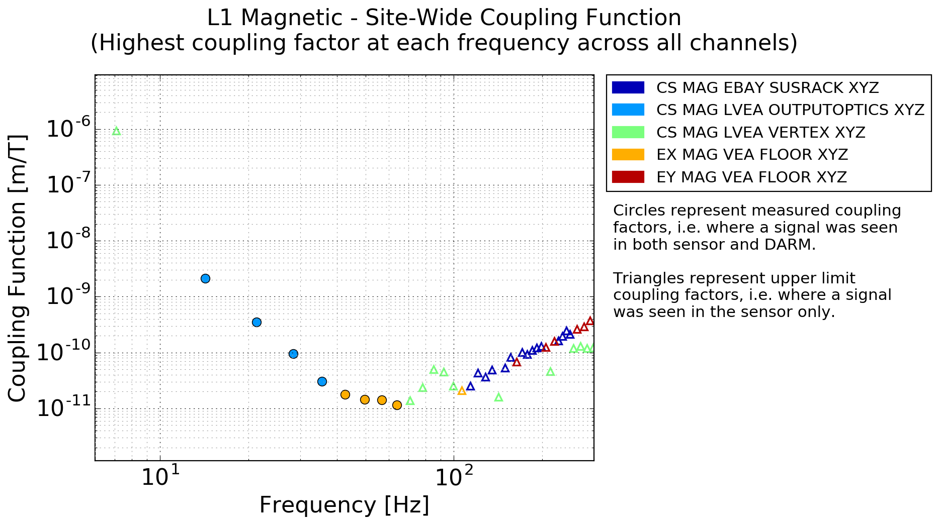
1) Coupling functions (meters of DARM per Tesla) were calculated for each magnetometer (the quadrature sum of the axes), for each of multiple injections in the local area (LVEA/VEA or electronics bay). The coupling function is the DARM signal divided by the magnetometer signal.

2) The coupling functions for each injection for each sensor were narrowed down to a single coupling function for each sensor by picking the minimum coupling factor at each frequency. Selecting the minimum coupling factor eliminates excessively high upper limit coupling factors for sensors that are far from the injection and coupling sites and thus detect small fields for large DARM signals.

3) For the site-wide maximum coupling function given here, the maximum coupling factor at each frequency is picked from the coupling factors for all of the sensors on the LHO/LLO site.

Of course, site coupling will be the combination of coupling at all coupling locations within each site - this is just the largest of these at each frequency. We think that the largest coupling factor is probably a fair estimate for the site because other coupling locations with lower couplings can increase or decrease the overall coupling. But the coupling functions here could be multiplied by a factor like sqrt(2) to be conservative.

Other issues:                                                                               

There was a large change in magnetic coupling during O2 at LHO, as noted in: https://dcc.ligo.org/DocDB/0144/G1701613/002/GenevaTalkSm.pdf , and we don’t know when it happened. I think that, as Schumann Resonance coupling becomes more important, we should probably push for a continuous magnetic injection at each station, like a calibration line, or at least weekly injections.  Back when our magnetic coupling was dominated by permanent magnets on the test masses, it didn’t change for years. But now we tend to be dominated by coupling to cables, and this can change dramatically as electronics and cables change. After talking with Richard M., my best guess is that the change happened May 16th when the ITM ESD power supplies were changed, but that is just a guess. For S3 it might be a good idea to set up a single continuous line injection at the LHO corner station in order to better study coupling variation.

Another consideration for Schumann Resonances is the eddy current shielding due to the steel skin of the buildings. This is not included in these coupling functions because the injection was from within the building. We should measure this, but assuming it is the same as for a chamber, it would be about: 1/sqrt(1 + (f/20)^2), or a factor of 0.93 at 8 Hz and 0.55 at 60 Hz.

Philippe Nguyen, Julia Kruk, Anamaria Effler, Robert Schofield

Images attached to this report
Non-image files attached to this report
LHO VE
kyle.ryan@LIGO.ORG - posted 18:33, Friday 27 October 2017 - last comment - 11:13, Saturday 28 October 2017(39193)
Y2-8 ion pump off for unknown reason
I noticed a pressure "bump" at Y-end recently and have now confirmed that the ion pump mounted at BT port Y2-8 has been off for the past few days.  Today's troubleshooting including re-enabling the High Voltage output.  This resulted in power limited (700V @ 0.5 amp) energization (no ion pumping while inadequately energized).  Next, the HV cable was moved to he other HV channel with a similar result.  The controller-end of the HV cable was disconnected and a VOM used to measure the cable+pump resistance (2.5 Mohm, insufficient output voltage of the meter makes this test "almost" useless).  The HV cable was reconnected to the controller and the pump-end disconnected. In this configuration, the controller wouldn't output HV as the cable connector shield wasn't grounded and, it would seem, the cable isn't shorted.  

I noticed that the pump-end of the HV cable was noticeably "warm" after applying 700V at 0.5 amps.  This observation combined with the interpretation that the cable or pump-end connector aren't shorted indicates that the low resistance is internal to the pump itself.  Ahhh!  The fabled "whisker" theory.  

Monday, we will adapt a custom HV cable and use the "Big Gun" 10,000V 600 watt power supply to, hopefully, vaporize any troublesome whiskers that have formed between the electrodes.  


Comments related to this report
john.worden@LIGO.ORG - 06:36, Saturday 28 October 2017 (39194)

The pump is probably in a condensing environment at times so there may be conductive buildup on the pump feedthrough or the interior of the cable connector. 

I would be surprised at whisker buildup as that pump has not pumped significant gas loads. 

Also, I would fake out the interlock at the pump and make sure you can get high volts on the cable alone.

kyle.ryan@LIGO.ORG - 11:13, Saturday 28 October 2017 (39195)
Yes, I'll disconnect the pump-end connector and then ground the shield.  This should satisfy the controller and get it to energize the HV output.  As John W. points out, the pump-end connector shorting would explain why it was warm and is much more likely than the pump being internally shorted when considering the pumps torr*L exposure history.  
H1 AOS (AOS)
gerardo.moreno@LIGO.ORG - posted 17:45, Friday 27 October 2017 - last comment - 17:58, Friday 27 October 2017(39191)
OFI Update

(Peter K, Gerardo M)

New OFI table is suspended in cage, some components on the cage assembly were loose, they were re-torqued.  The missing corner bracket was installed, and we replaced a couple of bad 1/4-20 flat head socket head cap screws.

Next, table balance and suspension damping.


Images attached to this report
Comments related to this report
kyle.ryan@LIGO.ORG - 17:58, Friday 27 October 2017 (39192)
What is the tan colored staining from?  These are Class-A parts?
H1 IOO (DetChar, IOO, ISC, SEI, SUS)
jeffrey.kissel@LIGO.ORG - posted 17:05, Friday 27 October 2017 - last comment - 11:58, Sunday 29 October 2017(39190)
HAUX (IM) B&K Data Processed: Torquing makes Cage Resonances Higher (IM4 Remains Low), Much Better than L1's IMs; Could Use Cage Damping?
J. Kissel, C. Vorvick

I've processed the data from last week's first B&K adventure into HAM2 which included the HAUX (a.k.a. HAM Auxiliary Suspensions, a.k.a. IMs or Input Mirrors) (LHO aLOG 39096). 

Recent efforts tightening and torquing the cage bolts to spec (e.g. LHO aLOG 38808) has helped increase the resonance frequencies and Qs of the first bending modes of cage to ~170 Hz in Longitudinal and 220 Hz in Transverse.

These modes are significantly better* than those at L1. 
*Here, by "better" I mean well-defined, high resonance frequencies, and features are similar between suspensions.
The data I use from LLO is the same as posted in LLO aLOG 3948 for IMs 1,2, and 4 from their 2012 vent, and the more recent LLO aLOG 25919 for the problematic IM3 from 2016. 

After discussing with Cheryl, there are several differences that elucidate this difference. 
(1) While LLO has used the "IO" dog clamps of several varieties (D1100640), LHO has used the champhered-ended "SUS" dog clamps (D1100641). These create a more well-defined contact point. 
(2) In addition, the layout of dog clamps around the base of the cage is significantly different; LHO revised the original layout, seeing how unstable the originally prescribed appeared. See table below for comparison of layouts:

Current   Former      Original    Revised
Name      Name        Layout      Layout
                      (LLO)       (LHO)
IM1       SM1         D1200623    T1400742
IM2       PMMT1       D1200625    T1400743
IM3       PMMT2       D1200626    T1400744
IM4       SM2         D1200624    (not revised)

Further confirming the difference -- IM4's clamping configuration does use the IO clamps, in a similar arrangement, and the frequency responses of the cage between H1 and L1 look quite similar -- in Longitudinal, but Transverse remains quite different.

In light of this data, I propose two things:
(1) At the earliest convenience (if there is still such convenience left), we should ECR Cheryl's improvements, implement them at LLO, and update documentation such that India gets similar benefit.

(2) Now that we've stiffened up the resonances, they've become higher Q. We should consider shoving some viton in between the suspension cage, and, say, each of its black-glass cage baffles. It shouldn't need much.
Non-image files attached to this report
Comments related to this report
cheryl.vorvick@LIGO.ORG - 11:10, Sunday 29 October 2017 (39197)

IM4 would likely benefit from additional SUS dog clamps.  I'm looking into where they could be installed.

I'm also looking in to options for viton.

The baffles are SiC, and it may be possible to install viton in direct contact with them, but the brittle nature of SiC may not allow for this.

A possible location for installing viton is on the stiffening plate in the cage, which has two 1/4-20 bolt holes available on all of the IMs.  These bolt holes are above the SiC baffles, so not near the beam.  If viton installed here can effectively damp the resonances, this would be a minimal change to the IM cages.

I've attached a couple drawings of the IM cage stiffening plate and a picture of IM4 showing the available bolt holes.

Images attached to this comment
cheryl.vorvick@LIGO.ORG - 11:58, Sunday 29 October 2017 (39198)

Here are pictures from my original SUS dog clamp installation on IM4, before the SiC baffle was installed.

Images attached to this comment
LHO General
corey.gray@LIGO.ORG - posted 16:04, Friday 27 October 2017 (39186)
DAY Operator Summary

Day's Log Of Activities:

H1 SUS
betsy.weaver@LIGO.ORG - posted 15:13, Friday 27 October 2017 (39189)
ITMX alignment continues

Never closer.  Another day in the tank aligning the ITMX main and reaction chains to the oplev, while simultaneously keeping all 132 potential mechanical interferences clear.  COB right now and we have something still rubbing.  Boo.


Also, the ITMY is mechanically rubbing somewhere too.  More next week.

H1 CDS (SEI)
edmond.merilh@LIGO.ORG - posted 13:37, Friday 27 October 2017 (39185)
Corner Station H1 ISI Coil Drivers Updated

All Corner Station H1 ISI Coil Driver chassis were removed from their racks and modified in trhe EE lab as per ECRs E1100821 & E1300535 .   These mods also include the swapping of a wire on the temp reset switch from the "normally closed" position to the "normally open" position. Also, a number of the surface mount +15VDC indicator LEDs were installed incorrectly and would not illuminate.

Chassis S1103566 in SEI rack C1 doesn't have the "keyed" 24VDC connector. It has the typical +/- 18VDC config and associated power cable.

Chassis S1103363 (HAM2) in SEI rack C2 was noted as having a -15V led not illuminated. Upon further investigation it was found to have a bad 7915 regulator which is what E1300535 was implemented to prevent.

All chassis were re-installed and are powered up. SEI team was informed. E-travelers will be updated.

H1 SYS
thomas.shaffer@LIGO.ORG - posted 16:33, Wednesday 25 October 2017 - last comment - 09:39, Monday 30 October 2017(39170)
HAM2 baffles all finished up

J. Warner, S. Appert, T. Shaffer

We had some unexpected time to work on HAM2 baffles after some FedEx kerfluffles, so Jim and I went into HAM2 with some freshly baked parts and an engineer (just in case things got out of hand). This work went really fast with the three of us and we managed to finish up PRM, the last beard baffle, align all of the panels we needed to, and then torque and cap everything. I went into the beam tube to work from there and to be the eyes to align, and of course, I wiped on my way out.

We left the table baffle that sits in front of PR3 off the table for now, but with the mounts bolted down. This way the other crews that still need to do work have a little bit of space to work and won't scratch anything, hopefully. To place this last panel will take only a minute or two so we can easily do it after the major work is all done.

Pictures to come.

Comments related to this report
thomas.shaffer@LIGO.ORG - 09:38, Monday 30 October 2017 (39204)

Attached photos of the baffles on HAM2. The table baffles in front of PR3 are waiting to be installed, as the pictures will reflect.

Images attached to this comment
thomas.shaffer@LIGO.ORG - 09:39, Monday 30 October 2017 (39205)

Two more.

Images attached to this comment
Displaying reports 49561-49580 of 87662.Go to page Start 2475 2476 2477 2478 2479 2480 2481 2482 2483 End