Displaying reports 49821-49840 of 88171.Go to page Start 2488 2489 2490 2491 2492 2493 2494 2495 2496 End
Reports until 08:57, Friday 17 November 2017
H1 SEI
hugh.radkins@LIGO.ORG - posted 08:57, Friday 17 November 2017 (39465)
New Beckoff data for EndX HEPI Pump Pressures

Patrick got the new Beckoff controller running at the end station.  The old servo controller is still in place and still running the PID controlled VFD.  The Beckoff is just looking at the pressure transducers on the PS skid which are out of loop for the PID.

The attached plot shows the old and the new (different name) channels on the same plot through amazing wizardry!  Come on, it's about all I have. 

The Beckoff ADC is used much more efficiently than the Athena in the old box.  The Beckoff range is 75mV while the Athena is +-10V for a signal that should never exceed 50mV and nominally run about 20mV.

Clearly the time series is much better for the Beckoff with much tighter range and a lot less hair.  This might further improve when the VFD is controlled by a cleaner channel.  There have been times in the past where the old controller produced cleaner data than it does now but I don't think it was ever any cleaner than this data.

Next, maybe while I change the filters, we'll transition the PID to the Beckoff.

Images attached to this report
H1 INS (INS, ISC, SQZ, SUS)
keita.kawabe@LIGO.ORG - posted 18:08, Thursday 16 November 2017 - last comment - 21:02, Thursday 16 November 2017(39460)
IO-PRC-SRC-OFI-OM1 and -ZM2 alignment (Siddhesh??, Brijesh??, JeffK, Koji, Gerardo, Keita)

1. IM4 and IOO PZT

Before doing anything the beam was already coming to the OFI. We centered the beam on OFI input aperture using BS just so that it's easier for us to eyeball the beam motion.

We removed the PIT offset just enough so that the output wouldn't rail and IM4 is properly damped. (This happened to be the slider MEDM limit of -25000.)

We used IOO PZT to bring the beam back to the center of OFI input.

2. SR2-SRM-OFI

We used BS to center the beam on SR2, then used SR2 to center the beam on SRM. Centering accuracy claimed by Siddhesh??, Brijesh??, JeffK, and later confirmed by Koji, is a couple of mm on SR2 and less than a mm on SRM.

The beam was off in PIT by negligible but measurable amount (0.5mm) on the input aperture of the OFI, but a couple of mm too low on the output aperture.

Gerardo adjusted the OFI SUS to lower the output side of the OFI and it's within 0.5mm for PIT on both the input and output of OFI, but a mm or so in YAW at the output. This might sound small to you but we'll fix it for the reason explained in 4.

3.  OFI-OM1 craziness of O1/O2 seems to be gone, but this means that the septum window needs to be rotated (again).

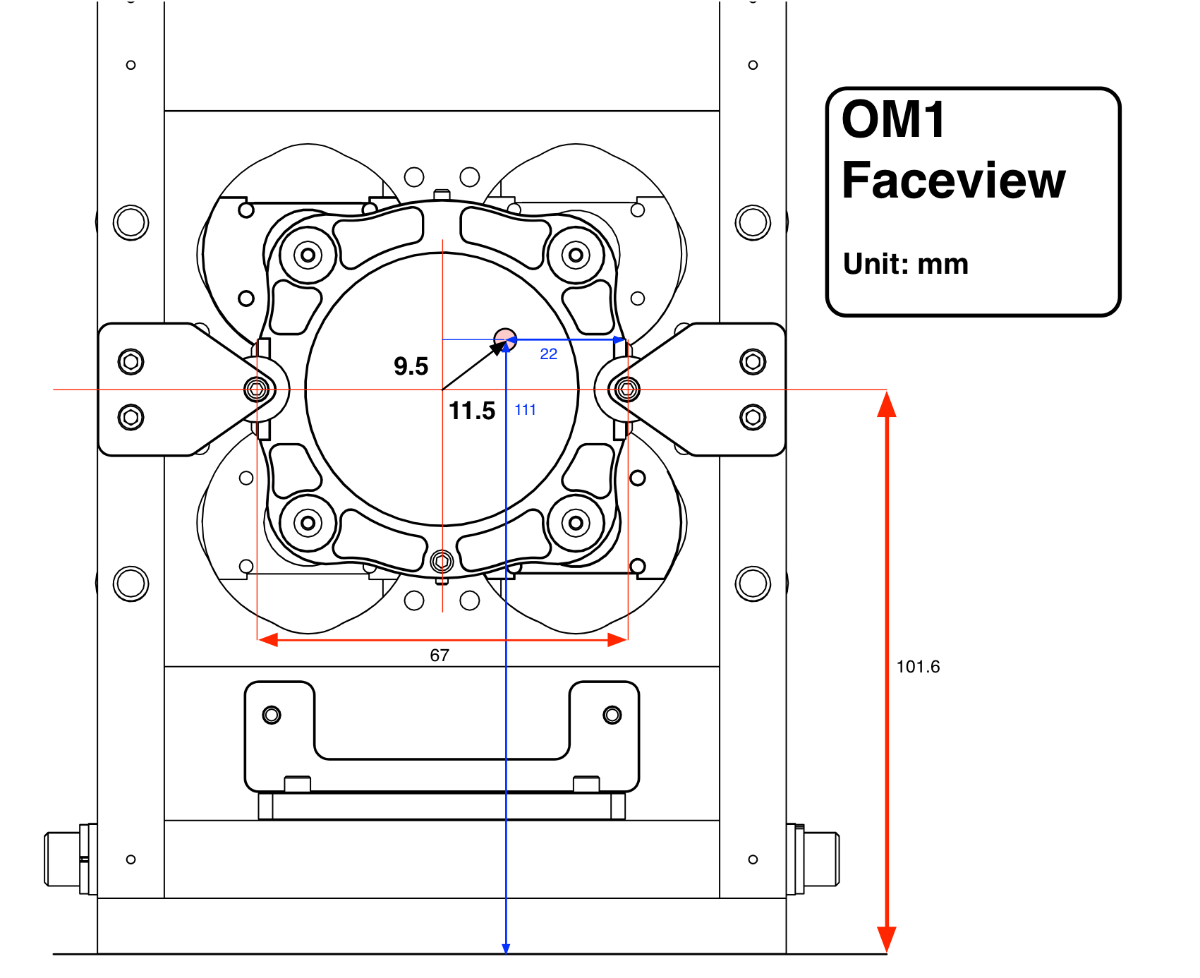
We found that the beam on OM1 was about 9mm too high and 12mm off to the side. See Koji's attachment to this log.

Back in the day before O1, the beam was 10.6mm too low on OM1(alog 13391)

Again back in the day, to fix this craziness the septum window needed to be rotated by 120 degrees clockwise, and this got the beam back to the right height on OM1. (alog 13477)

Changing the Faraday (or maybe something else) should have fixed the root cause of the craziness. But this means that the septum window should be rotated back by 120 degrees counter-clockwise. This will set the septum plate angle as designed, the beam height on OM1 should become about right.

OM1 position should be also shifted sideways to accommodate the yaw change caused by this. Which means that the OM1 and OM2 alignment needs to be mechanically moved in YAW.

4. OFI-ZM2 alignment is totally wrong, OFI YAW alignment should be revisited. 

Right now, when we install the additional HWP, the rejected beam from OFI is blocked by the Faraday rotator. The beam is not centered on the first steering mirror in YAW to start with though it's not clipping, it's close to the edge of the the second steering mirror, and the reflection from the secod mirror directly goes to the rotator.

We could adjust the steering mirror position and angle and be done with it, but Koji felt that we should align the OFI in yaw before moving the steering mirror, especially the position of the mirror mount.

Tomorrow.

I will NOT transition LVEA to laser safe tonight.

Comments related to this report
keita.kawabe@LIGO.ORG - 18:16, Thursday 16 November 2017 (39463)

slider numbers.

Images attached to this comment
koji.arai@LIGO.ORG - 21:02, Thursday 16 November 2017 (39464)

Here somewhat more precise evaluation of the beam spot on OM1.
The beam is off from the center of OM1 by 11.5mm (up) and 9.5mm (right) in horiz. and vert directions, respectively.
See attached figure.

Images attached to this comment
H1 AOS (AOS, SQZ)
gerardo.moreno@LIGO.ORG - posted 18:01, Thursday 16 November 2017 (39462)
HAM5 OFI Update

(Koji A, Keita K, Gerardo M)

Beam is going all the way to HAM6, but the OFI is going to need some small adjustment to declare it good, 1 mm push towards global +X at the output side only, to be done tomorrow.

As of right now, the LVEA remains in laser hazard.

H1 PSL (ISC)
sheila.dwyer@LIGO.ORG - posted 17:18, Thursday 16 November 2017 - last comment - 17:46, Thursday 16 November 2017(39434)
PMC jitters suppression a factor of 2 worse than it should be (based on coherence)

There is half as much jitter attenuation as we expect from the PMC.  Since broad band jitter noise from the HPO has been limiting our sensitivity (in addition to acoustic jitter peaks which are imposed after the PMC), it is worth understanding the jitter attenuation we get from the PMC and fixing it if possible. I originally wrote this alog after looking at data from September 11th, however the bullseye QPD seems to have been misaligned or somehow otherwise changed while people were in the PSL for maintenance period on August 29th.  This lead me to the seemingly impossible conclusion that the PMC was letting 33 times more jitter through than it should. 

I looked at a period of time when the mode cleaner was misaligned and unlocked on July 18th 2017, starting around 2:05:00.  

One possible explanation would be that the coherence is explained by something other than jitter coupling through the PMC, like residual intensity noise or acoustics on the table, but neither of these seem to be the case (second attachment, bottom left).  There is no coherence of the WFS PIT with the SUM, which rules out intensity noise, and the table accelerometers have good coherence at the frequencies where the bullseye is not coherent (at resonant frequencies of optical mounts table acoustics explain the jitter, but not at the frequencies where the bullseye coherence is highest).

The third attachment shows that the spectrum of IMC WFS B (uncalibrated, taken with the IMC locked) has gotten noisier towards the end of O2. 

It would be good to realign the bullseye or replace it with the new version and check that it is well aligned and that the beam size is correct. After the in chamber work with the IMC bypass is finished, we can repeat this measurement with more power.  

It looks like our PMC does not attenuate jitter as much as it should, I think about 33 times less than it should. 

The PMC should attenuate pointing jitter by 0.0163 for yaw and 0.0144 for pitch according to T0900616.  

The first plot shows spectra and coherences from a time (only about a minutes and a half long) when there was 2 W into the IMC but MC2 was misalinged.  The IMC WFS DC are then calibrated in to beam widths.  The bullseye QPD is calibrated in to beam widths in the front end, (34625) in this plot I've added a factor for the attenuation we expect from the PMC.  The bullseye shows jitter that comes from the HPO with a smooth spectrum, which should be well below the measured noise on the IMC WFS with the attenuation from the PMC.  In the lower panel you can see that the Bullseye has rather high coherence with IMC WFS B PIT, suggesting that the jitter is not attenuated as much as it should be by the PMC. 

At 200 Hz,it looks like the PMC is only attenuating the jitter by about 0.47.  The WFS B PIT has 1.2e-6 1/rt Hz at 200 Hz, and a coherence of 0.5 with the bullseye, so the noise seen by the bullseye is at about the level of 8.5e-7.  The bullseye pit is 1.8e-6 /rt Hz at 200 Hz (without the rescaling I've done in the attached plot). 

Edit:  The coherence of the WFS B Pit with the bullseye cannot be explained by residual intensity noise in the pit signal which is coherent with the jitter noise.  I've updated the plot to include a trace that shows no coherence between WFS B sum and WFS B pit. 

Second edit:  The bullseye QPD was misalinged during the maintence window on August 29th, so this result be misleading.  

Images attached to this report
Non-image files attached to this report
Comments related to this report
sheila.dwyer@LIGO.ORG - 18:57, Tuesday 14 November 2017 (39435)

I ran a couple of PMC scans.  Some good data should start at around 15/11/2017 at 2:50:57 UTC.  The largest higher order mode is a 20 mode, with about 1/4th the power that is in the 00 mode. 

jason.oberling@LIGO.ORG - 17:46, Thursday 16 November 2017 (39461)

It should be noted that the only maintenance on the PSL on August 29th was done entirely from the control room, no PSL incursion was made.  Looking into it further, there are no alogs from that day indicating a PSL incursion was made (or on the preceeding Monday or following Wednesday), and the operator's daily activity log also indicates that no incursion was made.  At this point in time we do not know why the bulls-eye PD became misaligned.  Peter King is going into the enclosure tomorrow (11/17/2017) for something unrelated and has agreed to take a look at the bulls-eye PD to see if anything is amiss.

H1 SEI
sam.cooper@LIGO.ORG - posted 16:36, Thursday 16 November 2017 - last comment - 13:51, Friday 17 November 2017(39455)
Number of watchdog trips per subsystem during O2

S Cooper, S Dwyer, J Warner, 

Attached in this alog are some overviews of the total number of watchdog trips by subsystem (HEPI,ISI,SUS) per chamber over the course of O2 for some known large earthquakes. We get this data by looking at the state of the watchdogs for each subsystem over the course of two hours during an earthquake using minute trended data. To generate these plots we look at the WD_MON State channels and just check for if they ever deviate from their ideal value (1 in most cases) and sum the number of events that these trip. We also pull the interferometer lock state to a) monitor lock losses and b) to veto any trips caused by frontend crashes rather than earthquakes. 

Also attached is some comma delimited text files containing information on which of these watchdogs tripped first for each earthquake, with a list of GPS times listed for each of these events. Note, again because of the minute trended nature of the data its hard to pinpoint what watchdog tripped first, as watchdogs that trip within a minute of each other will appear as having tripped at the same time. With the data being minute trended, it appears as if the suspension trips first, though this is not the case when examining the each of these events using finer timesteps. Note opening these in web browser will screw with the formatting. 

There are two events where HEPI appears to trip first when examining these events in minute trend these only appear to occur on ETMX, please take this with a grain of salt as this is based off minute trended data, so there may be other trips before HEPI on ETMX, that occur within the same minute, or HEPI trips on other chambers first before ISI trips. I plan to investigate these further with second trended/ full data rate  data.  

Images attached to this report
Non-image files attached to this report
Comments related to this report
sam.cooper@LIGO.ORG - 10:26, Friday 17 November 2017 (39468)

As an update to this, I've just checked all the eathquake times where the minute trended data reported that either HEPI or the suspension was the first to trip. On all the analysed earthquakes (116 during O2) the suspension never tripped first. HEPI only tripped first on the montana earthquake (I've yet to check the ISI trips in more detail to verify this). On the montana earthquake (gps time 1183358000), HEPI tripped first on all the chambers. All other earthquakes that had watchdog trips, the ISI was the first to trip.

sam.cooper@LIGO.ORG - 13:51, Friday 17 November 2017 (39469)

Update 2: I've included files that show GPS times of each earthquake where HEPI, ISI and SUS tripped per chamber. From this we see: ETMX has one more HEPI trips than the other chambers. ETMY has the most suspension trips.

Non-image files attached to this comment
H1 TCS (CDS)
filiberto.clara@LIGO.ORG - posted 16:27, Thursday 16 November 2017 (39459)
TCS SLED Driver Chassis Modified

WP 7223
FRS 5051

TCS SLED Driver S1301925 modified per E1400343. Heat sink installed on U3. Part of FRS 5051.

F. Clara, E. Merilh

H1 General
jim.warner@LIGO.ORG - posted 16:05, Thursday 16 November 2017 (39458)
Shift Summary

TITLE: 11/17 Day Shift: 16:00-00:00 UTC (08:00-16:00 PST), all times posted in UTC
STATE of H1: Planned Engineering
INCOMING OPERATOR: None
SHIFT SUMMARY:
LOG:


16:30 JeffB to floor for 2 dead dust monitors
16:30 Fil to floor to take pics
17:15 Terry to SQZ, turning on laser
17:15 Koji to optics lab, LVEA
17:15 Kyle to LVEA
18:00 Travis to LVEA, elliptical baffle work
18:00 Bubba and guest to LVEA
18:00 Gerardo to HAM5, Peter to transition LVEA to laser hazard
18:00 Nutsinee to SQZ
20:45 Koji, Gerardo out
21:30 Travis to LVEA
21:30 TJ to optics lab, HAM5
21:45 Richard to Roof
22:00 Keita to LVEA
22:30 Travis Gerardo out
 

H1 AOS
koji.arai@LIGO.ORG - posted 15:00, Thursday 16 November 2017 (39457)
The OFI passed the In-situ optical isolation test

[Gerardo Koji]

Summary

Yesterday Gerardo put the OFI back in the OFI SUS and pre-aligned. Today, the in-situ optical isolation test [LHO ALOG 39359] of the OFI has been carried out. The isolation was measured to be 38.7+/-0.3dB. This clearly passes the requirement of 30dB. The temperature of the OFI at LVEA was 21.4 degC while the OFI was adjusted at 22.7degC at the optics lab.


Method

The fiber coupled beam launcher [LHO ALOG 39357] was used for the test (Attachment 1). The beam launched from HAM6 was aligned carefully with regard to the two irises on the OFI. Once the beam is aligned, the optical power of the transmission (leakage) and the incident beams was measured with a power meter (Thorlabs S140C integrating sphere with Si PD). The power meter was held by a flexible arm attached on the ISI table with a clip (Attachment 2). The power meter leakage was aligned to the leakage beam using a temporary HWP attached on the rear port of the faraday to make the leakage visible.

Result

The temperature of the OFI faraday rotator body measured with Fluke 68 mini was 70.5degF = 21.4degC.

1st meas.: Offset = -0.01 uW, Leakage = 2.39 +/- 0.01 uW, Incident 16.8 +/- 0.1 mW
2nd meas.: Offset = -0.01 uW, Leakage = 2.18 +/- 0.01 uW, Incident 16.9 +/- 0.1 mW
==> 38.7 +/- 0.3 dB
This number well qualifies the requirement of 30dB.

Note that the error is dominated by the systematic error.

Images attached to this report
H1 SUS
travis.sadecki@LIGO.ORG - posted 14:34, Thursday 16 November 2017 (39456)
SRM First Contact removed and HR baffle left uninstalled

Gerardo M., T. Sadecki

Gerardo removed the SRM HR baffle in order to access the SRM optic.  It has been left uninstalled on the HAM 5 table since we will do another round of FC cleaning at closeout.  If the baffle crew needs to reinstall it for alignment, feel free to do so.  The First Contact has been removed from SRM so that OFI alignment can proceed.  SRM was re-suspended but the EQ stops have not been locked down.

H1 SEI
hugh.radkins@LIGO.ORG - posted 10:42, Thursday 16 November 2017 (39453)
WHAM3 ISI Balanced and Locked

On Wednesday morning the ISI payload mass was consolidated (taking many small masses and exchanging for fewer larger ones) and further securing the payload on the table.  This still led to some balance adjustments but finally yielded a nicely balanced table at the right elevation with acceptable lock/unlock shifts.  The shifts are 3.3 & 5.6 urads for Rx & RY.

I don't have a good (any) as-built from before but 60Kg of table top mass was removed.  Some more weight likely added to the walls as the table was being balanced but surely not more than 10kg.  I've added my as-built drawing to D1000907 for EddieS to use in producing the next update.

During the period of work on HAM3 while vented the locked position of the ISI has trended around -7 urads for RX & RY--the tilts that we can do something about--H1:ISI-HAM3_CPS_RX(RY)_LOCATIONMON.  After balancing HAM3 on Monday and Tuesday such that we had smooth locking with the locked Z position 20um below the floating position (buoyancy compensation,) the RX & RY positions are -5100 & -5600nrads.  So almost no change compared to the position while locked and being worked on.

Our long term isolated position for the ISI was -49.7 & -29.3urads for RX & RY for a fair bit difference now than before.  If our under vacuum floating position is anything like our at-air position, isolating the ISI should be easier for RX & RY.

I've changed the Targets for DC Isolation for Z, RX, RY from:to-- -29900:0, -49700:-5100, -29300:-5600 and updated/committed the safe.snap:

hugh.radkins@opsws1:burtfiles 0$ pwd
/opt/rtcds/userapps/release/isi/h1/burtfiles
hugh.radkins@opsws1:burtfiles 0$ svn diff h1isiham3_safe.snap
Index: h1isiham3_safe.snap
===================================================================
--- h1isiham3_safe.snap    (revision 15737)
+++ h1isiham3_safe.snap    (working copy)
@@ -1,5 +1,5 @@
--- Start BURT header
-Time:      Tue Jun 13 11:55:49 2017
+Time:      Thu Nov 16 10:17:35 2017
Login ID: controls ()
Eff  UID: 1001
Group ID: 1001
@@ -347,11 +347,11 @@
H1:ISI-HAM3_CPSINF_V3_SW1S 1 2.000000000000000e+01 0xffffffff
H1:ISI-HAM3_CPSINF_V3_SW2S 1 1.536000000000000e+03 0xffffffff
H1:ISI-HAM3_CPSINF_V3_TRAMP 1 0.000000000000000e+00 1
-H1:ISI-HAM3_CPS_RX_SETPOINT_NOW 1 -4.970000000000000e+04 0
-H1:ISI-HAM3_CPS_RX_TARGET 1 -4.970000000000000e+04 1
+H1:ISI-HAM3_CPS_RX_SETPOINT_NOW 1 -5.100000000000000e+03 0
+H1:ISI-HAM3_CPS_RX_TARGET 1 -5.100000000000000e+03 1
H1:ISI-HAM3_CPS_RX_TRAMP 1 1.500000000000000e+01 0
-H1:ISI-HAM3_CPS_RY_SETPOINT_NOW 1 -2.930000000000000e+04 0
-H1:ISI-HAM3_CPS_RY_TARGET 1 -2.930000000000000e+04 1
+H1:ISI-HAM3_CPS_RY_SETPOINT_NOW 1 -5.600000000000000e+03 0
+H1:ISI-HAM3_CPS_RY_TARGET 1 -5.600000000000000e+03 1
H1:ISI-HAM3_CPS_RY_TRAMP 1 1.500000000000000e+01 0
H1:ISI-HAM3_CPS_RZ_SETPOINT_NOW 1 -1.500000000000000e+03 0
H1:ISI-HAM3_CPS_RZ_TARGET 1 -1.500000000000000e+03 1
@@ -362,8 +362,8 @@
H1:ISI-HAM3_CPS_Y_SETPOINT_NOW 1 1.470000000000000e+04 0
H1:ISI-HAM3_CPS_Y_TARGET 1 1.470000000000000e+04 1
H1:ISI-HAM3_CPS_Y_TRAMP 1 1.500000000000000e+01 0
-H1:ISI-HAM3_CPS_Z_SETPOINT_NOW 1 -2.990000000000000e+04 0
-H1:ISI-HAM3_CPS_Z_TARGET 1 -2.990000000000000e+04 1
+H1:ISI-HAM3_CPS_Z_SETPOINT_NOW 1 2.000000000000000e+04 0
+H1:ISI-HAM3_CPS_Z_TARGET 1 0.000000000000000e+00 1
H1:ISI-HAM3_CPS_Z_TRAMP 1 1.500000000000000e+01 0
H1:ISI-HAM3_DAMP_RX_GAIN 1 0.000000000000000e+00 0
H1:ISI-HAM3_DAMP_RX_LIMIT 1 0.000000000000000e+00 1
hugh.radkins@opsws1:burtfiles 0$ svn commit -m "Updated Z RX & RY isolated positions" h1isiham3_safe.snap
Sending        h1isiham3_safe.snap
Transmitting file data .
Committed revision 16438.
 
H1 AOS
jim.warner@LIGO.ORG - posted 09:44, Thursday 16 November 2017 - last comment - 11:42, Thursday 16 November 2017(39452)
Weekly PSL Chiller Resevoir Top Off (FAMIS #6549)

JeffB heard the chiller alarming yesterday, before I got around to checking, so he topped them off and told me. I checked after anyway, everything looked okay, I didn't add any fluid.

Comments related to this report
jeffrey.bartlett@LIGO.ORG - 11:42, Thursday 16 November 2017 (39454)
   Added 250ml to Crystal chiller and 200ml to Diode chiller. Note: The Diode chiller water was not low. The 200ml was just to top it off.  
H1 PEM
jeffrey.bartlett@LIGO.ORG - posted 09:34, Thursday 16 November 2017 (39451)
LVEA Particle Count Trends - 7 Days
   Ran dust monitor checks this morning. DM#2 (HAM2) and DM#30 (BSC3) went down on 11/14. They have been reset and are working normally. 

   Posted below are the 7 Day particle counts for the LVEA. For the most part the counts are good, with only sharp spikes that are quickly removed deviating from normal low (<100 counts) background counts. Conclusion - The cleanrooms and the cleaning crew are doing a great job of keeping the LVEA work areas clean. 

   Thanks - Christina, Karen, and Vanessa.   
Images attached to this report
H1 CDS
patrick.thomas@LIGO.ORG - posted 08:54, Thursday 16 November 2017 (39450)
Updated conlog channel list
158 channels added. 340 channels removed. List attached.
Non-image files attached to this report
LHO FMCS
bubba.gateley@LIGO.ORG - posted 06:23, Thursday 16 November 2017 (39448)
AHU-3 Issues
Late yesterday afternoon Apollo was testing some of the new HVAC tie ins associated with AHU-3, in particular, the # 5 & 6 supply fans. Fan 6 has a different vane actuator owing to the location near the wall. This actuator opened on command and when we tried to reverse the vane direction, the 120v - 24v transformer started smoking, apparently from the actuator malfunction. We opened the actuator and found a capacitor laying in the bottom of the actuator box. I had Filberto look at the board to see if he might be able to save it, he agreed to try. I removed the board and took it to the EE lab. Fil found a resistor that also apparently was bad. Although Fil was able to replace both of the components, I still suspected a bad coil on the board, just from the smell.  When we powered the unit up again we smelled smoke. We immediately shut the system down, the coil was in fact fried. The manufacturer of the actuator had a telephone number embossed on the cover so I placed a call and discovered they have been out of business for at least 5 years now. ON THE SEARCH FOR A NEW ACTUATOR SUPPLIER.

In our spare time, we were testing Fan 5 and trying to stroke the vanes only to find that actuator was faulty as well. Different type of actuator so I do have a replacement for that unit. I will begin replacing that today. 

Meanwhile, as stated in WP 7216 these fans supply the Control Room, Kyle's Lair, EE Lab, Optics Lab, CUR, & MSR. The fans are in manual mode at the moment so I am able to maintain heating and cooling, just not to the fine adjustment I would prefer at the moment but diligently working towards that goal.       
H1 AOS (DetChar)
robert.schofield@LIGO.ORG - posted 19:35, Sunday 05 November 2017 - last comment - 09:24, Friday 17 November 2017(39290)
New scattering issues and other updates

1) Resonances of the ITMX elliptical baffle match peaks in DARM. Several peaks in DARM, (e.g 70 and 106 Hz), were thought to be due to the elliptical baffles, either or both ITMX and ITMY baffles. This is because, for different vibration injections, the amplitude of these peaks in DARM were best explained by the vibration level at ST0 of BSC2, and these baffles hang from this stage of the ISI ( https://alog.ligo-wa.caltech.edu/aLOG/index.php?callRep=26016, https://alog.ligo-wa.caltech.edu/aLOG/index.php?callRep=31886 ).  To make sure that this identification was correct, I measured the elliptical baffle resonances with an in-chamber accelerometer while tapping on them. Figure 1 shows that resonances of the ITMX elliptical baffle match the DARM peaks, but the ITMY baffle resonances do not. Betsy will check to see if the ITMX baffle down-tube is misaligned when the upgraded baffle is installed. 

2) Possible sources of scattering in BS chamber. Follow-up PEM injections showed that shaking the walls of BSC2 produced noise in DARM (https://alog.ligo-wa.caltech.edu/aLOG/index.php?callRep=39121 ).

One long term concern in BSC2 is the TCS mirror 2 and its support structure that is attached to the BSC2 wall: https://alog.ligo-wa.caltech.edu/aLOG/uploads/9564_20140126161227_Figure2-ITMXcompensationPlate.pdf .

Scattering associated with the mirror could either be from the support region surrounding the mirror or from the nozzle and flange holding the TCS ports, visible in the mirror (see Figure 2 and https://alog.ligo-wa.caltech.edu/aLOG/uploads/9564_20140126161227_Figure2-ITMXcompensationPlate.pdf ). The region around the mirror could be baffled and the port could be baffled. I talked to Steven about the possibility of a port baffle that might also be useful at the P-Cal transmitter and receiver ports.

Another mitigation possibility is to damp the motion of the mirror. I tried a very simple method illustrated in Figure 3 that seems to have reduced the Q’s of some of the resonances by 2 or 3. I think we could do a lot better by wrapping the struts with more material.

A second possible source of the scattering noise are the BS chamber walls themselves, which are nearly normal to wide angle scattering from the beam spot as illustrated in Figure 3. 

A final possibility is the elliptical baffle: I wasn’t able to eliminate this possibility because in the 14-17.5 Hz band we haven’t made strong enough injections with HEPI to exclude ST0 (discussed here: https://alog.ligo-wa.caltech.edu/aLOG/index.php?callRep=39121).

3) Scattering at P-Cal ports. Nothing new to report beyond https://alog.ligo-wa.caltech.edu/aLOG/index.php?callRep=39121, except that I discussed port baffle design with Stephen Appert.

4) HAM1-HAM2 septum not shielded from spot on beam splitter

Figure 4 shows that the HAM1-2 septum is visible from the BS through the structures on HAM2. The septum is a concern because of its high reflectivity and the fact that it is not seismically isolated like the reflectors on HAM2. The baffles are not yet all installed on HAM2, but I think the baffles will leave the upper regions of the HAM1-2 septum exposed to the BS. There is not an equivalent exposure of the HAM5-6 septum because the central part of the MC baffle in front of HAM5 remains in place, while the central part of the MC baffle in front of HAM2 has been removed.

5) “Temporary” floors should probably be removed for scattering reasons. The floors placed inside the chambers for working are sometimes left in place. Figure 5 shows that they may create scattering paths and should probably not be stored in place. I think Betsy was already planning to do this for charge imaging and other reasons.

Non-image files attached to this report
Comments related to this report
betsy.weaver@LIGO.ORG - 08:58, Monday 06 November 2017 (39294)

No, wasn't planning on permanently removing any chamber flooring...

robert.schofield@LIGO.ORG - 08:30, Thursday 16 November 2017 (39449)

Figure 3b - the walls of the BS chamber from the beam spot on the BS.

Non-image files attached to this comment
norna.robertson@LIGO.ORG - 09:24, Friday 17 November 2017 (39466)

From Calum and Norna

With regard to the ~ 30Hz resonance of the TCS mirror 2 structure, yesterday Calum and I did an experiment int the lab at Caltech to see if a standard vibration absorber unit (D1002424) could damp a structural resonance at ~ 30 Hz. The answer is yes. See T1700535, https://dcc.ligo.org/LIGO-T1700535,  for write-up, and figure attached below for how such an absorber unit could be attached to the support structure of this mirror..

Images attached to this comment
Displaying reports 49821-49840 of 88171.Go to page Start 2488 2489 2490 2491 2492 2493 2494 2495 2496 End