thomas.shaffer@LIGO.ORG - posted 16:10, Monday 13 November 2017 (39399)
Ops Day Shift Summary
TITLE: 11/13 Day Shift: 16:00-00:00 UTC (08:00-16:00 PST), all times posted in UTC
STATE of H1: Planned Engineering
INCOMING OPERATOR: None
SHIFT SUMMARY: Purge air work took up the morning, and then a few crews went in. MC2 and PR2 WD have tripped, but I will wait for the SEI crew to finish the balancing before someone (not me) untrips it. Film crew is out in the LVEA with Keita.
LOG:
- 16:18 Amber and crew out from LVEA
- 17:40 Patrick, Fil to EX to replace card
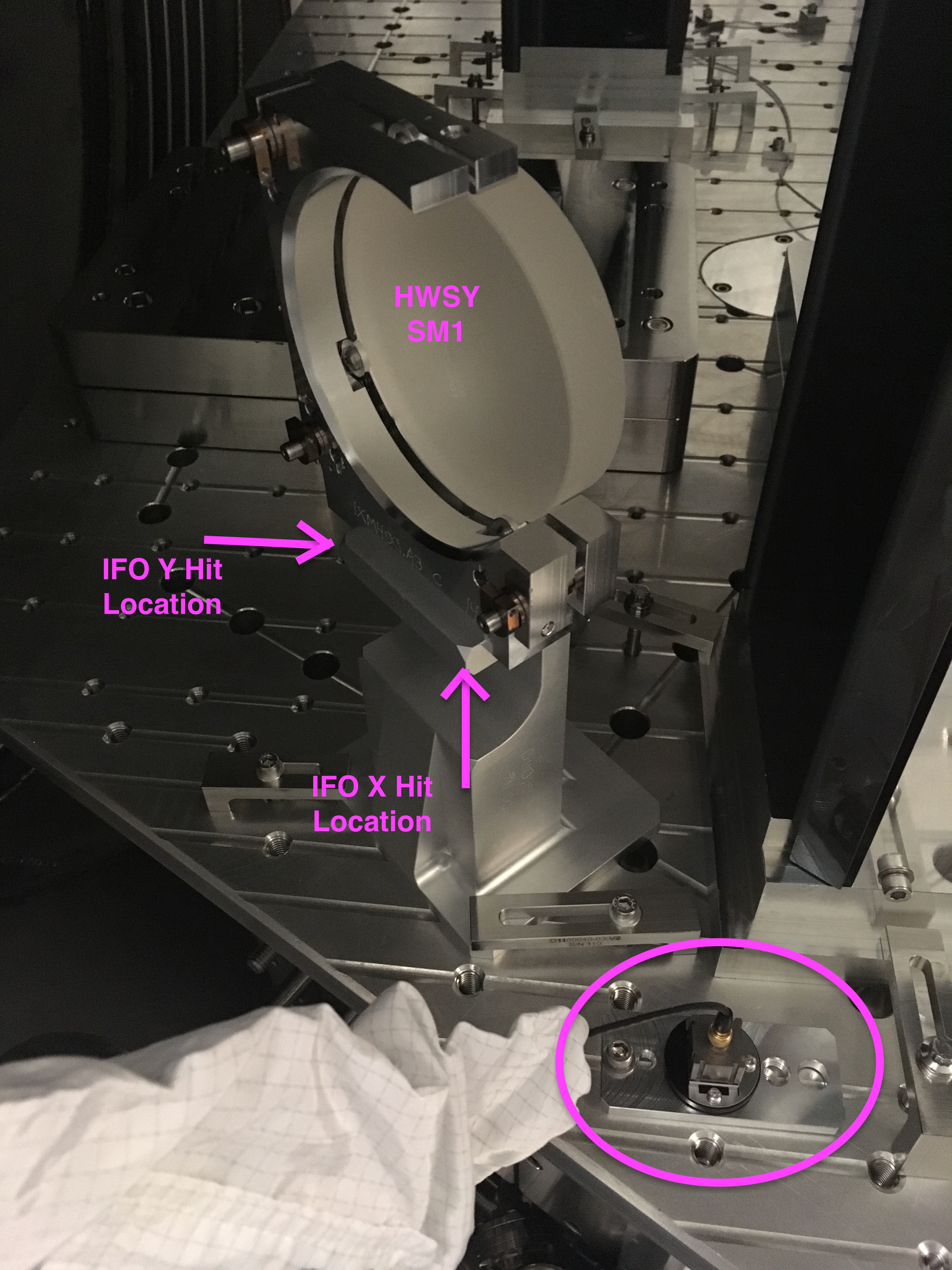
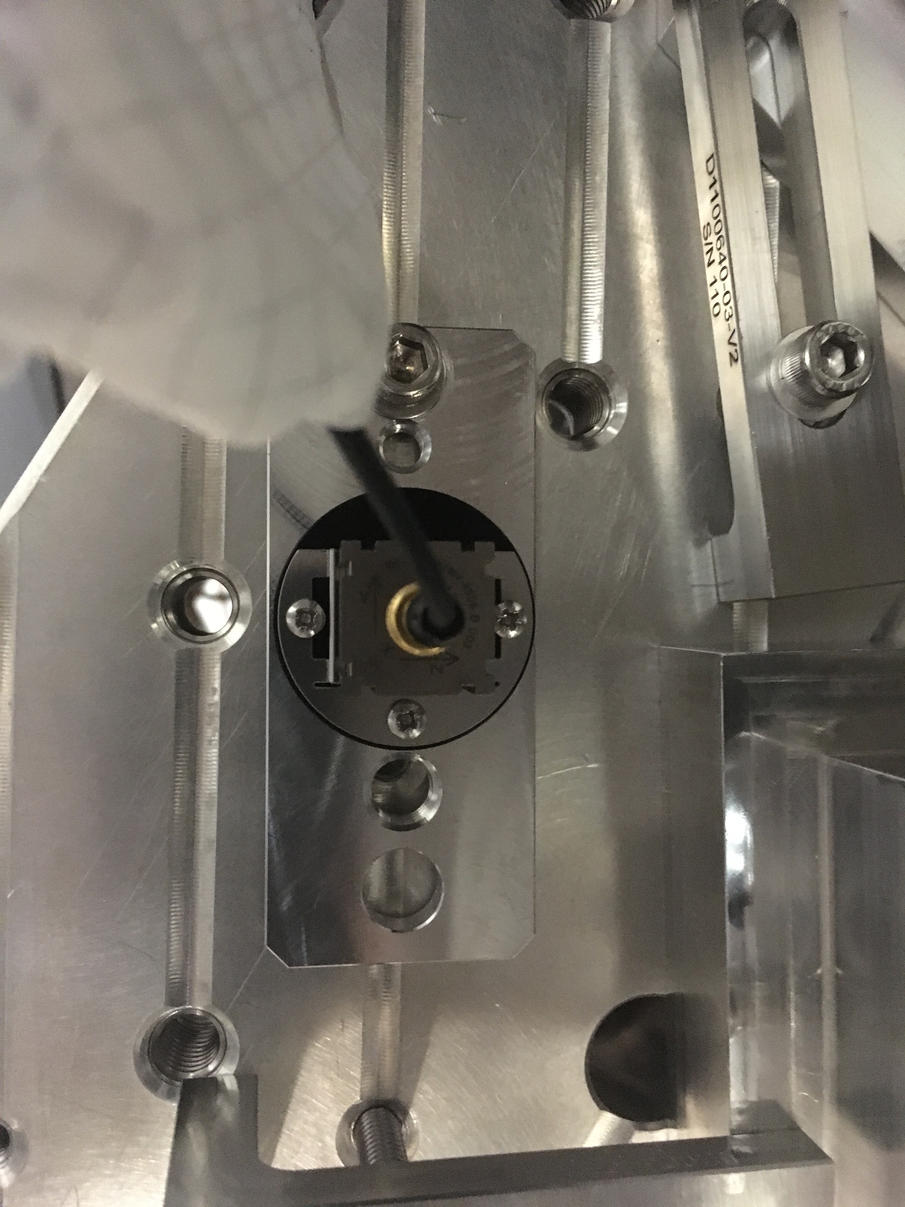
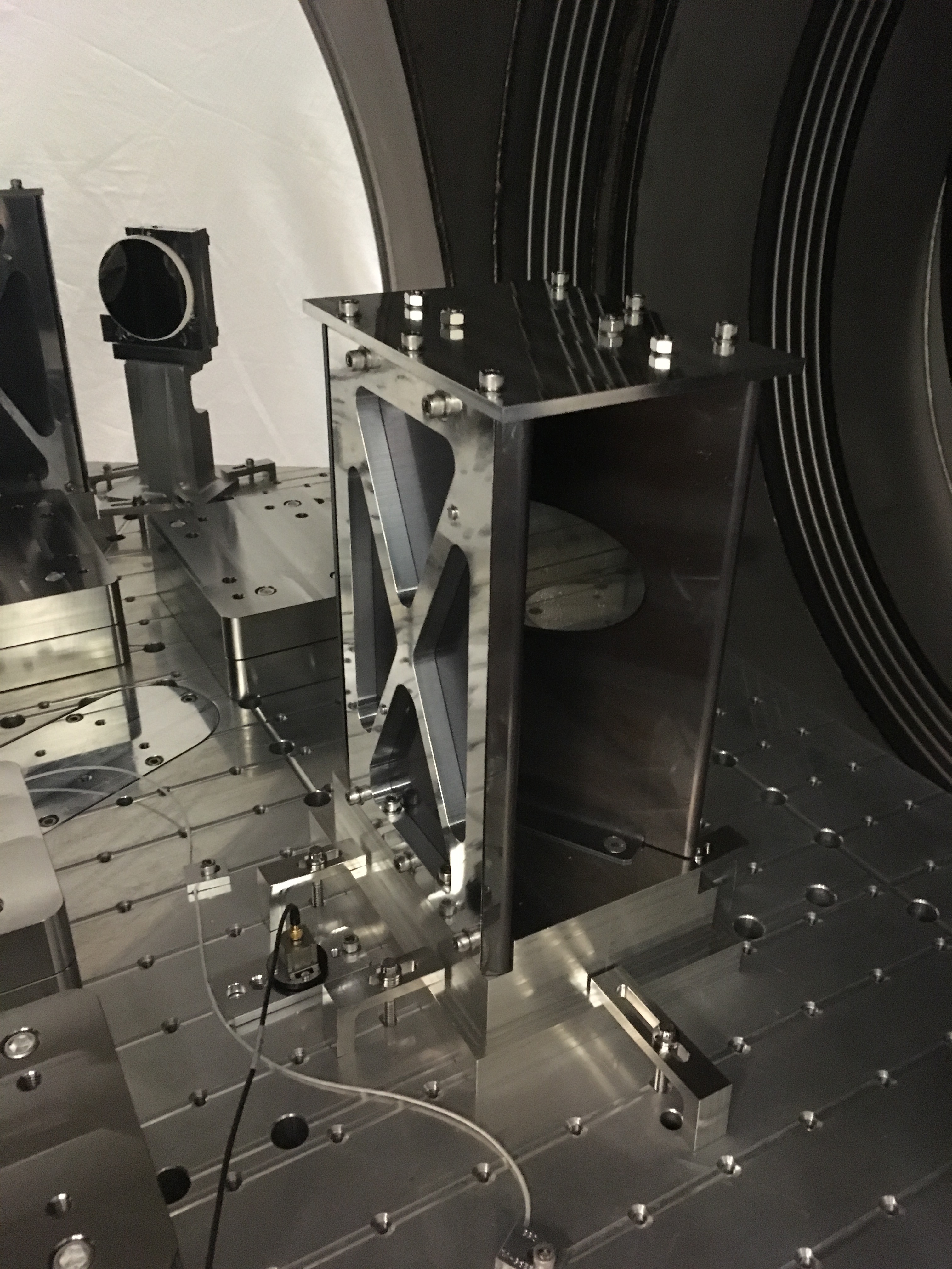
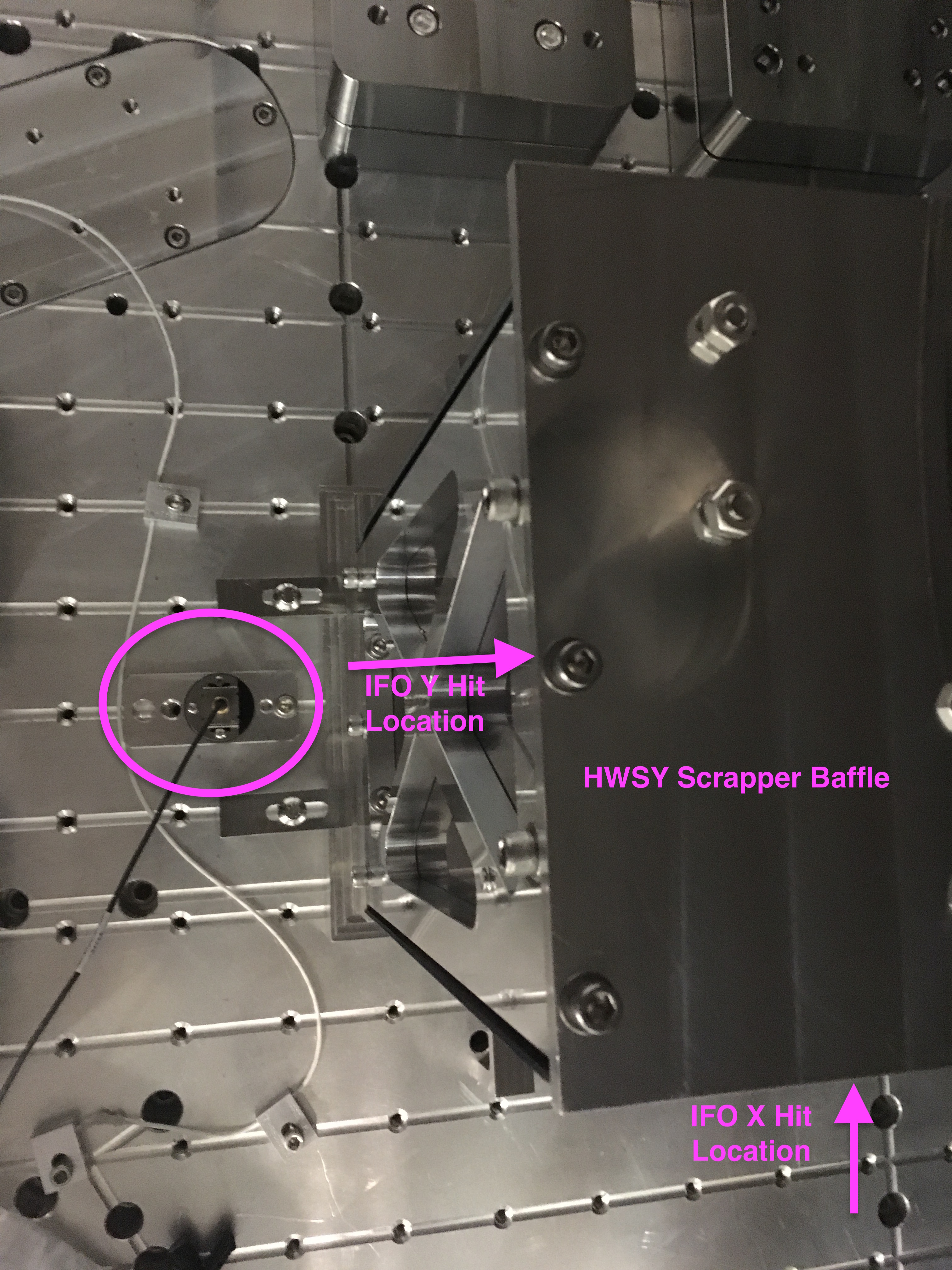
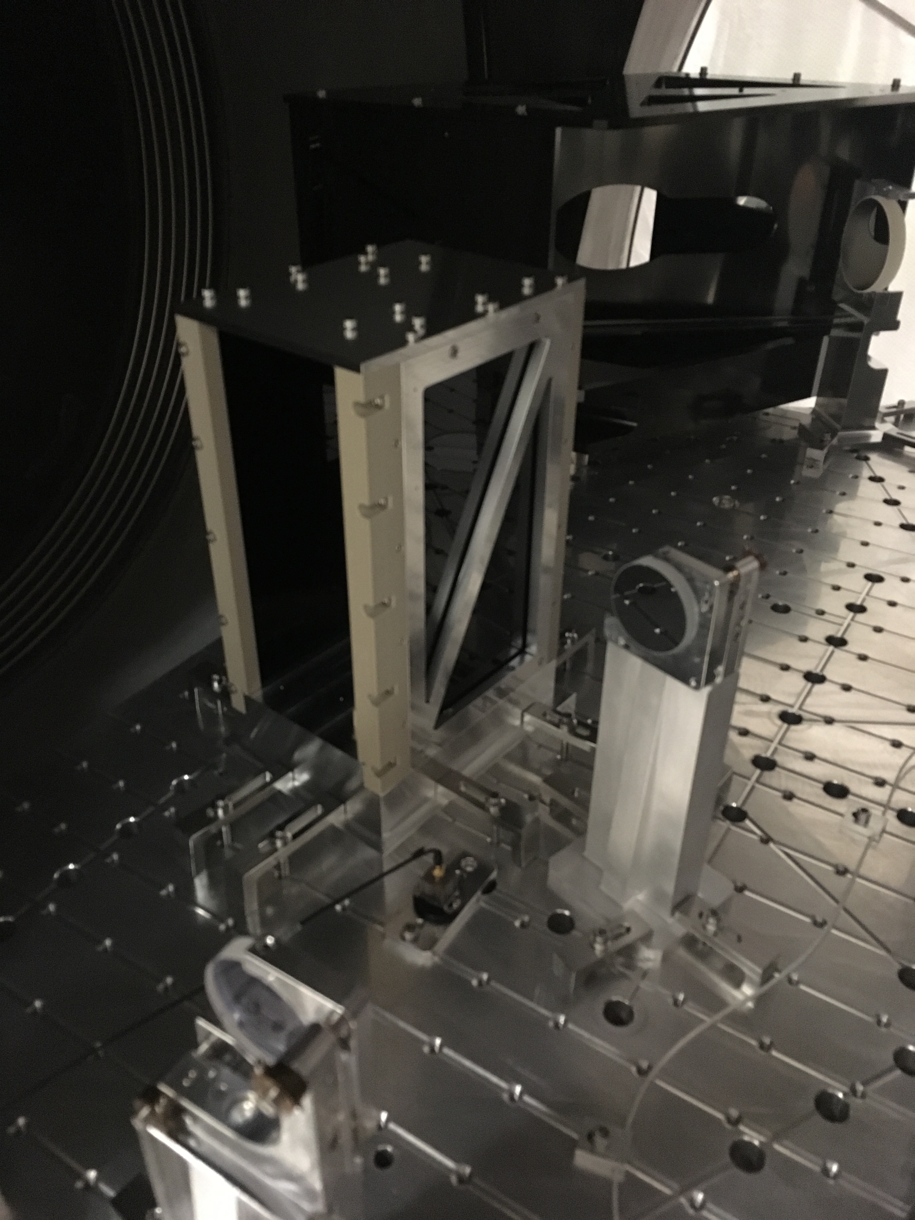
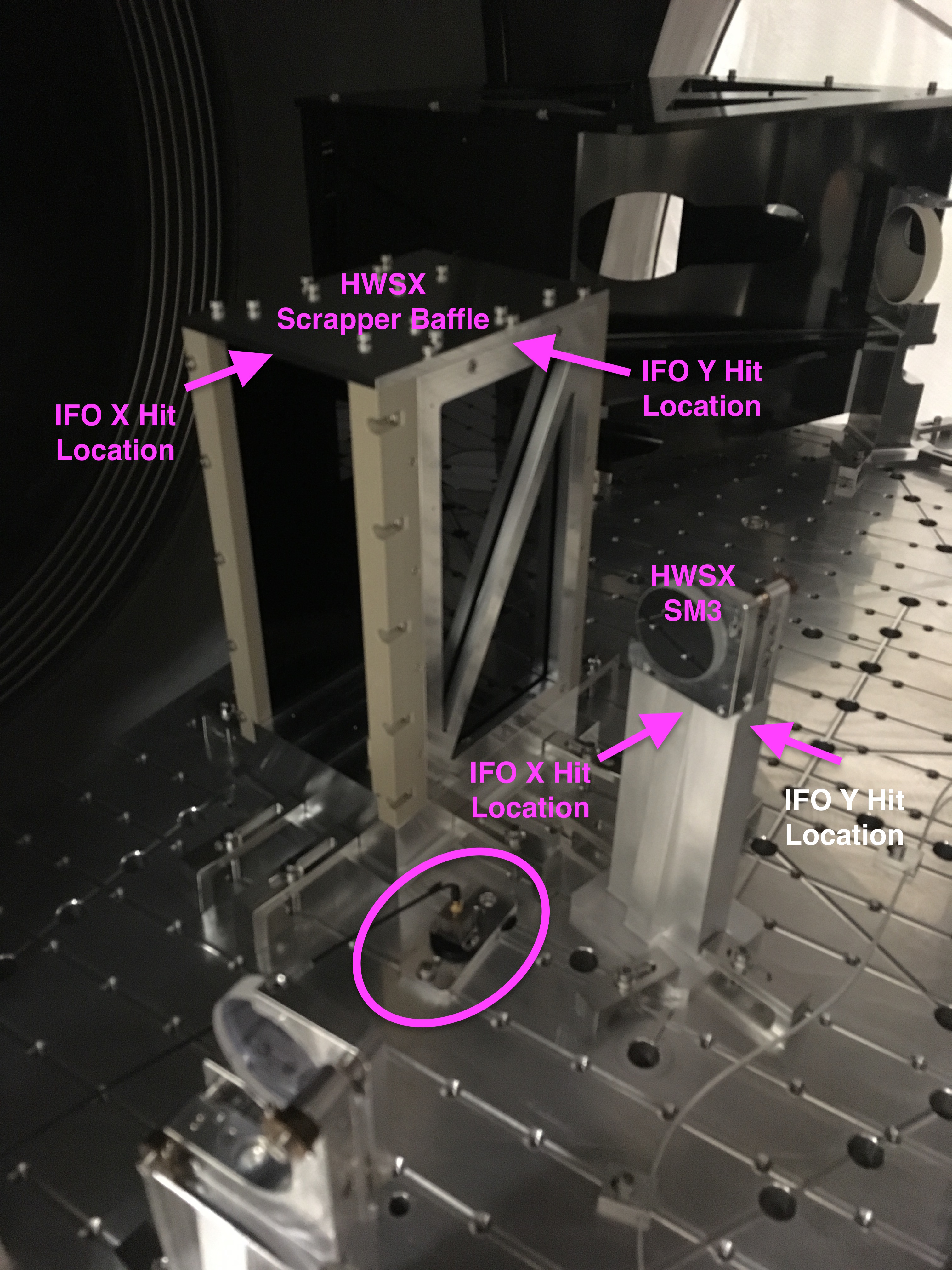
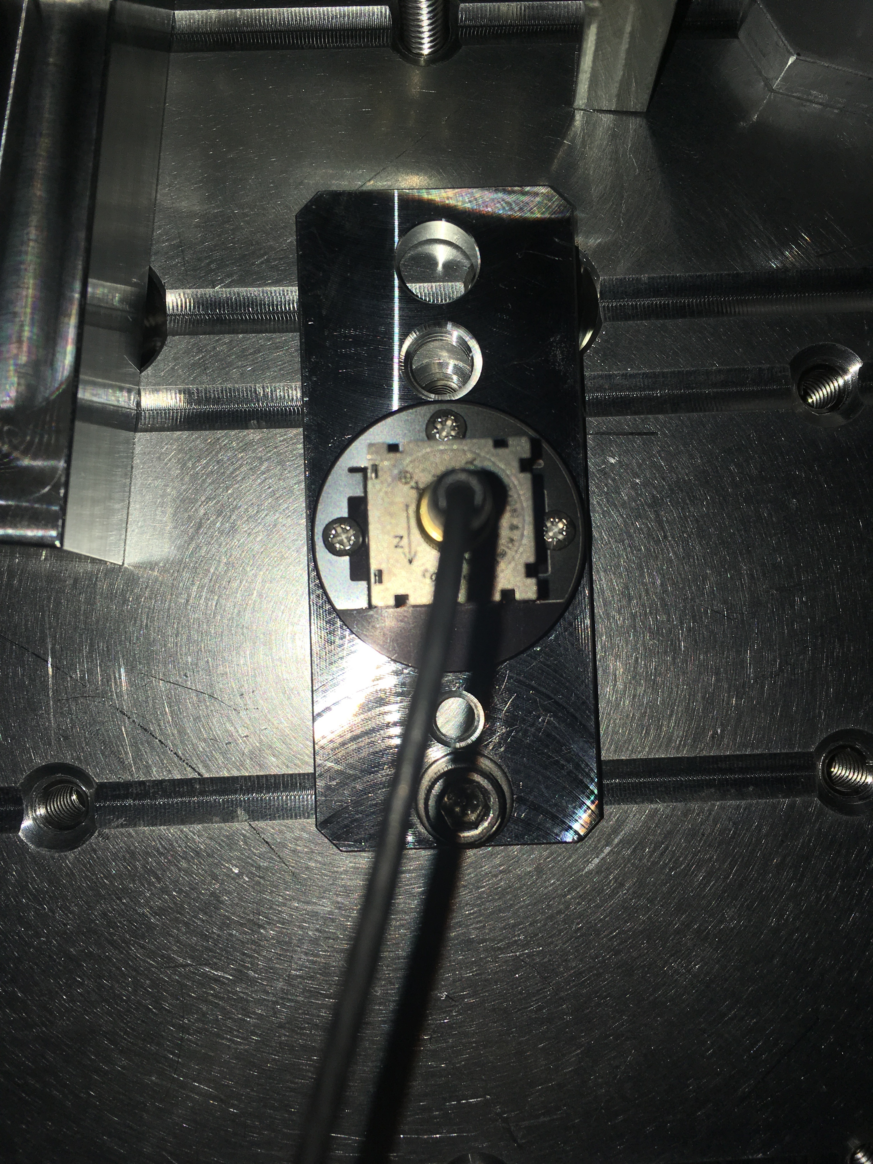
- 17:48 Jeff, Kentaro to Y beam manifold for camera work
- 17:52 Cheryl to LVEA to change PSL environment temp
- 18:16 Richard, Fil to LVEA to take pictures and measure
- 19:06 Koji to Optics Lab, OFI work
- 19:14 Bubba taking the film crew in the snorkel lift in the LVEA
- 20:50 Jeff B to EX,EY to check on dust monitor vacuum system
- 21:24 Terry to LVEA Squeezer Bay
- 21:25 Travis to LVEA to grab and pic equipment
- 21:30 Jeff B back
- 21:39 Patrick to EX
- 21:56 Purge air work complete, Hugh to HAM3 to balance
- 22:08 Patrick back, Jim to HAM3
- 22:43 Bubba and Mark to EY
- 22:44 Fil, Marc to LVEA to move some cables, they will need to use the roll up door for a few min.
- 22:50 Betsy to LVEA to clean up and prep parts
- 22:56 Keita and film crew to LVEA
- 23:58 Travis, Betsy out
- 23:59 Cheryl to PSL


FAMIS7464 closed.