travis.sadecki@LIGO.ORG - posted 14:18, Friday 20 October 2017 (39108)
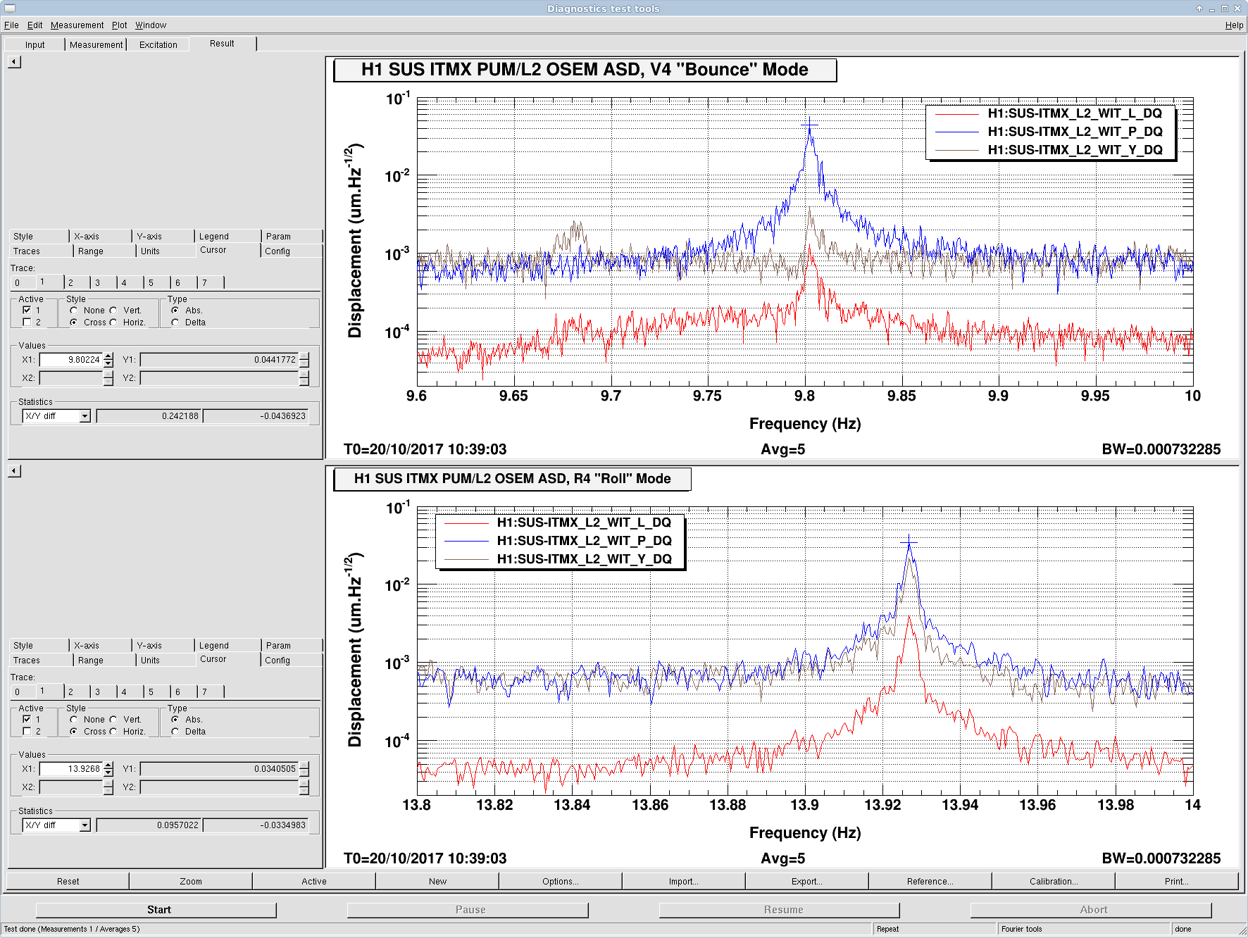
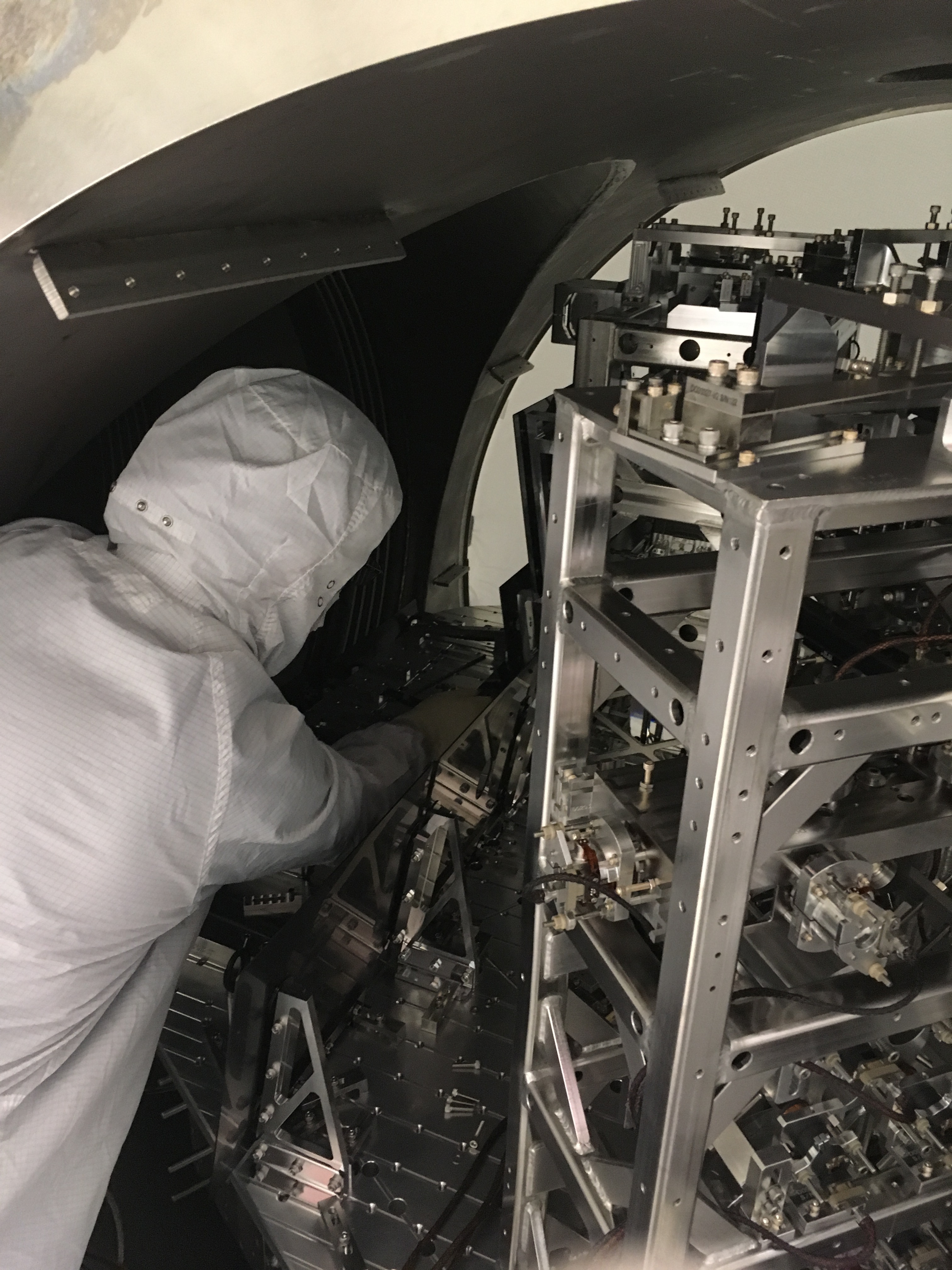
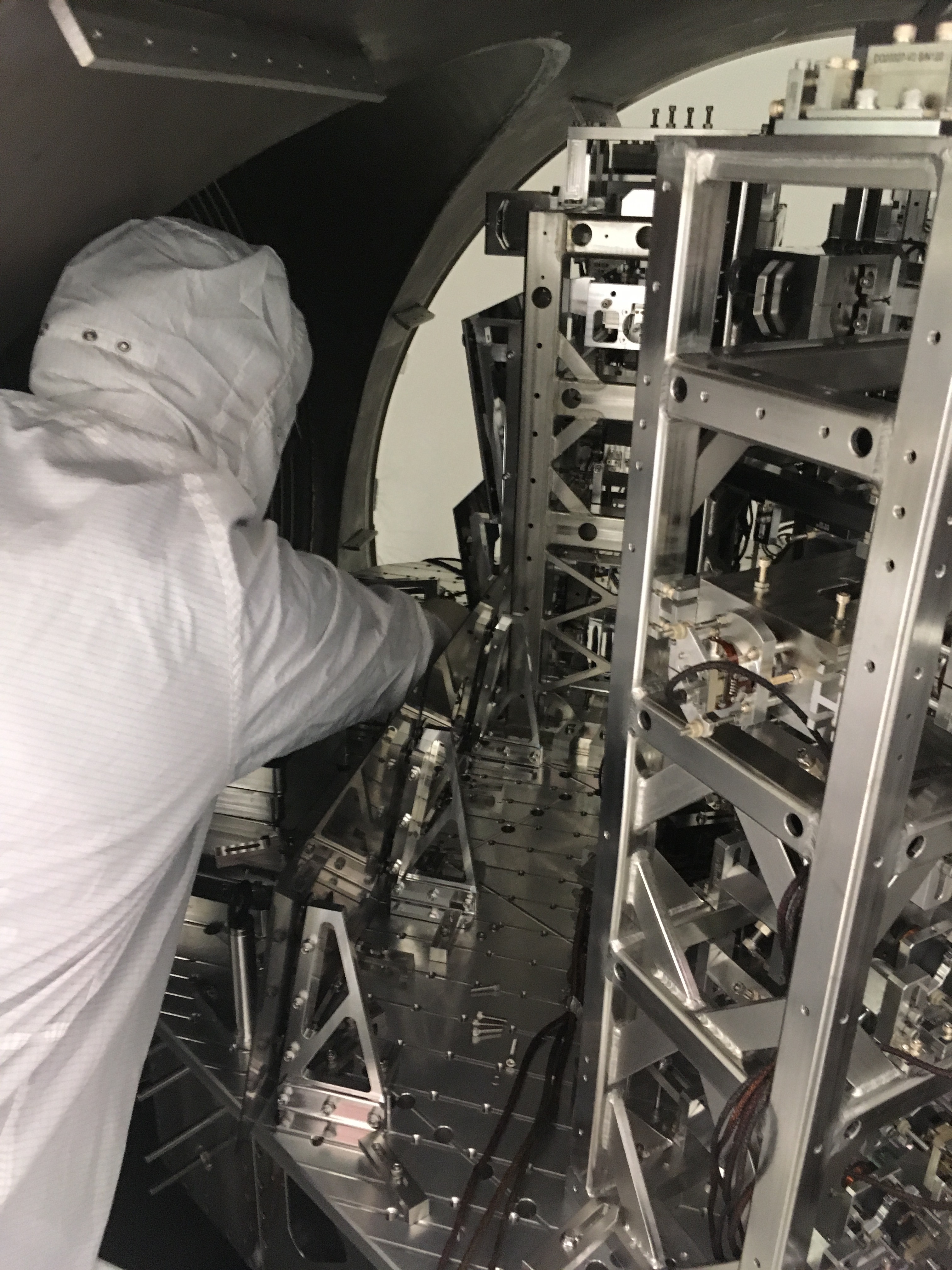
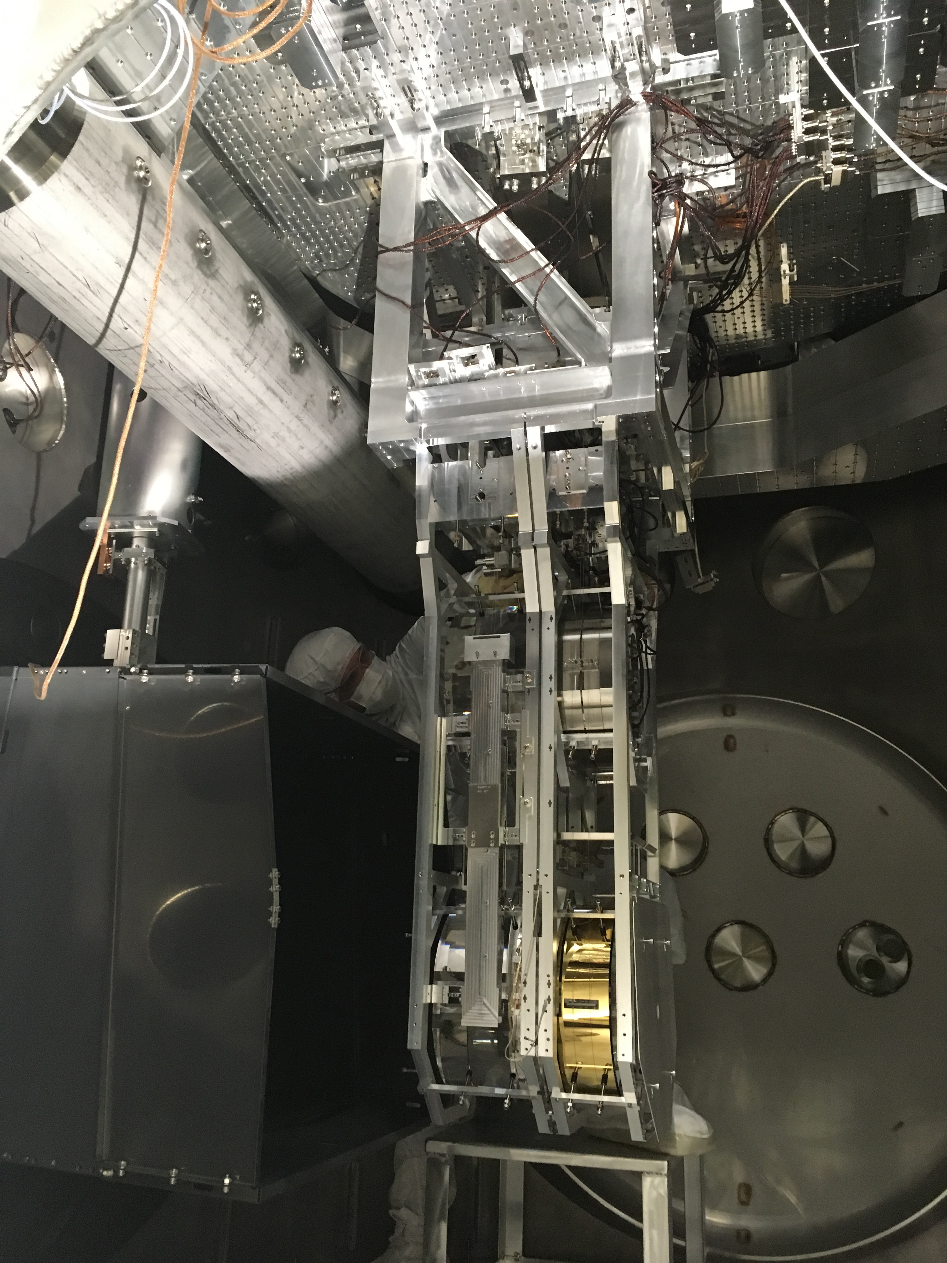
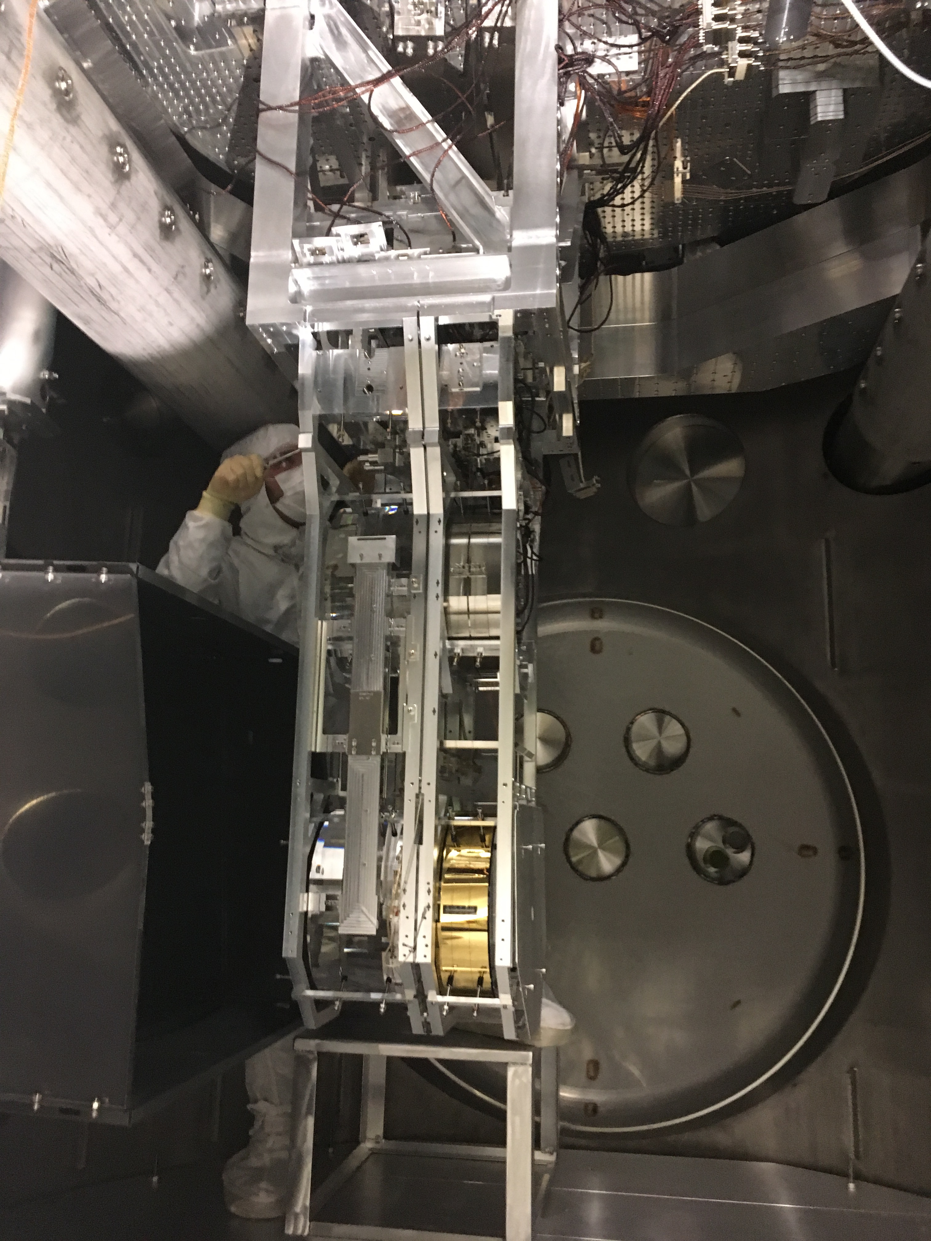
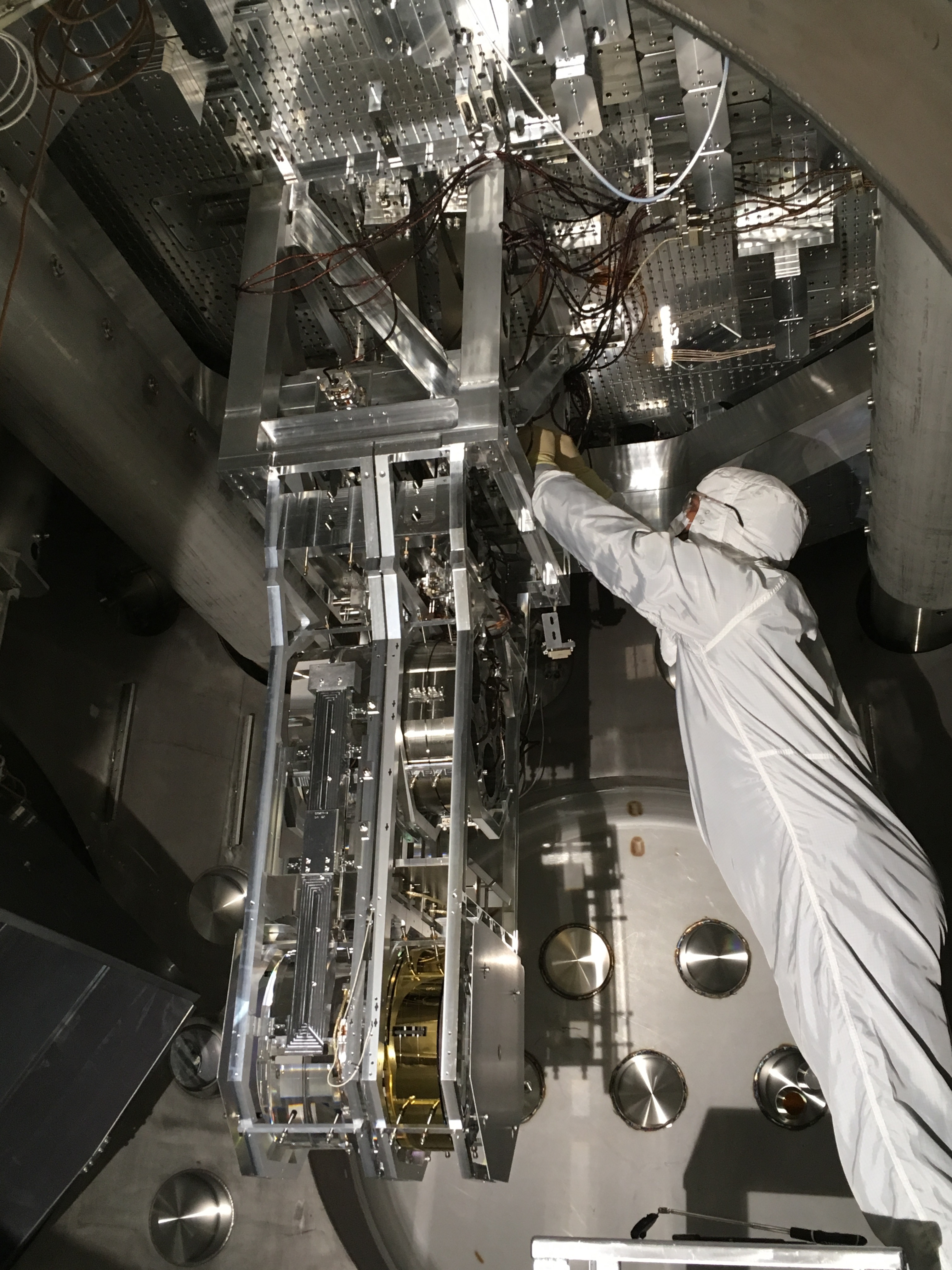
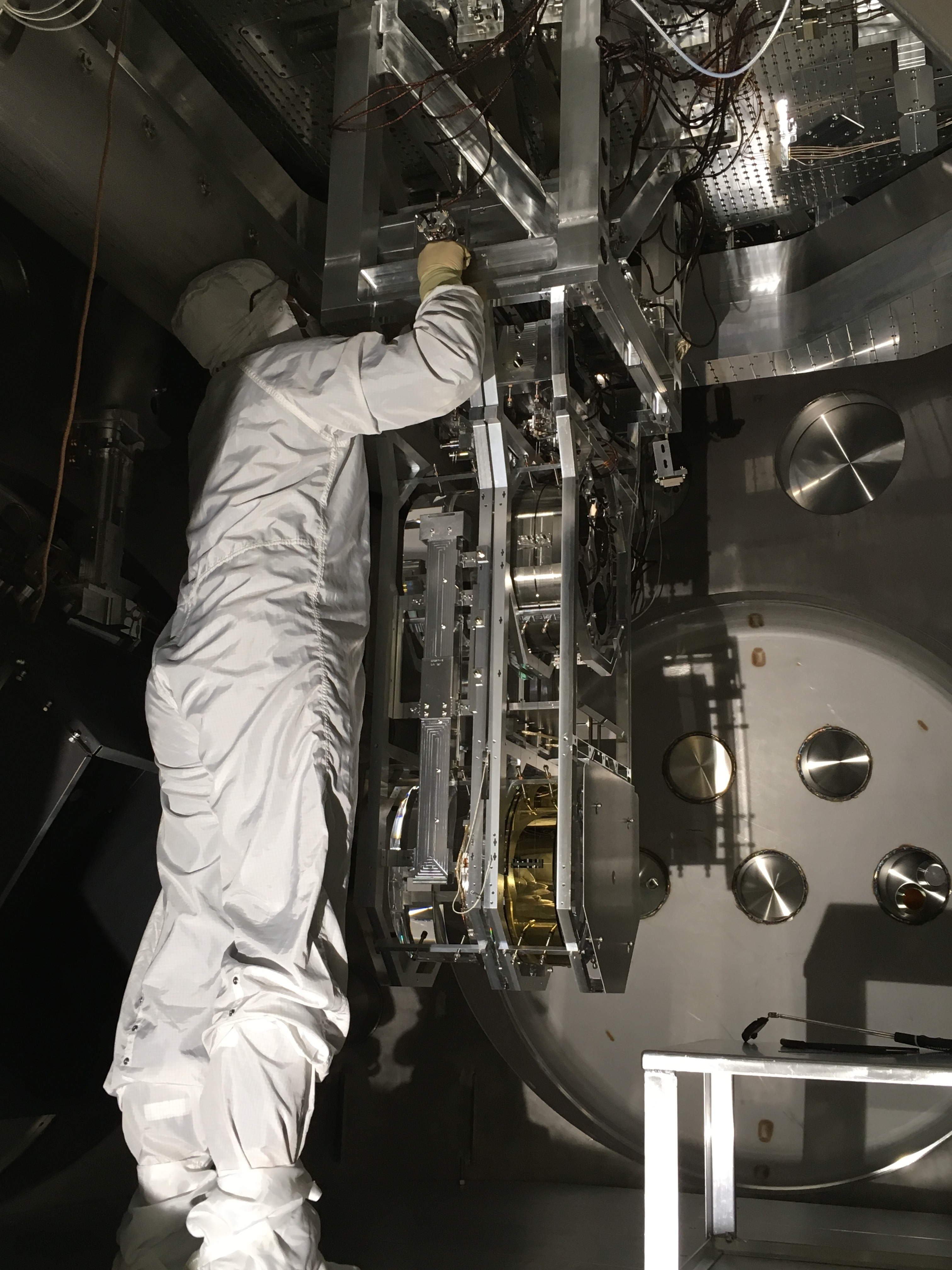
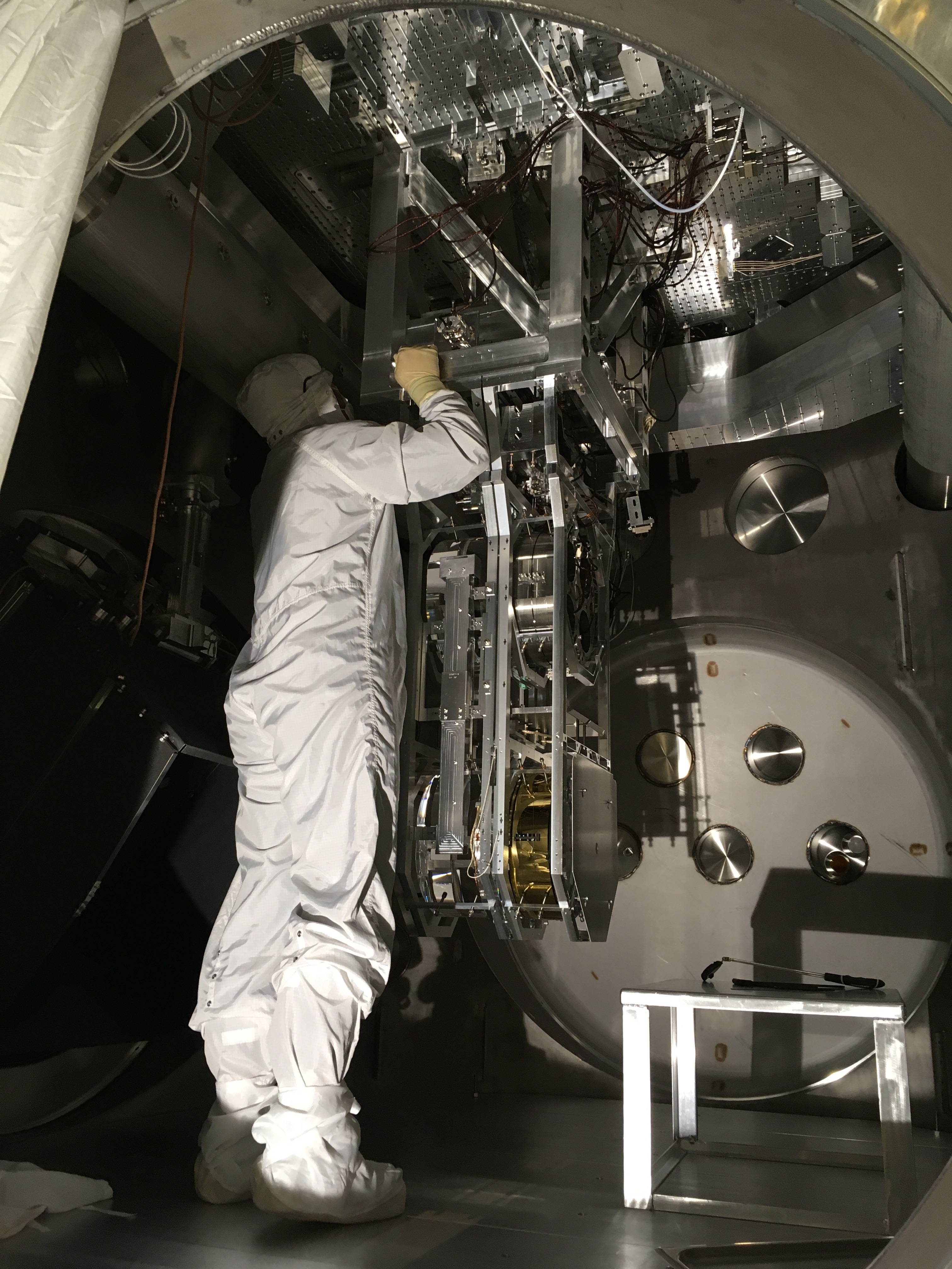
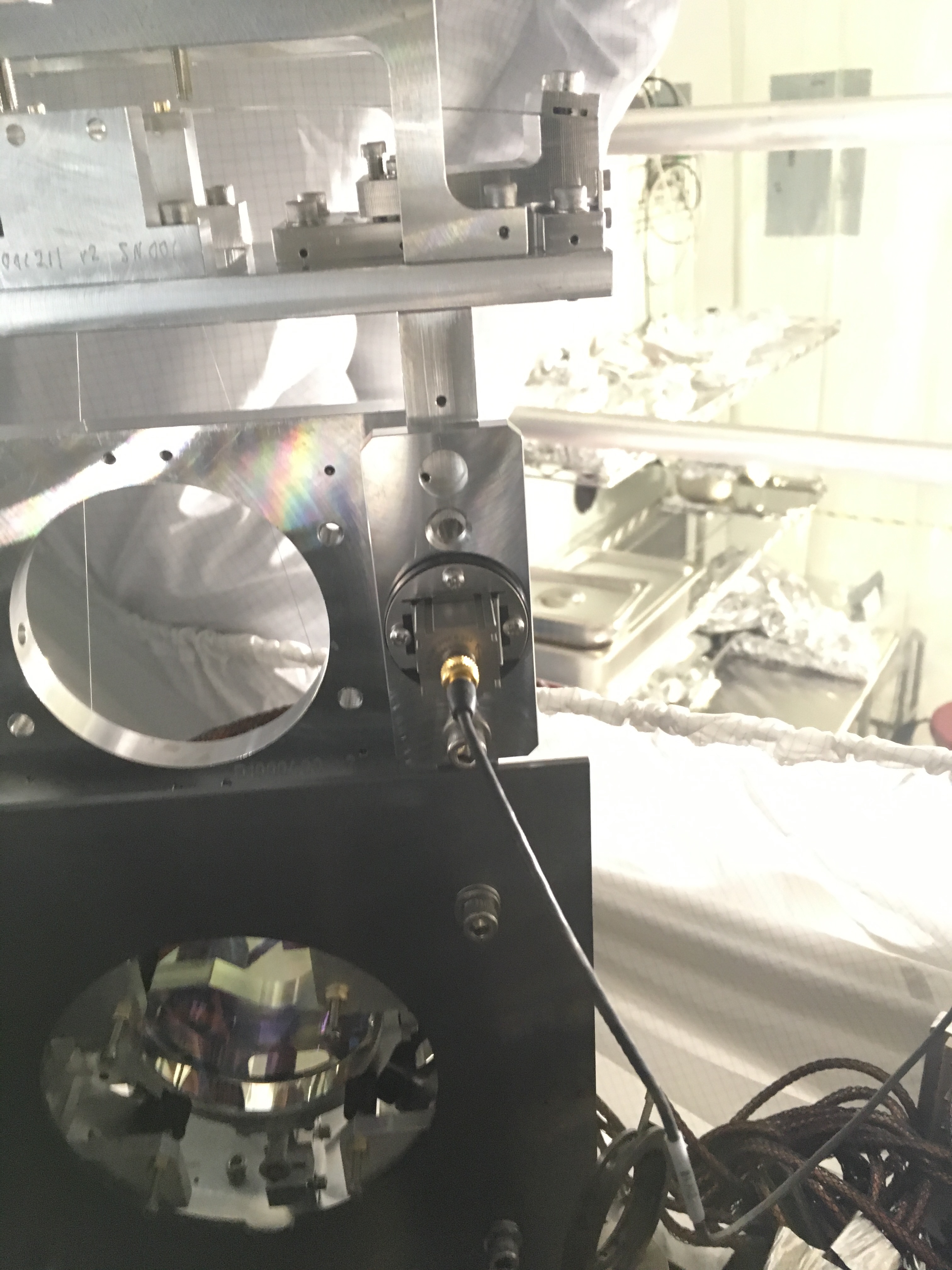
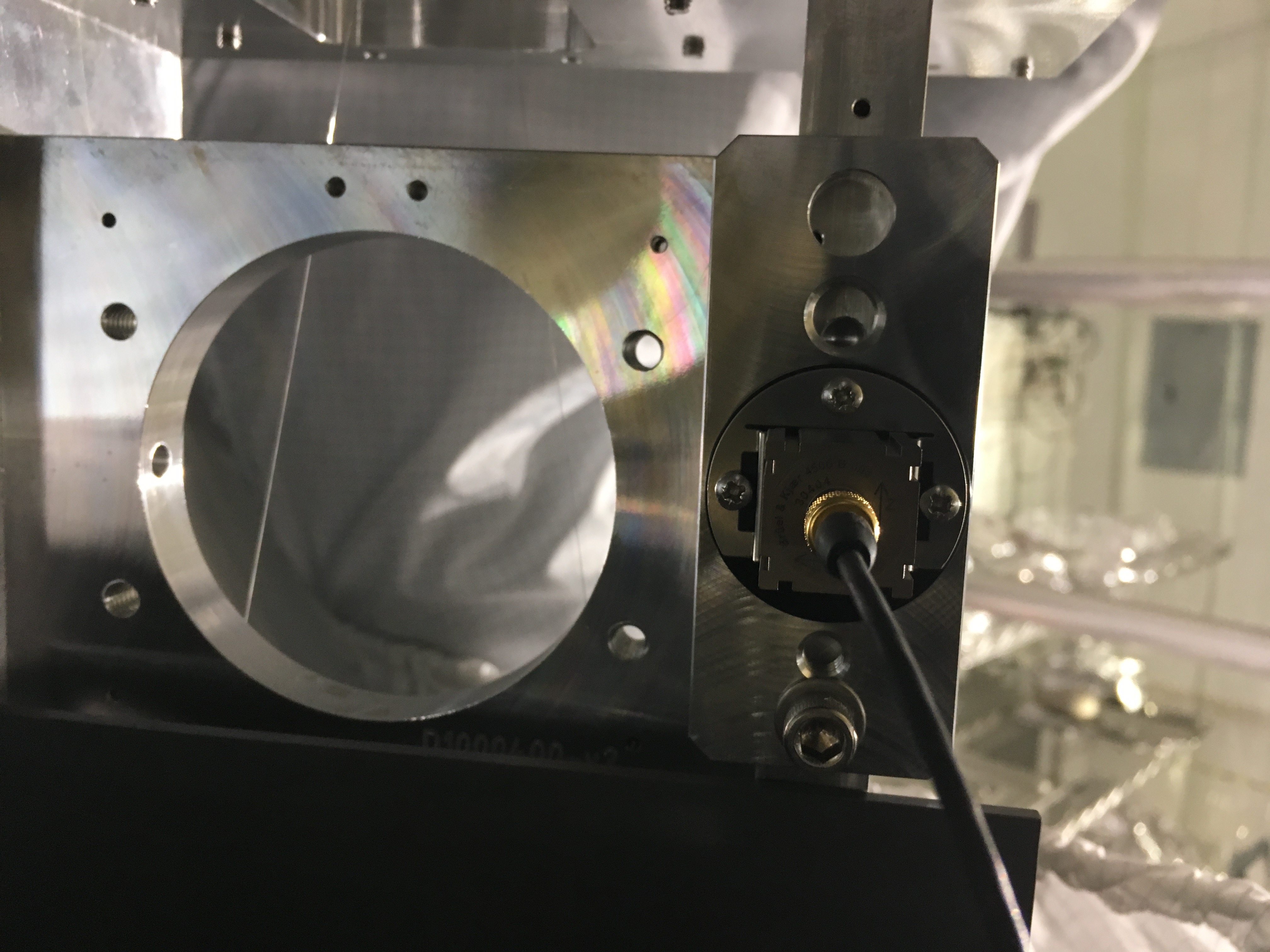
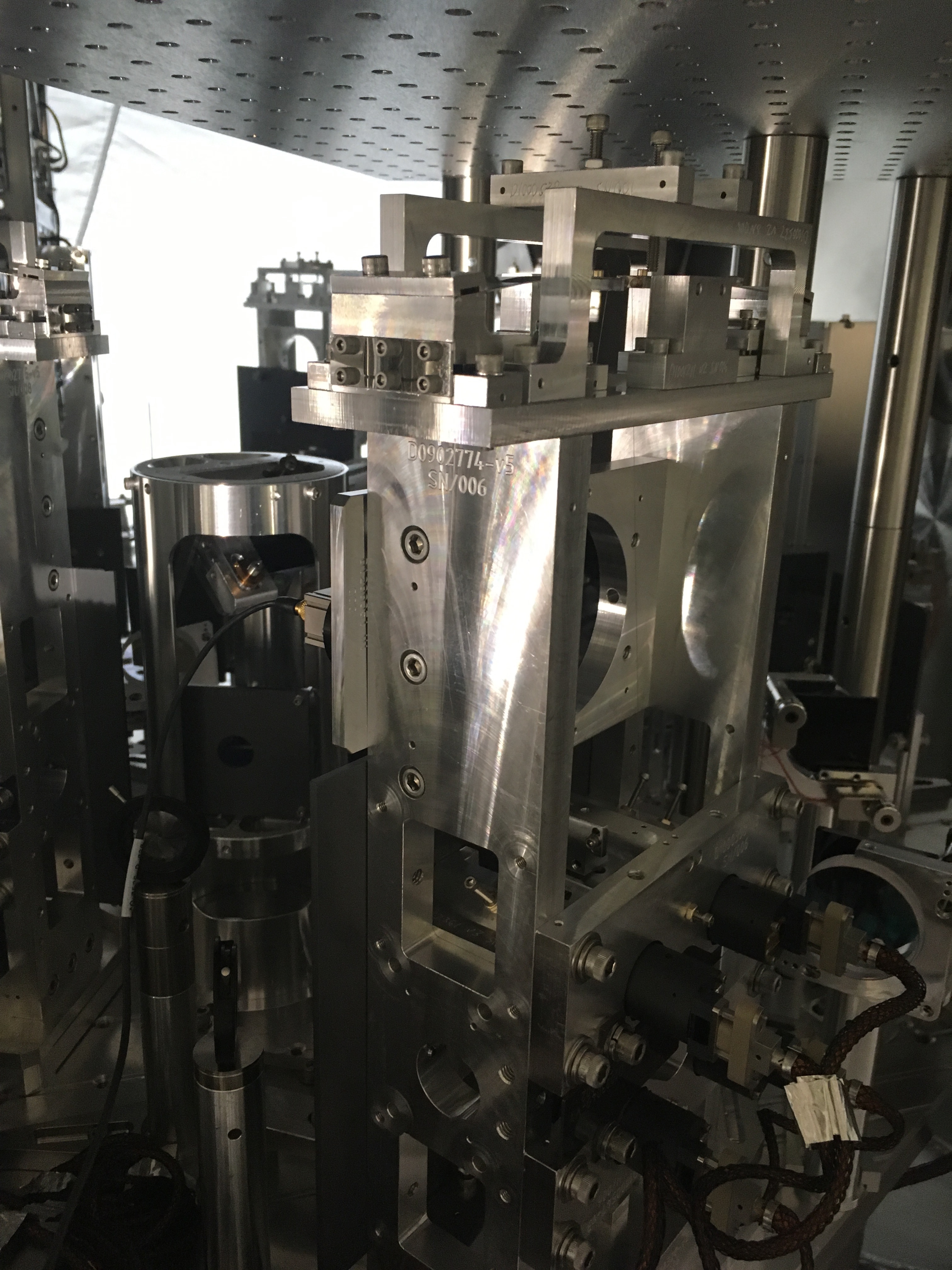
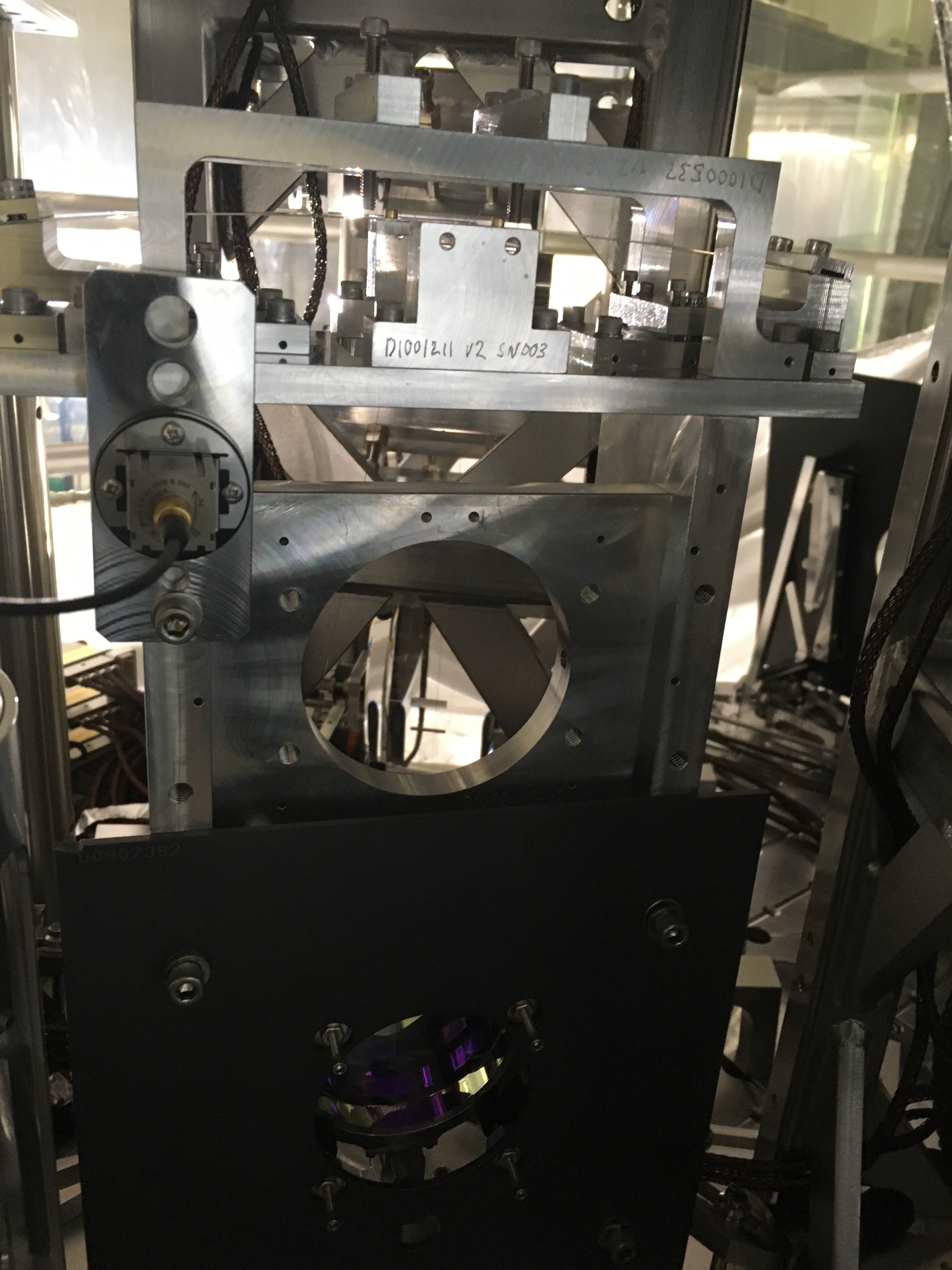
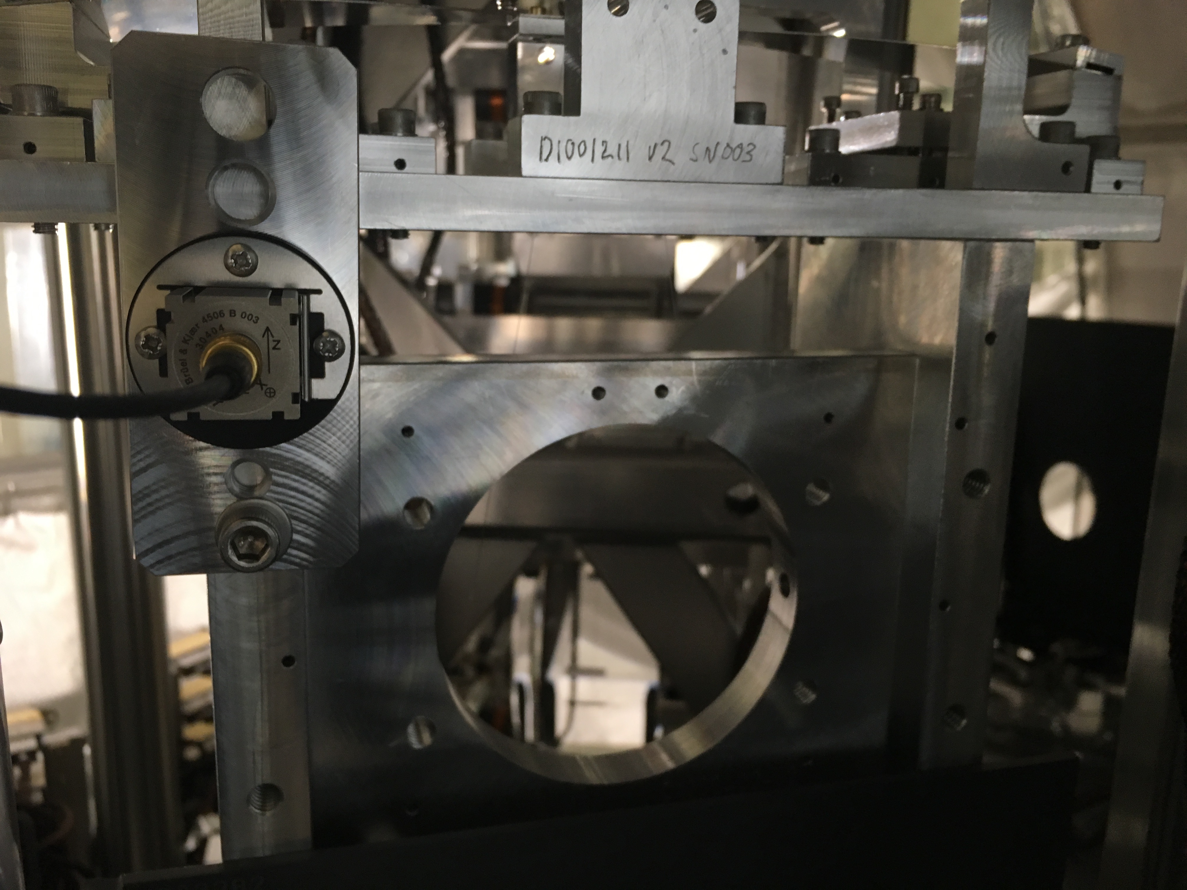
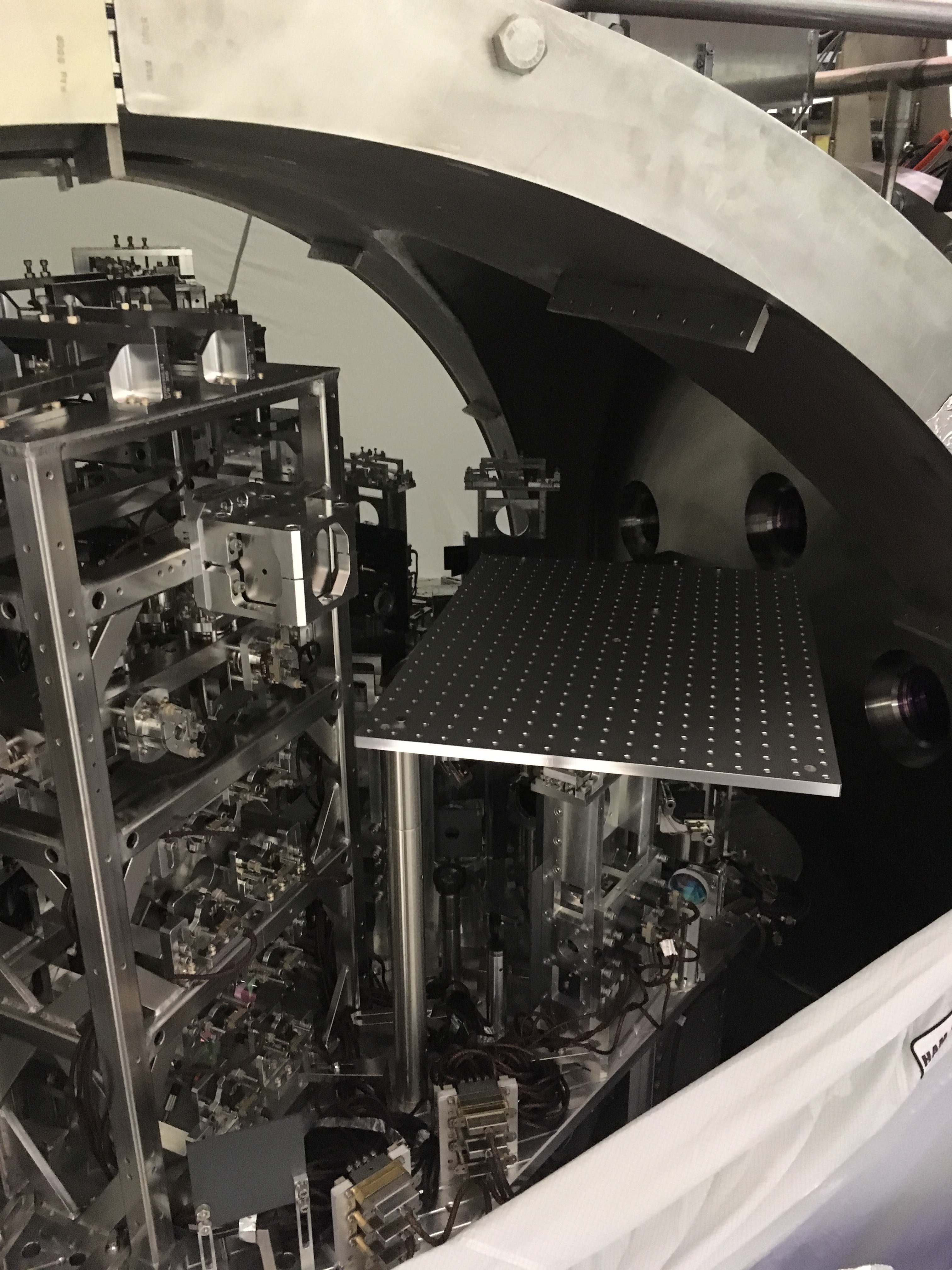
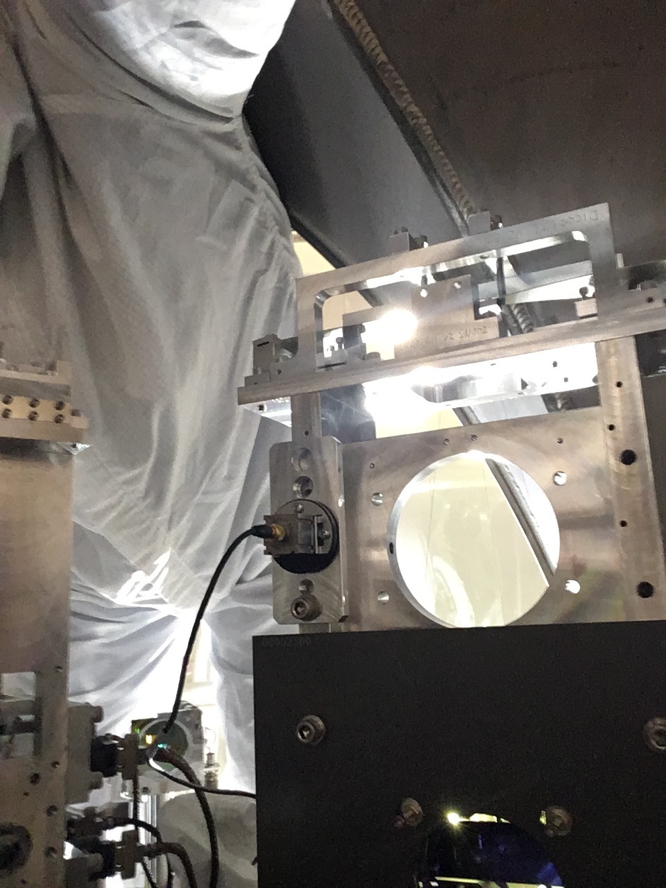
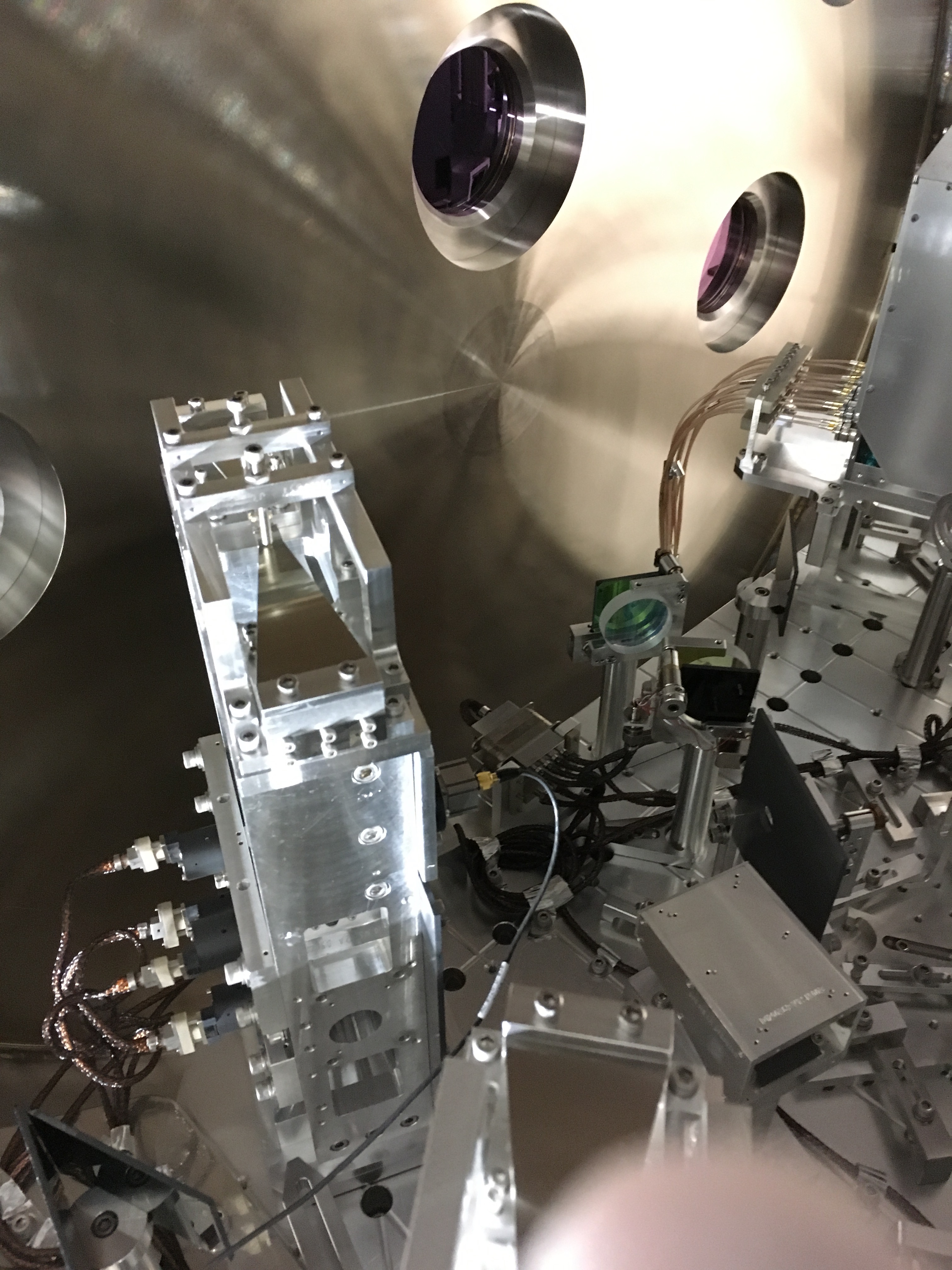
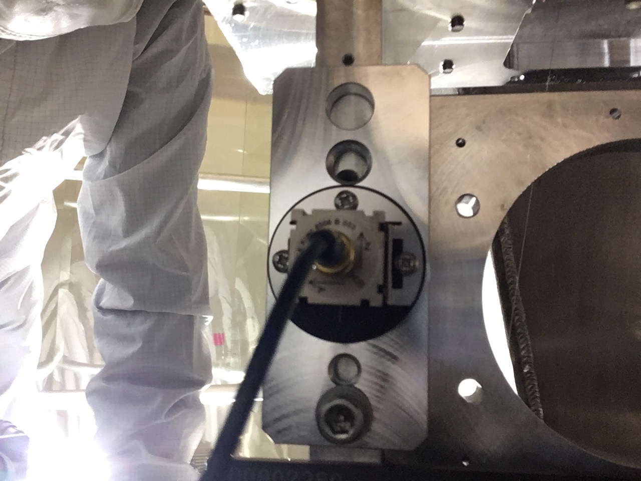
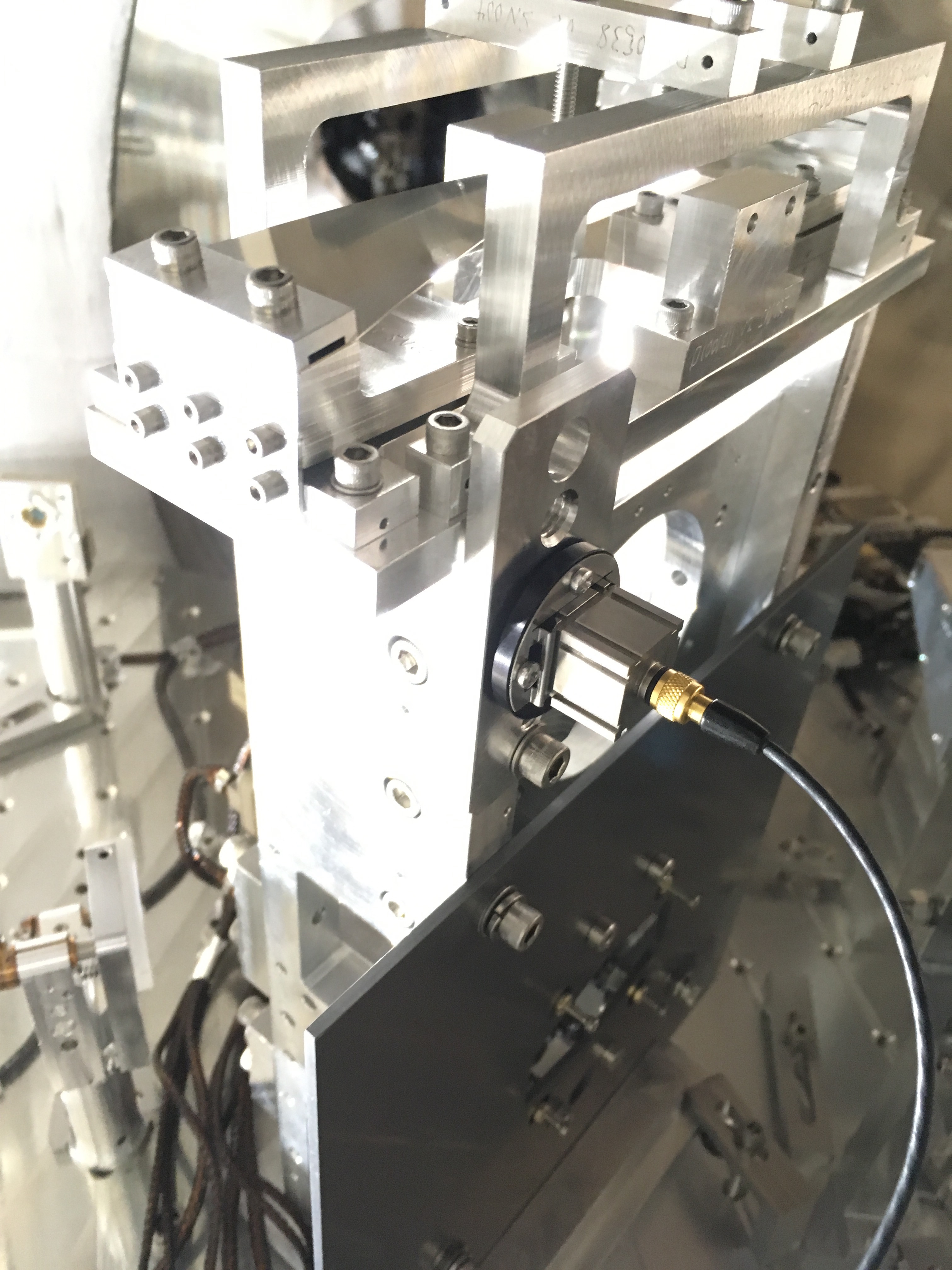
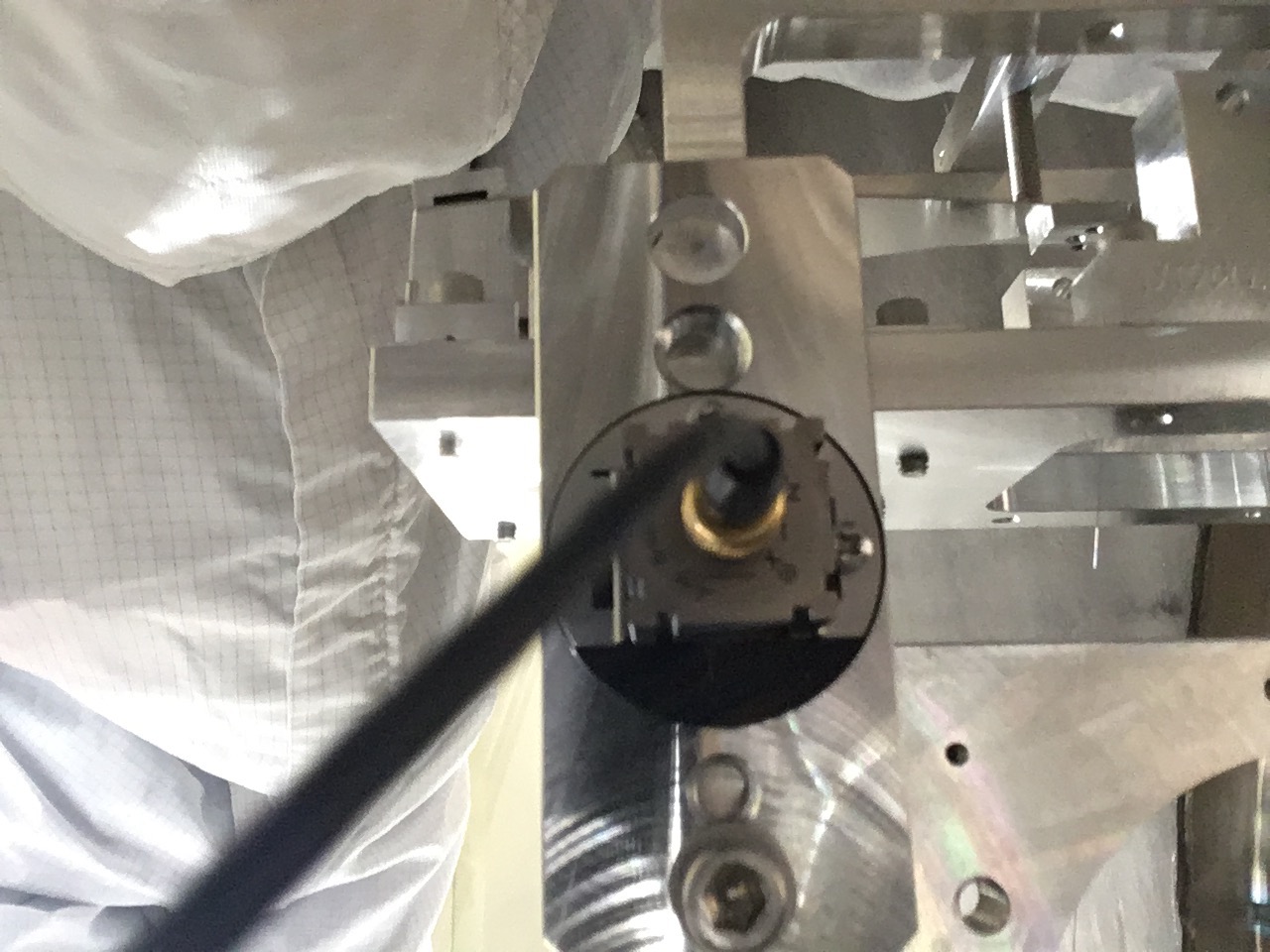
ITMx in-chamber violin mode measurement setup
J. Kissel, T. Sadecki
We setup the equipment in-chamber for measuring the fully suspended violin modes. We are currently setup on the +X/+Y fiber and a preliminary look at the spectra looks good. Jeff will proceed with getting the full set of data on Monday as he is going to run some health check TFs before proceeding further.