1. Matching the gain of each quadrant:
When we reached DRMI locked last night, we adjusted the gain of each AS72 WFS quadrant s.t. the 205 Hz line after the first demod all having roughly the same amplitude.
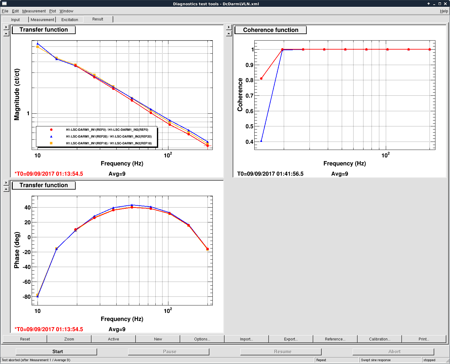
2. Adjusting the phase:
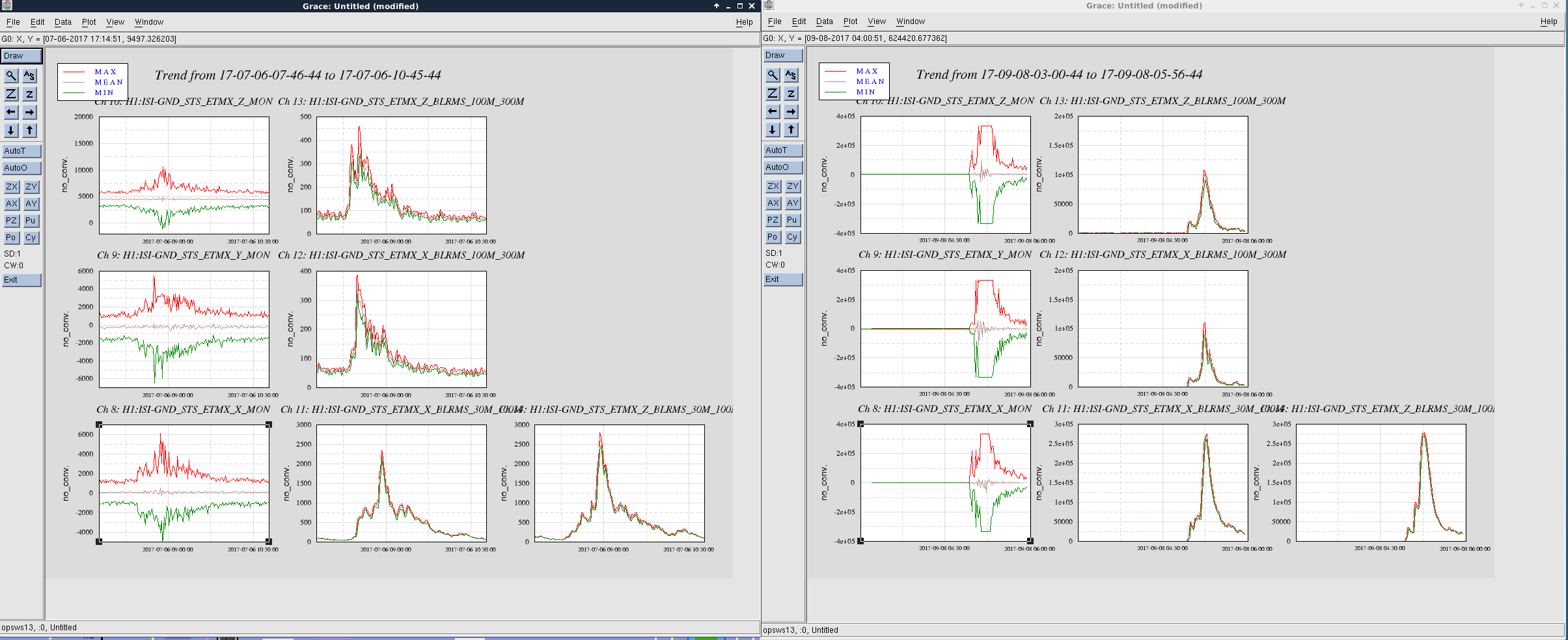
We drove SRM in length at 4Hz last night from 04:40:00 to 04:47:00, Sep 08, 2017 (UTC). Then offline we computed the transfer function from AS_AorB_RF72_I1_DEMOD_I to AS_AorB_RF72_Ij_DEMOD_I at 4Hz. Each quadrant's phase is then adjusted to compensate for the tf phase. For future reference, the tf phase were:
Relative phase for AS72 WFSs
| |
seg 1 |
seg 2 |
seg 3 |
seg 4 |
| A |
0 |
8.6 |
-4.1 |
-15.0 |
| B |
0 |
3.8 |
7.6 |
4.3 |
3. 118MHz mod depth measurement:
We also use the driven line to measure 118MHz SB's mod depth relative to 9MHz.
| |
optical gain |
PD resp. |
whitening |
anti-whitening |
filter gain |
final resp in cnts/rtHz @ 4Hz |
| AS36 |
gamma_9 |
-12dB |
12dB |
-12dB |
2.8 |
132 |
| AS72 |
0.5*10*gamma_118 |
-24dB |
45dB |
-24dB |
1. |
0.42 |
where in the opt. gain, the 0.5 accounts for that the AS72 has one more demod (half of the signal lost at 2xf_dmd), 10 for 118MHz DRMI transmission relative to 9MH (assuming dithering SRM in length only changes 45MHz and 9/118 serves as a static reference field); the PD resp was from T1300488; the final cnts had a bw of 1/256 sec.
We thus have gamma_9/gamma_118 ~ 1, 600, consistent with what Kiwamu measured in 37061.