cheryl.vorvick@LIGO.ORG - posted 09:01, Friday 01 September 2017 (38478)
Ops Day Transition:
- H1 unlocked
- ran Initial Alignment
- ThomasV has X arm locked in red for absorption measurements
We preform more FINESSE simulations on the AS72 scheme, focusing on how the signal changes when we switch to the new SRM (T_srm=0.37 -> 0.32), and possible solutions if we are sitting on the ill-conditioned regions.
Conclusions:
1. If the AS72 sensing matrix measured now (with differential wavefront distortion; T_srm=0.37) behaves well, the sensing should be fine after we replace the SRM.
2. If the sensing matrix for AS72 is close to being degenerate, after replacing the SRM the sensing is likely to be even worse.
In case that the sensing matrix is bad (e.g. we are sitting at AS port gouy phase 45-75 deg in the plots), possible solutions:
i. Increase the SRC one-way gouy phase to ~20 deg (e.g. with SR3 ring heater; current nominal SRC gouy phase is ~18 deg). This should be the BEST solution. For more details, please see 37222.
ii. Use ASA_72Q and ASB_36Q for SRM/BS sensing. This scheme work only for a very narrow (AS port gouy phase + diff lens) space.
iii. Use ASA_72Q and (ASA_72I - ff x ASA_DCQPD) where the ff is set to decouple the spot centering. This should cover the AS port gouy phase space corresponding to 45-70 deg in the plots.
Sheila, Jeff, Corey, TVo
After opening the gate valve at ETMX, we started locking to measure the charge in-lock using Sheila's script in aLOG-38387
However, we had trouble getting past the CARM_10PM state and Sheila noticed that the alignment might be bad because of the ratio of REFL power locked to unlocked was too low and the PRC Gain was lower than normal as well. Even after running initial alignment twice, the same problem still persisted so we're thinking there may be some extra absorption in the arm cavities, we will follow up tomorrow.
For the record, Sheila referenced LHO aLOG 36439 that documents symptoms of poor alignment during the CARM reduction causing lock losses. However, after several initial alignment attempts, and some by-hand tuning of the alignment, the power recycling gain did not improve; hence this investigation into arm losses.
Jonathan, Dave:
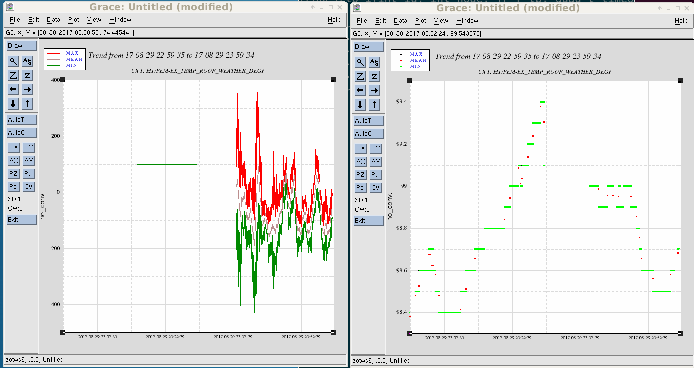
we were reminded this week of a second trend NDS1 issue if the user asks for data which spans a DAQ restart. NDS1 has an optimization turned on which reads the channel list from the first second trend frame file in the time sequence and applies it to all subsequent files. It looks for a missing file as an indicator the DAQ was restarted and the channel list needs to be re-read. This worked when second trend frame files were one minute in length, but does not work when they were extended to ten minutes in length.
The temporary solution is that I will rename the partial second trend frame file by pre-pending a dot (ditto with its associated md5 file) after I have ascertained that LDAS has archived the file.
The attached dataviewer one hour second trend plots of the EX building outside temperature spanning yesterday's DAQ restart show a before and after this fix was applied. Before the fix the temperature went from 99F to +/-400F, after the fix the correct temperature is shown with a 10 minute data gap.
The long term fix is to use the run-number in the frame header as a channel configuration index.
TITLE: 08/31 Day Shift: 15:00-23:00 UTC (08:00-16:00 PST), all times posted in UTC
STATE of H1: Commissioning
INCOMING OPERATOR: None
SHIFT SUMMARY:
First part of the day was devoted to opening the EX gate valve & then making attempts at locking. So far, for locking we have been dropping out at the CARM_5PM step.
NOTE: Tomorrow morning Kyle would like to enter the end stations to transfer TMDS equipment from EX to EY (this is for discharging ETMy on Tuesday Mainteance).
LOG:
This completes WP #7119 and WP# 7134.

PT525 finally "woke up" when, by opening GV20, the X-end pressure changed by a factor of x10.  We have noted in the past how the new-to-us Bayard-Alpert/parani wide-range gauges differ from our traditional Cold Cathode gauges, both in magnitude and general behavior.  This difference is greater as the real pressure increases.  The Parani portion of the new gauges agree well with our traditional convection enhanced paranis but in the HV pressure ranges they are just "different".  We know that the CC gauges pump with about 1 or 2 l/s pump speed while the nude BAs don't pump.  For the conductance due to our arrangement of fittings, this can explain a difference between the two gauge technologies of up to 50% but not factors of 3, 5 and 10!

The newest odd behavior shows up as a complete "lock up" of the gauge.  It gives valid but non-changing output in the example shown recently at the X-end (see attached graphs)


Note:  In WP #7134, I mistakenly indicated that I was leaving the 1.5" valve which isolates GV20's gate annulus from the rest of the annulus piping "open" after opening GV20 and that this was a policy change.  In fact, I am leaving this 1.5" valve "closed", as is standard policy when the 44" gate is open.  I believe that the new, "Chandra era", change in practice applies only to when the 44" gate is closed for prolonged periods.  For this case, we will now be leaving the 1.5" open so as to eliminate the need to "dump" the un-pumped gate annulus volume into a temporarily connected aux. pump cart.
We should also get in the habit of tagging the GV controller to remind us to close the right angle valve before opening the GV.
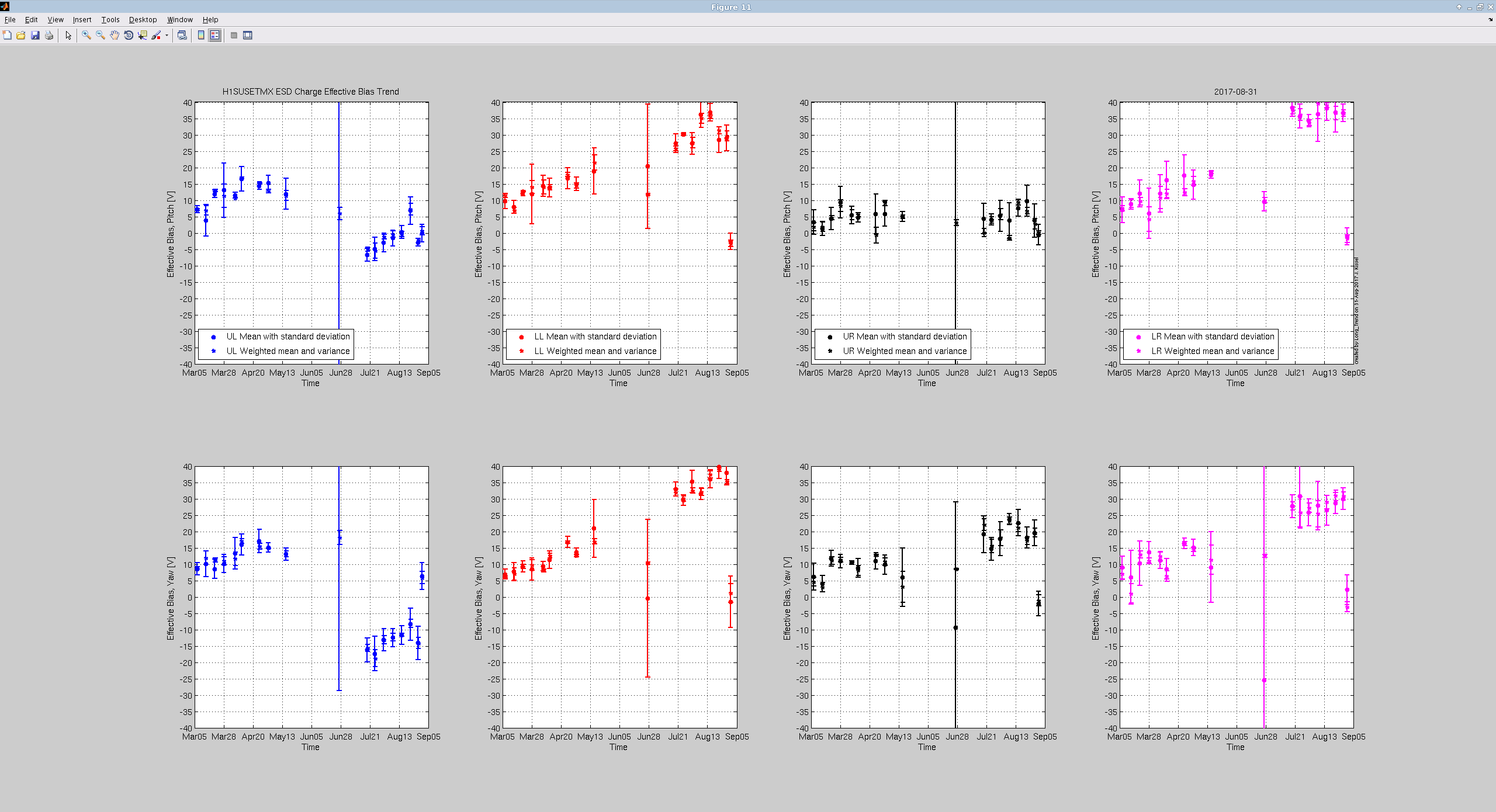
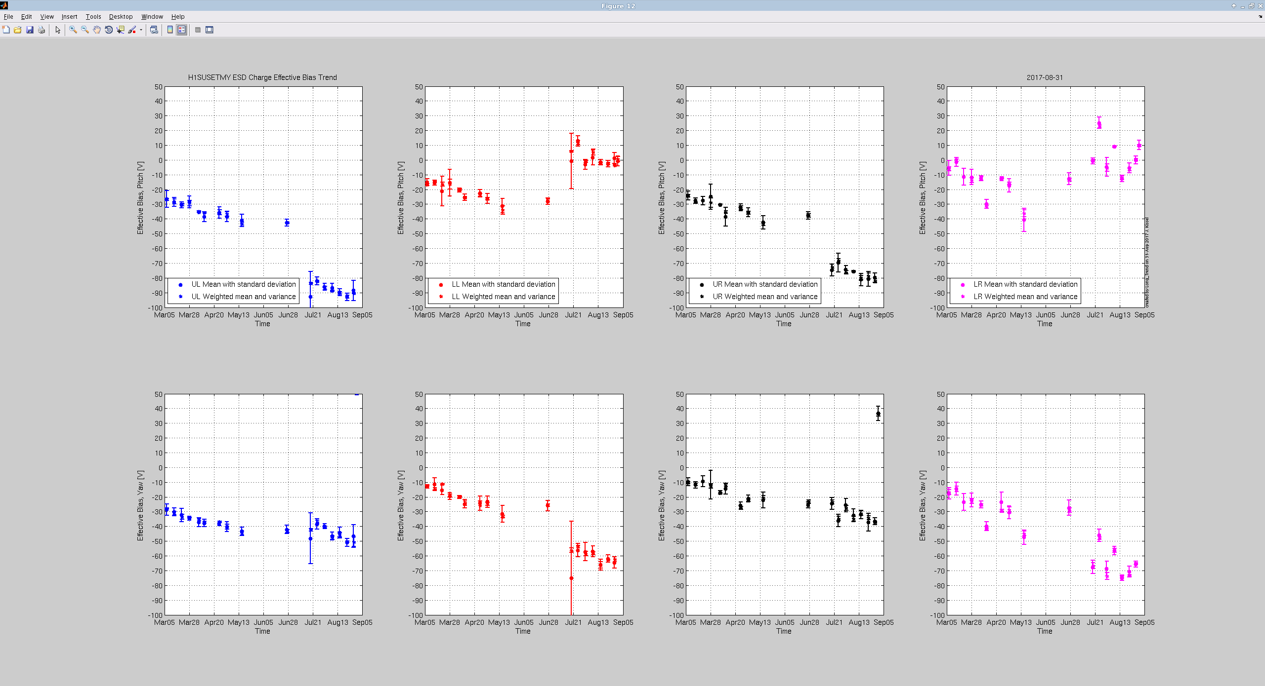
J. Kissel

I've measured the effective bias voltage of the H1SUSETMX and H1SUSETMY ESDs in the traditional fashion (as measured by the zero in actuation strength [rad/V_S] from each quadrant reported by the optical lever).
Excellent news: All Quadrants of ETMX ESD report 0 +/- 3 [V] effective bias voltage. AWESOME.
where, via the same, single-number metric (the mean and standard deviate of the weighted mean in all four quadrants, over two angular degrees of freedom), ETMX used to have 17 +/- 19 [V] effective bias voltage. Of course, you should look at the plots, since this single-number metric only works when all the weighted means of quadrants are very similar.

Note, however, this is a bulk measurement of all the ways that the ESD can be effected by charge. As Leo has discussed (see T1500467), and Sheila has recently resurrected (see LHO aLOG 38387), the force on the test mass is determined by

    F_ESD = A (V_B - V_S)^2 + B (V_B - V_S) + C (0.5*(V_B + V_S) - V_R)^2 + D (0.5*(V_B + V_S) - V_R) + E


where V_B, V_S, and V_R are the applied bias voltage, the applied quadrant control "signal" voltage, and the voltage of the surround cage components, respectively. A, B, C, D, and E are coefficients that depend on the geometry of the ESD pattern, the distance between the test mass & reaction mass, as well as the surrounding cage components (ring heater, EQ stops, fiber guards), and the polarizability of the test & reaction mass. This effective bias voltage measurement is a measure of a collection of all but one of these coefficients,
    V_eff = 0.25 (D - 2 C V_R - 2 B) /  (C - 4 A)

Once we recover the interferometer, Sheila and I will remeasure each coefficient independently, a. la LHO aLOG 38387, and BSC ISI excitations as in LHO aLOG 38132. Let's hope this has some impact on the sensitivity.

ETMY's effective bias voltage remains high (using the above metric, 51 +/- 34 [V]), but we're attacking the charge on that chamber next week. May we have the same amounts of success there!

Three cheers for Rai and the systems design team!
Excellent!
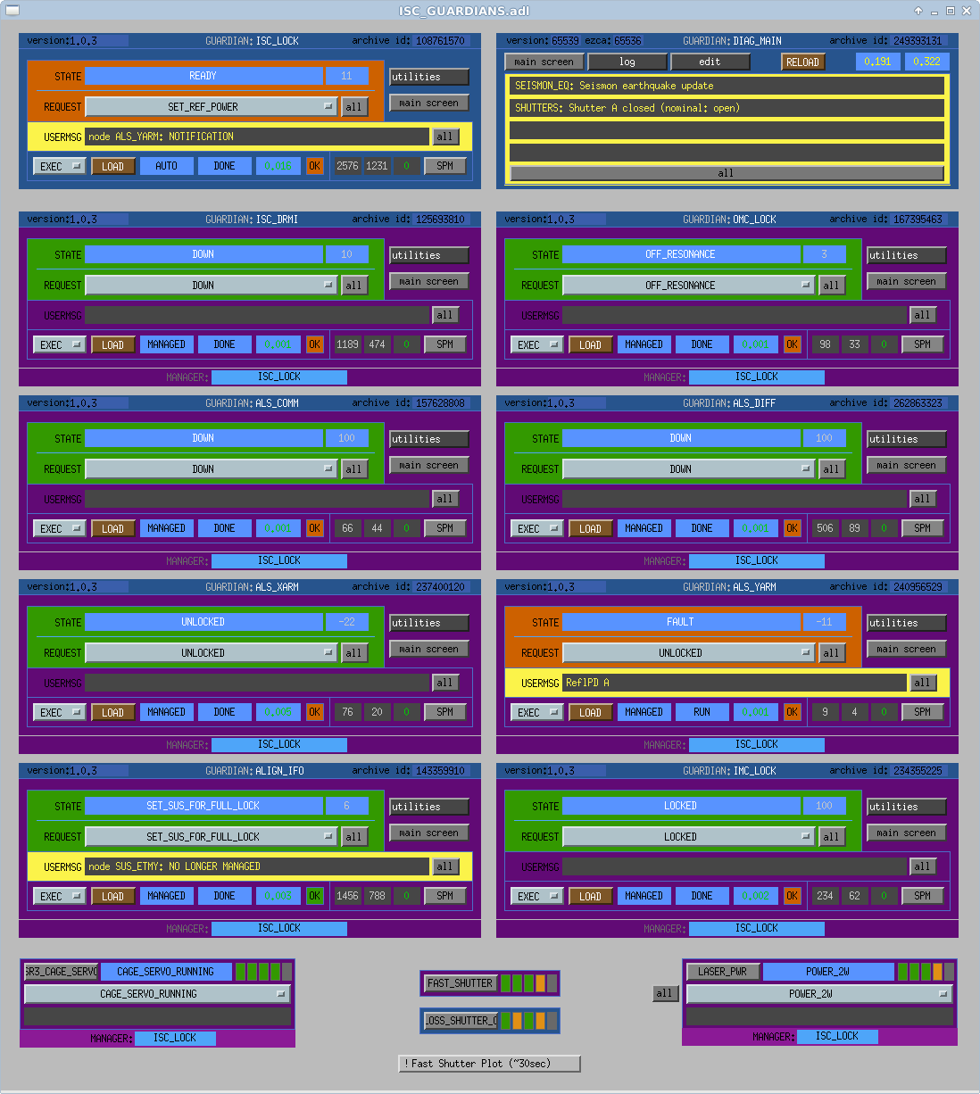
J. Kissel

For sanity's sake -- especially when trying to lock ALS COMM and DIFF by hand -- I've re-arranged the
     /opt/rtcds/userapps/release/isc/h1/medm/ISC_GUARDIANS.adl
ISC Guardian Overview screen to align the ALS_XARM node control underneath the ALS_COMM guardian node control, and similarly, the ALS_YARM underneath the ALS_DIFF node control. The arrangment had been confusingly the opposite since the screen's inception, I think.

The update has been committed to the repository.
TITLE: 08/31 Day Shift: 15:00-23:00 UTC (08:00-16:00 PST), all times posted in UTC
STATE of H1: Commissioning
OUTGOING OPERATOR: None
CURRENT ENVIRONMENT:
Wind: 6mph Gusts, 4mph 5min avg
Primary useism: 0.01 μm/s
Secondary useism: 0.16 μm/s
QUICK SUMMARY:
Kyle & Bubba are prepping for GV20 opening at EX (after work permit signed) this morning.
As of last night the game plan for the morning was also to have charge measurements run for ETMx and then start locking late morning/afternoon.
IFO Status:
Kyle, John

Two additional discharge cycles, in addition to yesterday's single cycle, were completed by D. Sigg, J. Kissel and N. Mavalvala today.  Following the final gas admission, and with the X-end pressure at ~16 Torr or so and the TMDS port isolated, John and I decoupled the Surface Disharge Ionizer from BSC9 and installed a 2.75" blank in its place.  I then opened the 1.5" TMDS port gate valve and "burped" these few ccs of room air into the X-end vacuum volume.  This valve was then left open.

I roughed down using the QDP80 to 0.5 Torr < pressure < 1.0 Torr before spinning up the Turbo.  This is the same approach as was used for the previous two pump downs.

I am leaving the X-end on the Turbo overnight and plan to execute WP #7134 in the morning.
Factor of 10 between gauges. PT510 is a 20 yr. old cold cathode and PT525 is 2 yr. old Bayard-Alpert parani wide-range. I'll think about this tomorrow ;)
It looks like PT525 is non-changing?
Daniel, Marc, Paul, Fil
Making good use of IFO down time today, we installed squeezer modifications to both Corner 4 and Corner 6 chassis. In theory, this completes the squeezer modifications to slow controls in the CER.
TwinCAT was down overnight due to a problem with the EK1100 on corner 6 right rail. We swapped the terminal and it is now working.
TITLE: 08/30 Day Shift: 15:00-23:00 UTC (08:00-16:00 PST), all times posted in UTC
STATE of H1: Commissioning
SHIFT SUMMARY:
Gate Valve for EX has been closed all day today for TMDS work. This allowed for active work on the floor throughout the site. The plan is to open EX gate valve in the morning, measure charge, and then try to locking H1 in the afternoon. In parallel staging for TMDS at EY may happen tomorrow.
LOG:
J. Kissel, N. Mavalvala, K. Ryan, D. Sigg

We've successfully completed the third and final cycle of the Test Mass Discharge System on H1 SUS ETMY (BSC9/BSC5).

All methodology and numbers ran very similar to the second session (LHO aLOG 38453), and the latter half of the first session (LHO aLOG 38430).
Because I was operating the knobs, my electrometer square wave voltage when measuring the ion "current" was 22.4 V (the maximum), instead of the previous runs in which Nergis measured with 12 V. After noticing the difference, we checked the electrometer's measured ion "current" at both 22.4 and 12 V, and measured similar values, so I stuck with 22.4 (cause it was easier just to crank the dial to max vs. find where 12 V was on the scope). See the attached notes for any further detail.

Also of note, we noticed about a factor of 2 (maybe 1.5) increase in electrometer-measured ion "current" (voltage) from +/-4.5 to +/-9 [Vp] when the TMDS system's scroll pump is ON vs. OFF (while the whole system is still valved off to the chamber). Maybe the scroll pump is sucking up ions from the electrometer? Still no explanation as to why we're getting a factor of 1.5 less "current" than LLO -- again, Ryan's report during their Jul 2016 TMDS run (LLO aLOG 35636, they were able to get upwards of +/- 12 to 13 [V]. Nergis suggests it's a function of calibration on the electrometer.
The input impedance into the D1500061 electrometer board is 1e9 ohms. While this is relatively low in terms of the issues with contamination associated with electrometers having 10 to 100 times this input impedance, it is still feasible that somewhere in the chain of components from the pickup electrode to the input pin of the electrometer IC, that there is some parallel resistance associated with either moisture, or contamination. This would cause an apparent decrease in the measured current. A simple calibration might be possible by ordering a glass encapsulated 1e9 ohm resistor, cleaning it well, and using it as part of a voltage divider. The voltage divider formed by this glass resistor and the input impedance to the electrometer might be used to check the calibration via the normal electrometer output.
Sheila plans to come in and lock the IFO this afternoon, so that I can try to finish these detchar safety injections. I've schedule 7 injections, the first one will begin at 16:06:22 PDT, and the last at 16:51:22 PDT. Here is the update to the schedule:
1187824000 H1 INJECT_DETCHAR_ACTIVE 0 1.0 detchar/detchar_27July2017_PCAL_{ifo}.txt
1187824450 H1 INJECT_DETCHAR_ACTIVE 0 1.0 detchar/detchar_27July2017_PCAL_{ifo}.txt
1187824900 H1 INJECT_DETCHAR_ACTIVE 0 1.0 detchar/detchar_27July2017_PCAL_{ifo}.txt
1187825350 H1 INJECT_DETCHAR_ACTIVE 0 1.0 detchar/detchar_27July2017_PCAL_{ifo}.txt
1187825800 H1 INJECT_DETCHAR_ACTIVE 0 1.0 detchar/detchar_27July2017_PCAL_{ifo}.txt
1187826250 H1 INJECT_DETCHAR_ACTIVE 0 1.0 detchar/detchar_27July2017_PCAL_{ifo}.txt
1187826700 H1 INJECT_DETCHAR_ACTIVE 0 1.0 detchar/detchar_27July2017_PCAL_{ifo}.txt
The IFO should be left out of observation mode. Also, I'm not sure if the PCALX 1500Hz line gets turned back on, but this also needs to be turned off. Simply typing the following on the command line will do the trick:
caput H1:CAL-PCALX_PCALOSC1_OSC_SINGAIN 0
caput H1:CAL-PCALX_PCALOSC1_OSC_COSGAIN 0
The interferometer is locked in Nominal low noise and the PCAL X 1500 kHz line is off as of 22:55 UTC. I hope that the BS ISI will not trip during the injections. (alog 38382)
The interferometer unlocked just before 1187825964, so I think that 4 or 5 of these injections would have completed before it unlocked. I don't know why it unlocked.
According to the guardian log (see attached), the first 5 of these injections made it in. The fifth one ended at 1187825913 (about 50secs before the lockloss). This should be enough injections for now. Thank you Sheila for coming in on a Saturday afternoon and locking the IFO for us!
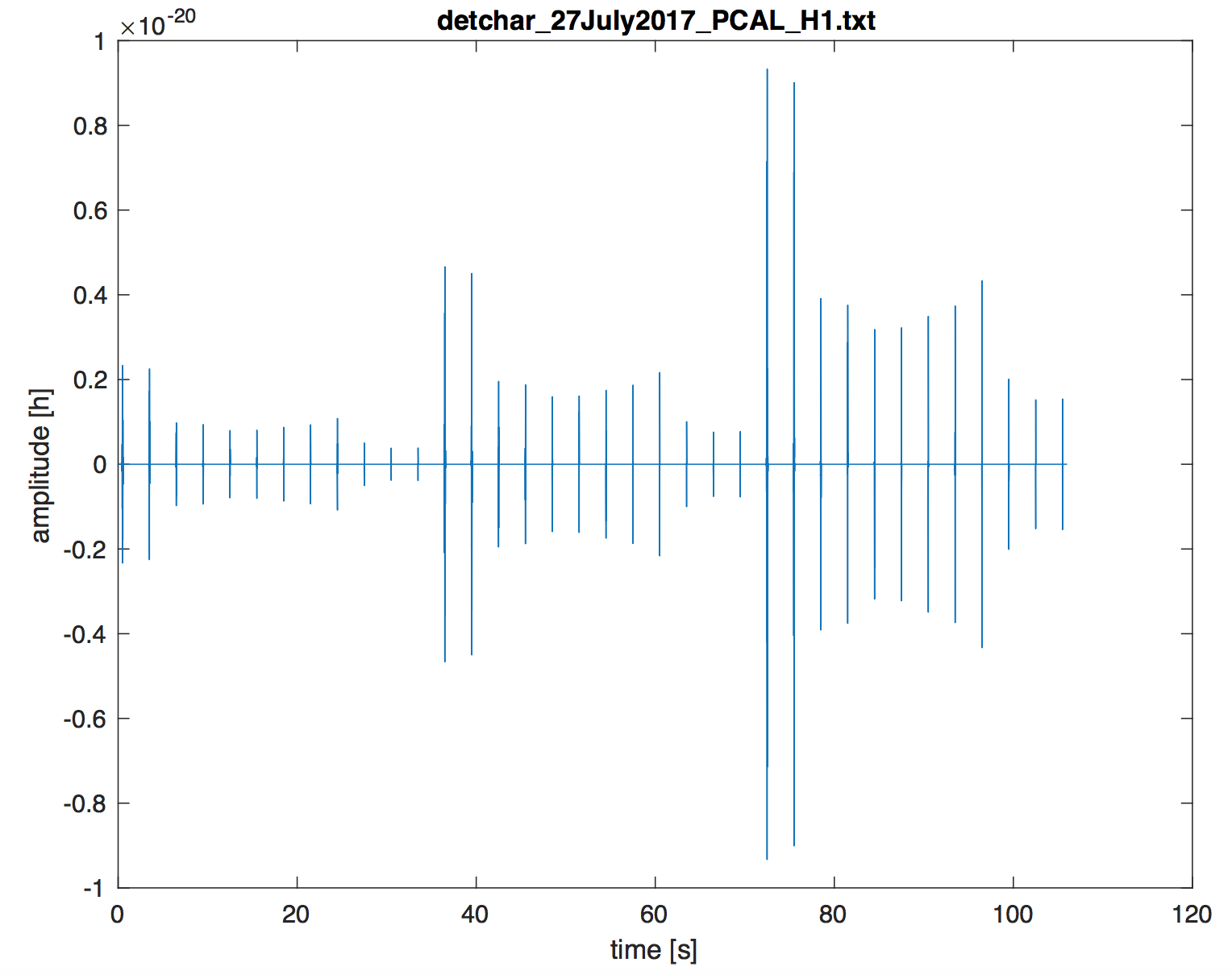
Short version: I made omega scans for the 5 sets of injections that were done above andyou can find them here: https://ldas-jobs.ligo-wa.caltech.edu/~jrsmith/omegaScans/O2_detchar_injections/ (note that after the first set the rest of sub-directories of the start time for each set).
Long version: The Injection files are here: https://daqsvn.ligo-la.caltech.edu/svn/injection/hwinj/Details/detchar/. These are timeseries sampled at 16384 Hz and they start at the injection times listed in the original entry above. Times of the injections start 0.5s after times given in alog, and are separated by 3s each. Some simple Matlab to plot (attached) the injection file and print a list of times is:
% Plot hardware injections
fnm = 'detchar_27July2017_PCAL_H1.txt';
data = load(fnm);
t = 0:1/16384:(length(data)-1)*1/16384;

figure;
plot(t,data)
xlabel('time [s]')
ylabel('amplitude [h]')
title(strrep(fnm,'_','\_'))
orient landscape
saveas(gcf,'injections.pdf')

% Print times of injections
t_start = 1187824000+0.5;
times = t_start:3.0:t_start+106;
fprintf('%.2f
',times)
To submit the omega scans I used wdq-batch like so: (gwpysoft-2.7) [jrsmith@ldas-pcdev1 O2_detchar_injections]$ wdq-batch -i H1 times-1.txt, then submitted the resulting dag to Condor.
OmegaScan results are here: https://ldas-jobs.ligo-wa.caltech.edu/~jrsmith/omegaScans/O2_detchar_injections/
These will take some hours to run and we will then look at the results to see if there are any obvious unsafe channels. In addition we'll look statistically using hveto.
This is the equivalent comment to the comment for L1's detchar injections hveto safety analysis on page 35675
I ran hveto_safety on the injections mentioned above, looking for coincidences within 0.1sec time window.
The results of the analysis using >6 SNR omicron triggers can be found here: https://ldas-jobs.ligo-wa.caltech.edu/~tabbott/HvetoSafety/H1/O2/safetyinjections/D20170826/results/H1-HVETO_omicron_omicron-1187823990-125/safety_6.html
The configuration for the analysis can be found here: https://ldas-jobs.ligo-wa.caltech.edu/~tabbott/HvetoSafety/H1/O2/safetyinjections/D20170826/results/H1-HVETO_omicron_omicron-1187823990-125/H1-HVETO_CONF-1187823990-125.txt
I missed that there we 4 extra sets of injections, so I've redone the hveto safety analysis on the complete set of 180 injections.

