jeffrey.bartlett@LIGO.ORG - posted 10:21, Wednesday 09 August 2017 (38100)
LVEA Sweep
TJ swept LVEA before the start of commissioning. He unplugged one unused extension cord.
TJ swept LVEA before the start of commissioning. He unplugged one unused extension cord.
TITLE: 08/09 Owl Shift: 07:00-15:00 UTC (00:00-08:00 PST), all times posted in UTC
STATE of H1: Observing at 53Mpc
INCOMING OPERATOR: Jeff
SHIFT SUMMARY: No issues to report.
LOG:

14:36 UTC Ken pulling wire in OSB.
Have remained in observing. No issues to report.
TITLE: 08/09 Owl Shift: 07:00-15:00 UTC (00:00-08:00 PST), all times posted in UTC
STATE of H1: Observing at 54Mpc
OUTGOING OPERATOR: Ed
CURRENT ENVIRONMENT:
Wind: 5mph Gusts, 2mph 5min avg
Primary useism: 0.04 μm/s
Secondary useism: 0.06 μm/s
QUICK SUMMARY:
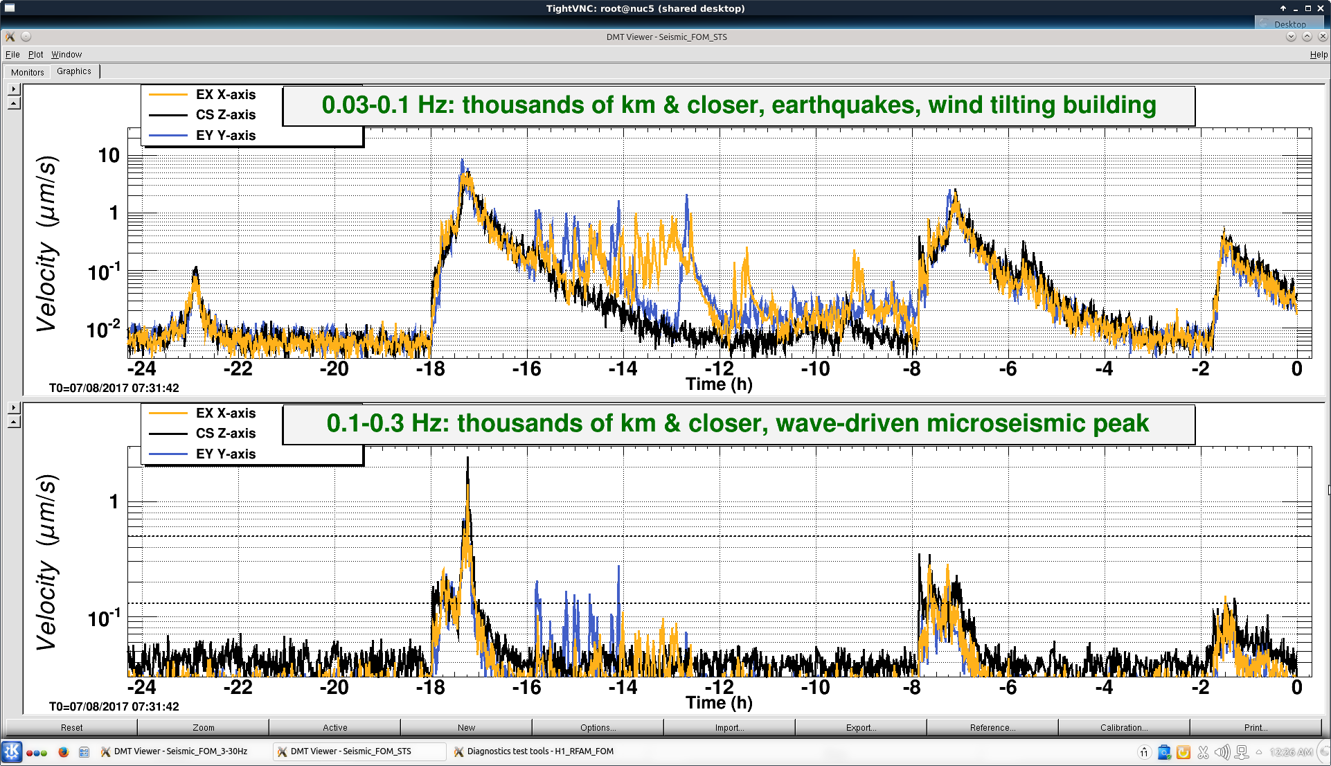
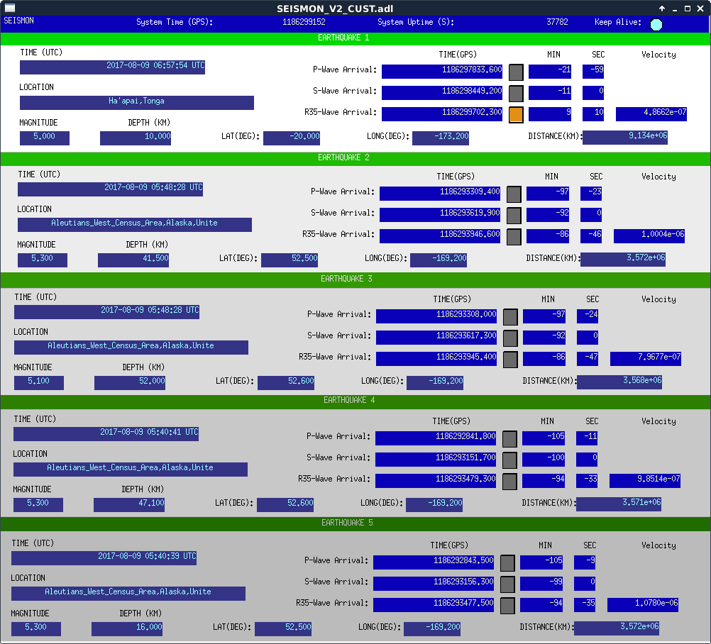
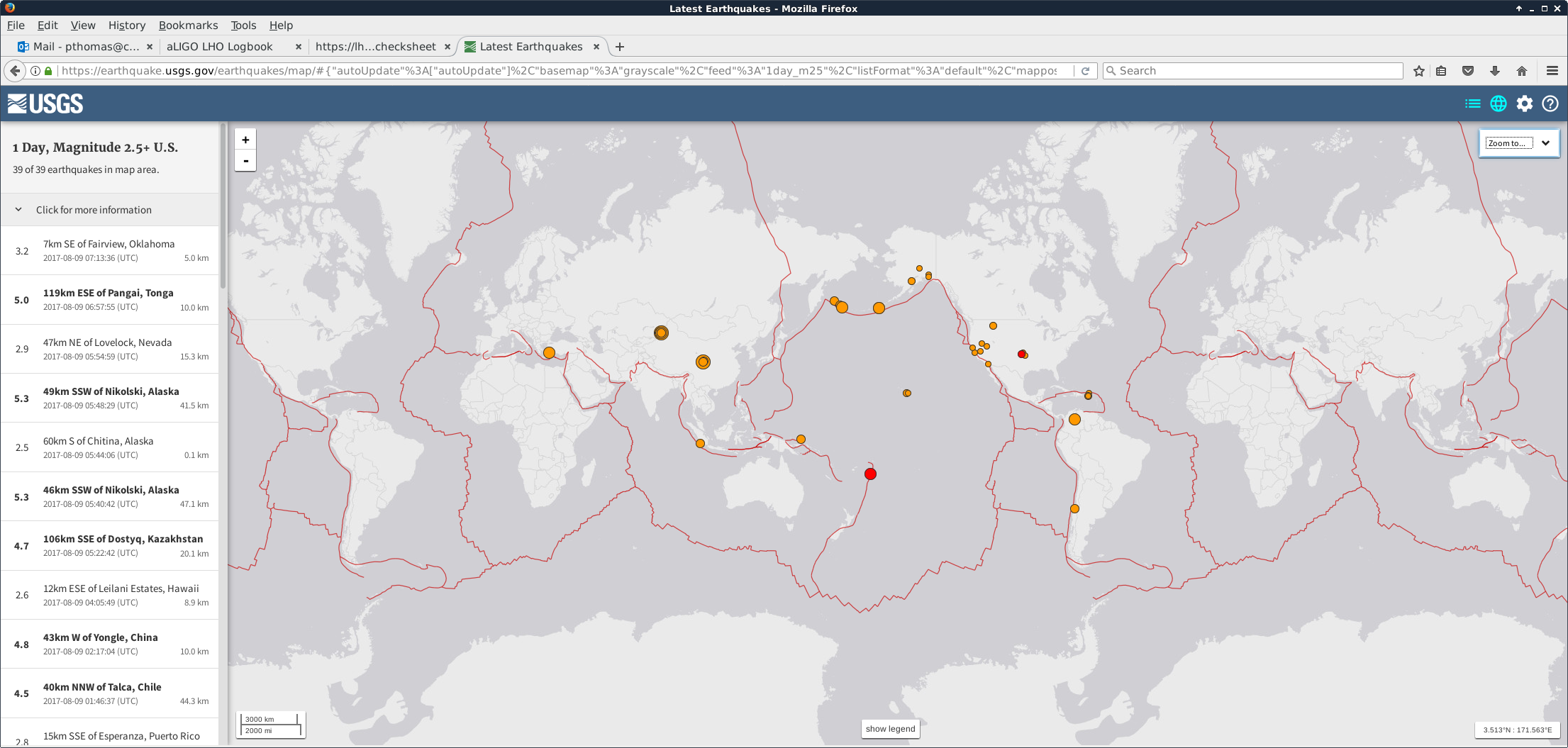
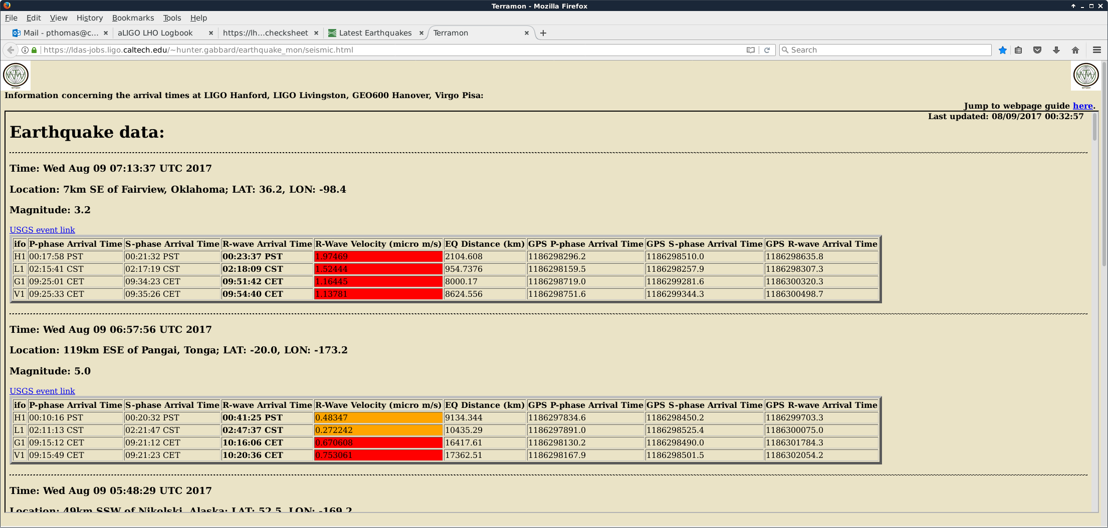
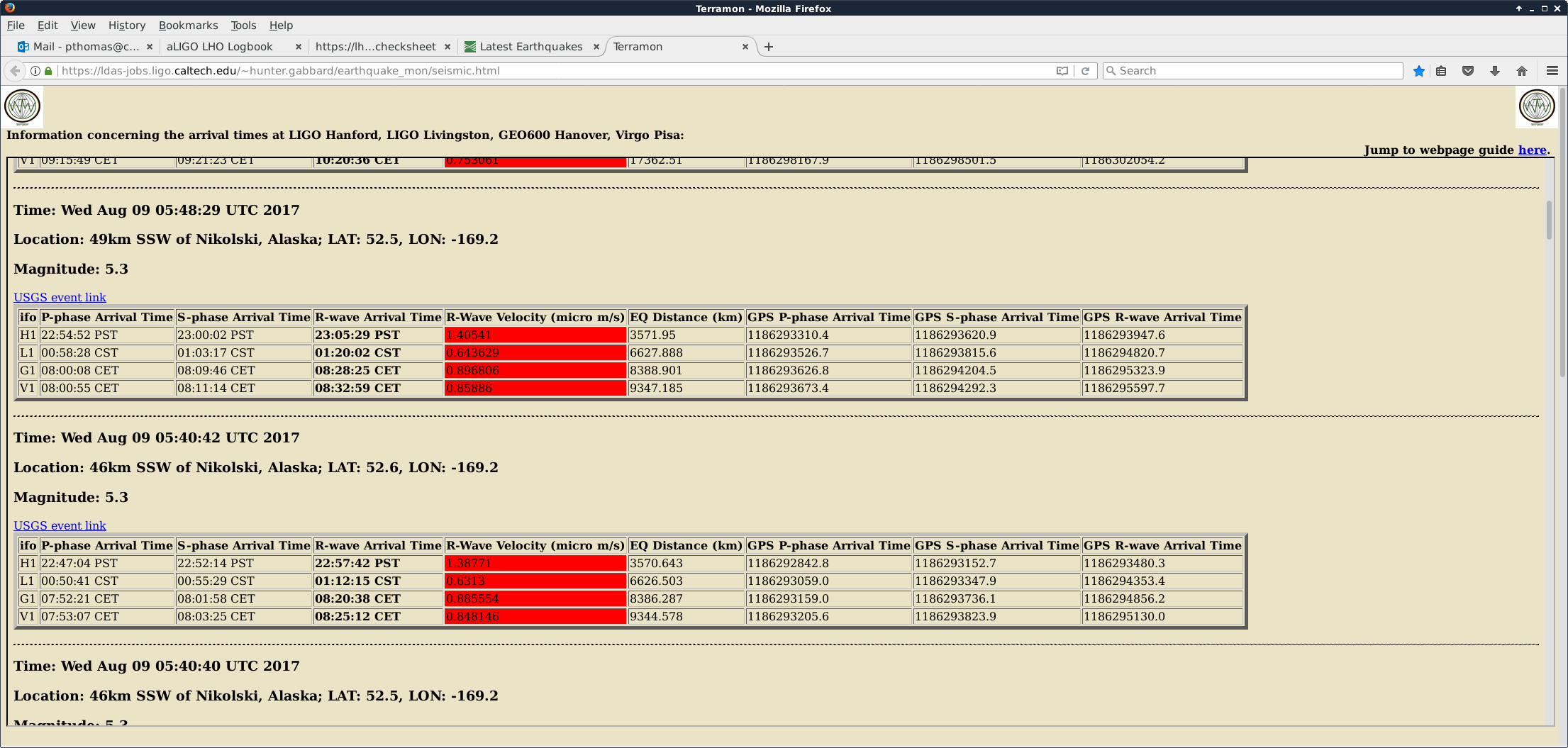
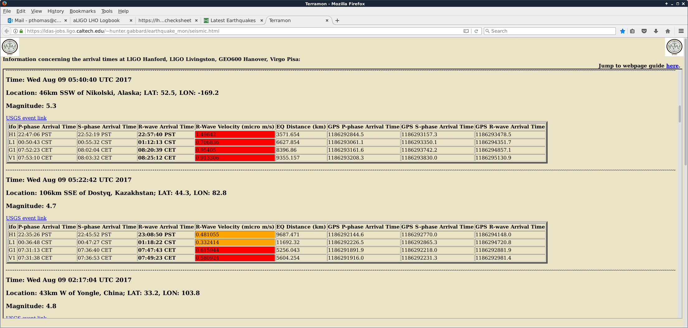
0.03 - 0.1 Hz seismic BLRMS is coming down from after earthquakes near Alaska.
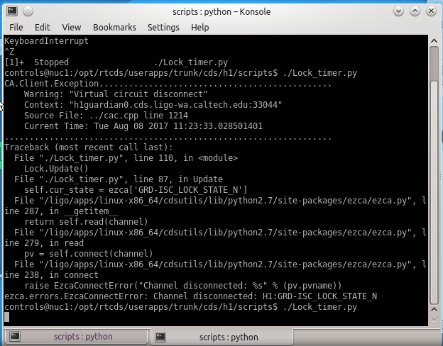
07:25 UTC Lock clock not updating. Lock timer python script not running. Started. Screenshot attached.
TITLE: 08/09 Eve Shift: 23:00-07:00 UTC (16:00-00:00 PST), all times posted in UTC
STATE of H1: Observing at 53Mpc
INCOMING OPERATOR: Patrick
LOG: N/A
SHIFT SUMMARY:
Mid_Shift Summary (never got posted)
After many failed attempts to recover lock after the EQ(s), I performed initial alignment. The furthest I've been able to get thus far is LOWNOISE_ESD_ETMY. I had to pause at DC readout to tame some ETMX violin modes.
Lockloss problems included:
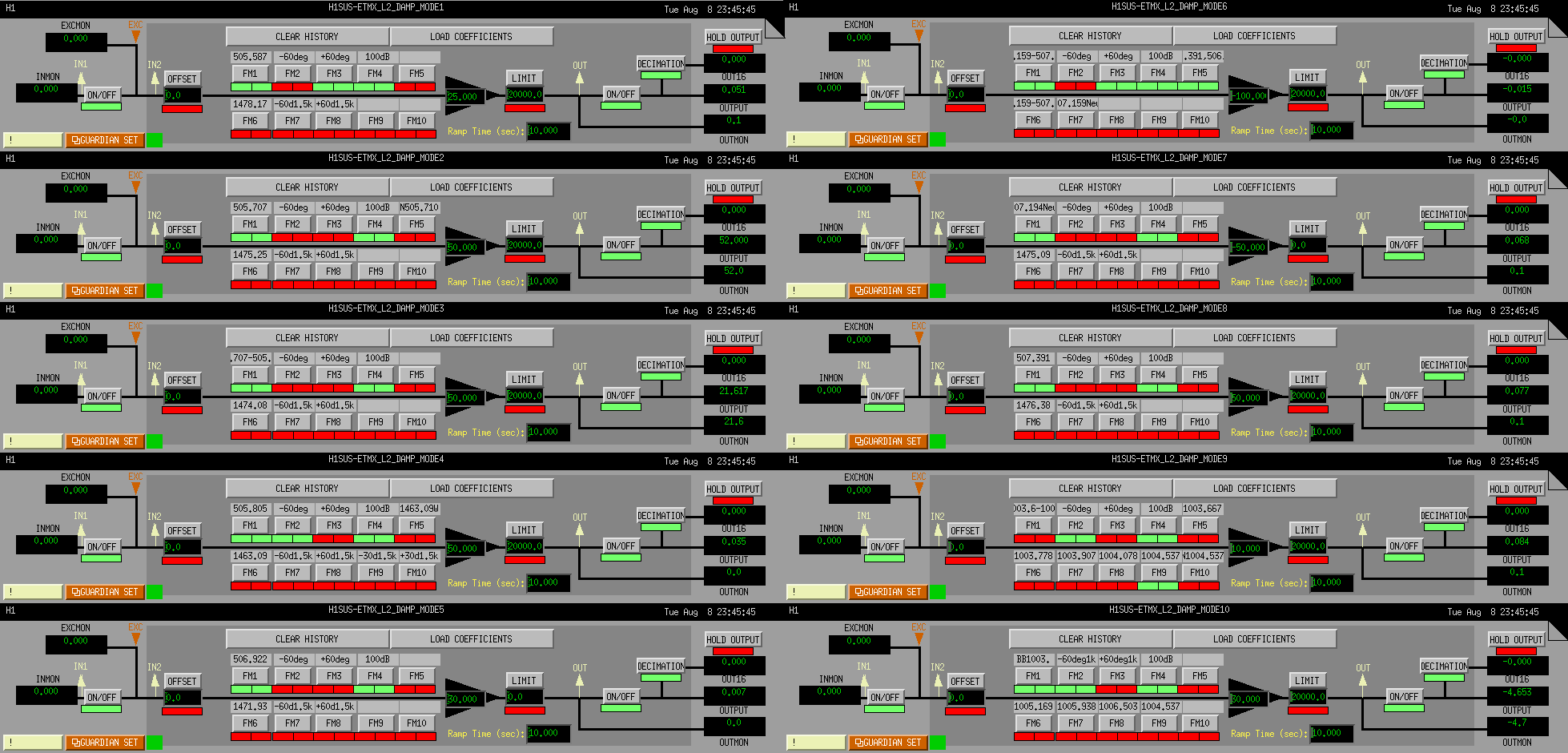
ETMX Violin Mode damping:
Lots of phone time with Sheila got H1 back in business.
I'd like to suggest that next time an earthquake takes us down we wait to re-lock and assess any artifacts from the event before beginning maintenance on the IFO and then take it down on our own terms to begin making changes.
06:27 H1 back to Observing
23:50UTC whilst trying o acquire lock and 95% of the way there, a 6+mag EQ in Khazakstan‌ took us down. The Observatory mode wasn't switched to environment until 00:40. Apologies for the late action.
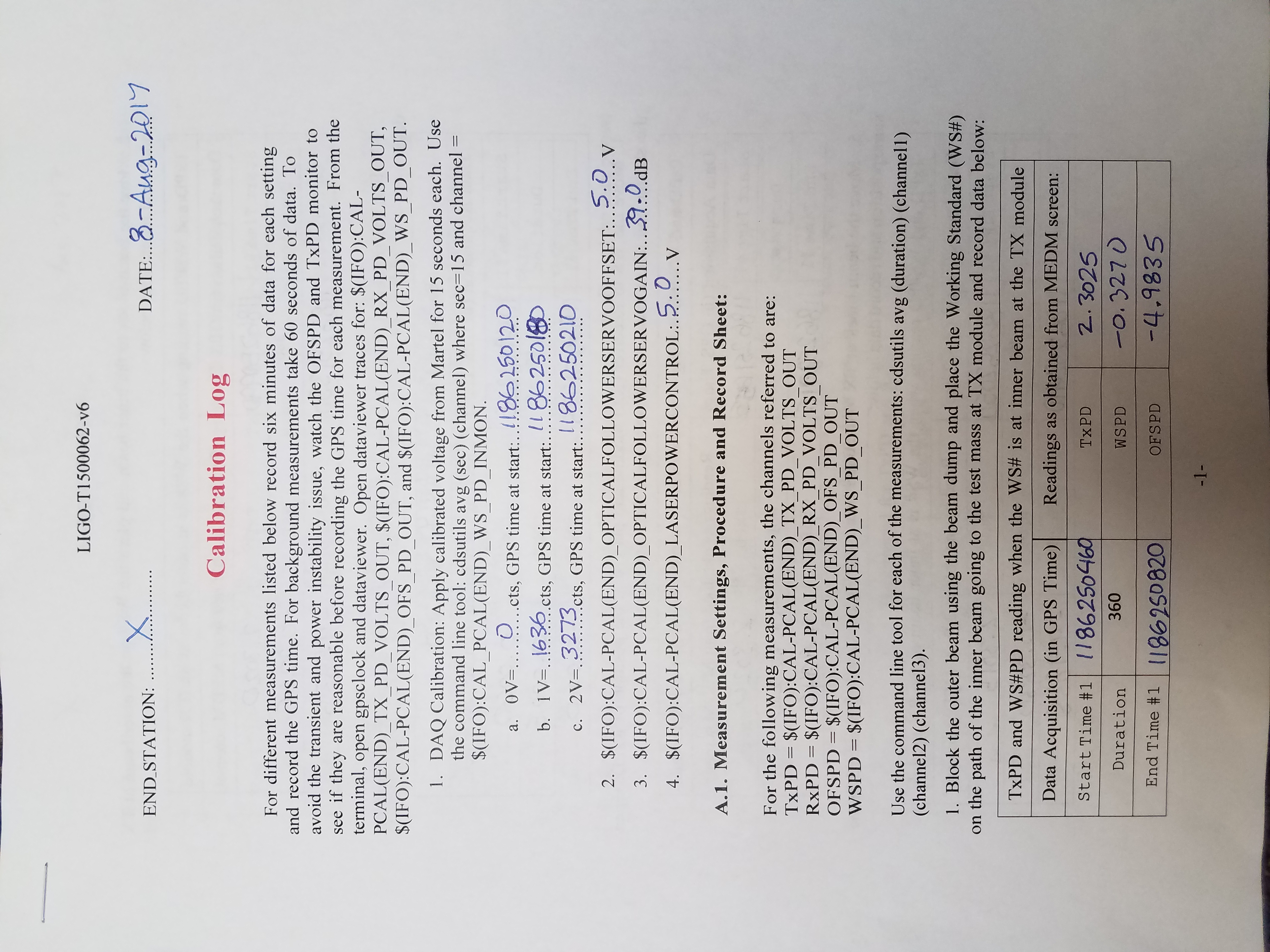
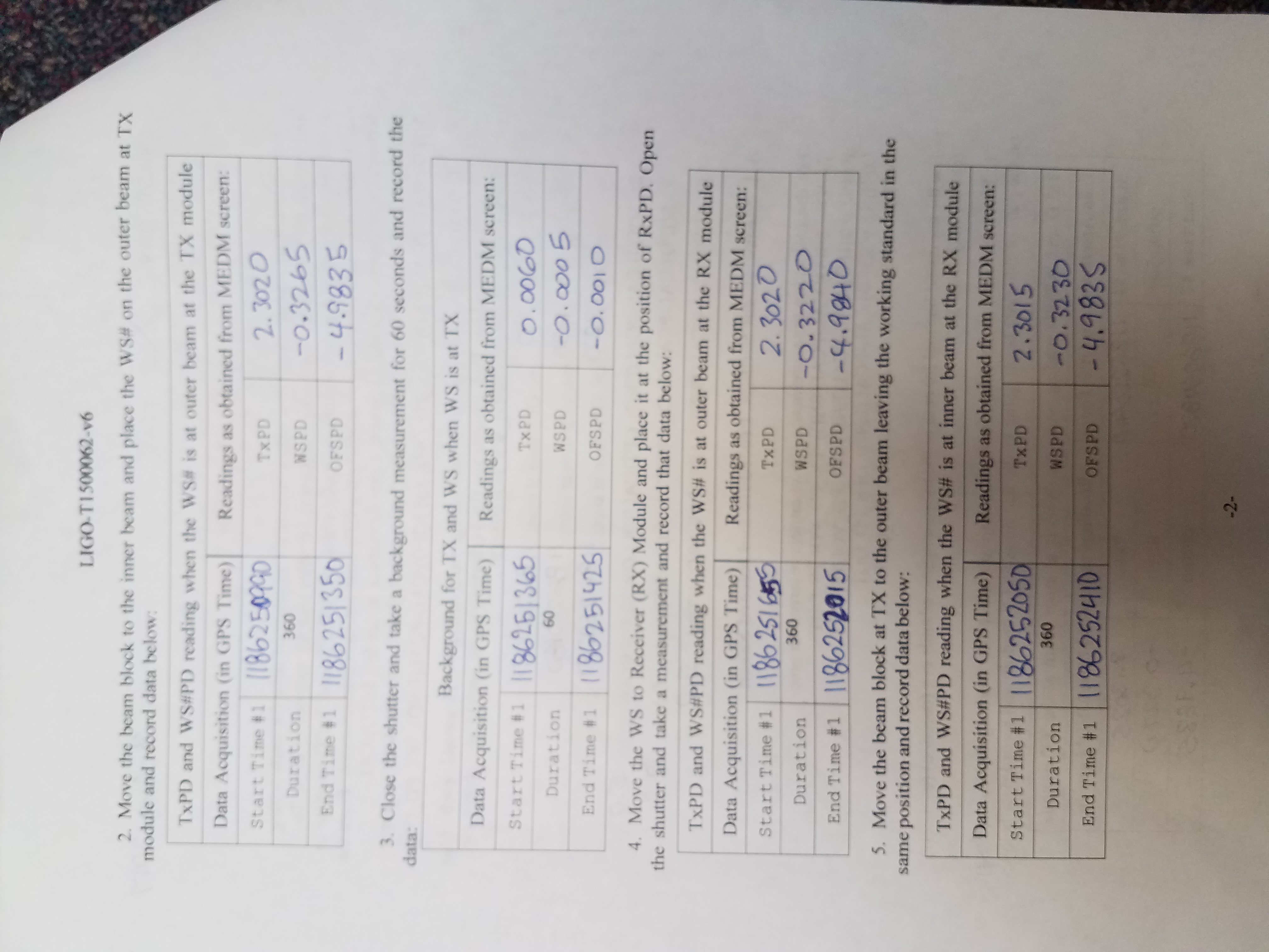
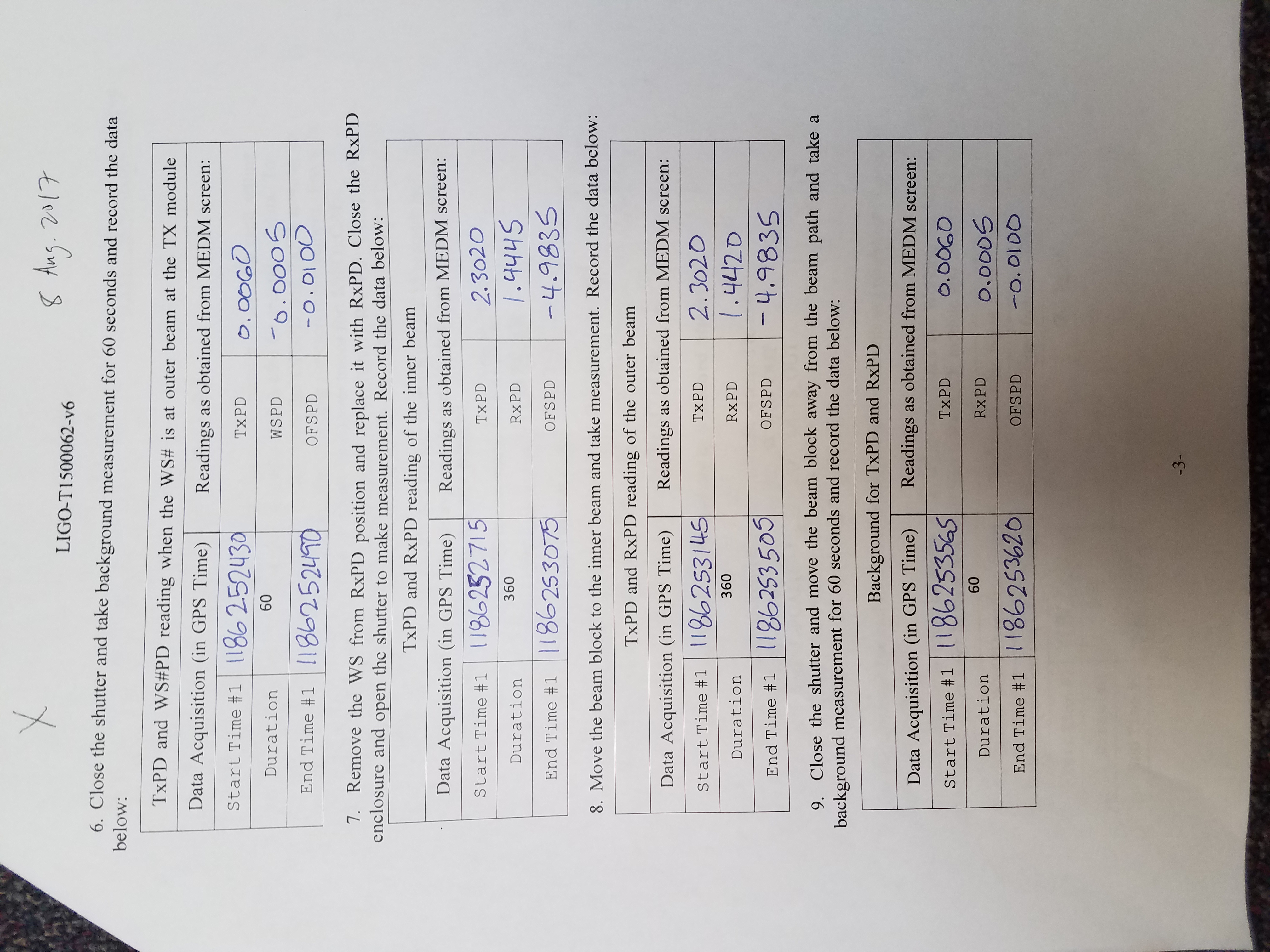
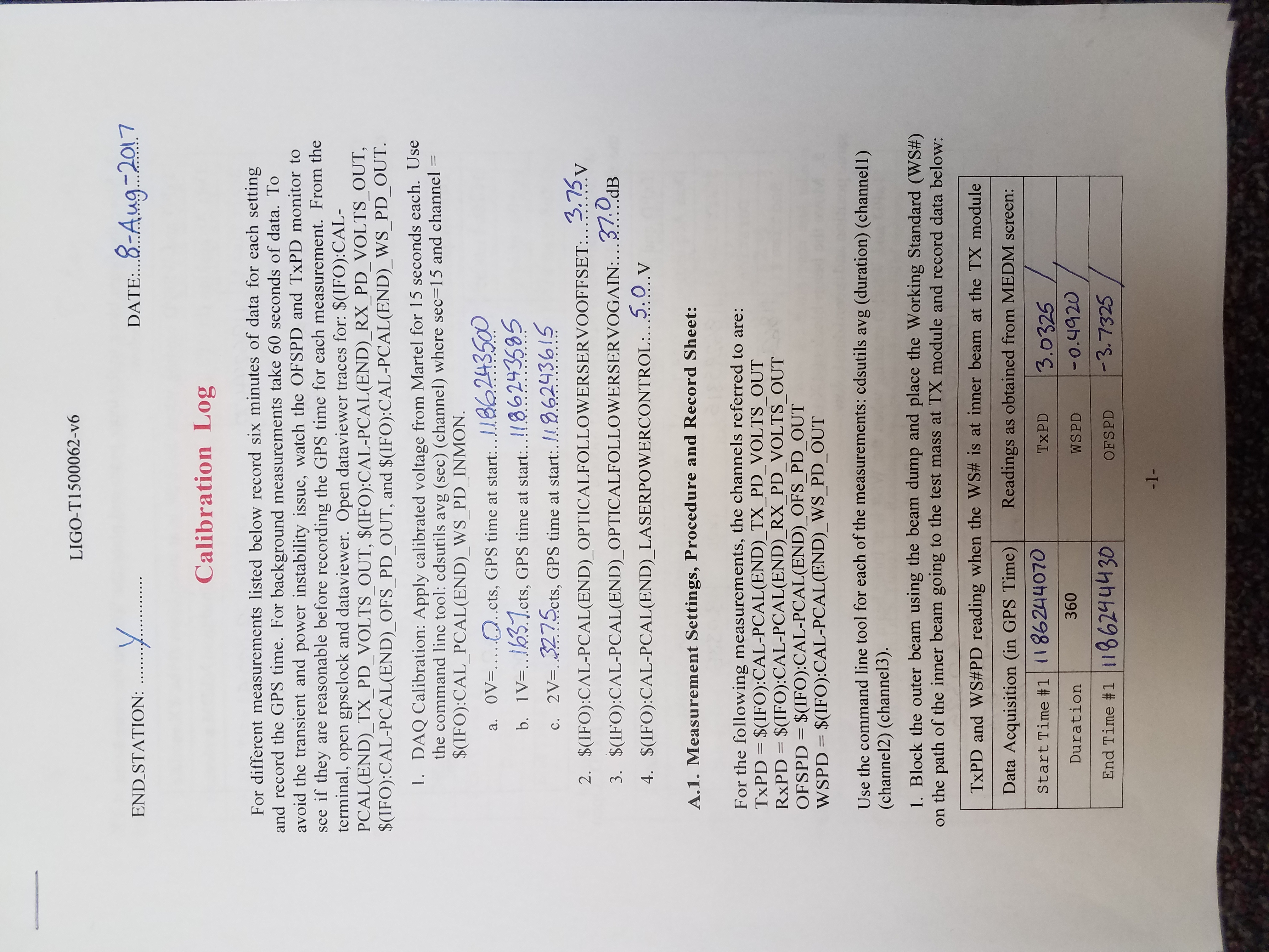
Both X and Y End Stations had their pre-end-of-O2 calibration measurements today. Full results can be found for: EndX and EndY. The resulting PCal Force Coefficients are:
Currently used O2 force coefficients:
LHOX: none, not used
LHOY: RxPD = 1.0475e-9 N/V
TxPD = 1.5160e-9 N/V
This measurement:
LHOX: RxPD = 1.0473e-9 N/V
TxPD = 1.3164e-9 N/V
LHOY: RxPD = Not calculated due to clipping
TxPD = 1.5202e-9 N/V
Note: The values I list for "This measurement" don't match what is shown in the results found at the links posted above. This is due to the fact that we calculated these numbers by hand since they are corrected for optical efficiency, which we know to be an issue related to the known clipping. We used the optical efficiency that was measured in previous measurements before clipping started.
For LHOY TxPD, this give us 0.28% variation between this measurement and the O2 epics value.
Log sheets for this round of calibrations attached.
TITLE: 08/08 Eve Shift: 23:00-07:00 UTC (16:00-00:00 PST), all times posted in UTC
STATE of H1: Preventive Maintenance
OUTGOING OPERATOR: Travis
CURRENT ENVIRONMENT:
Wind: 11mph Gusts, 7mph 5min avg
Primary useism: 0.02 μm/s
Secondary useism: 0.06 μm/s
QUICK SUMMARY:
Currently trying to debug ALS troubles. Sheila is on the case.
The ALS troubles described above went away on their own. I dont know what happened.
Today I connected the TMDS Gas Delivery Table to the 100 psi tap of the X-end vent/purge air supply and let the dry air flow through the table's plumbing.  The ionizer assembly, scroll pump, 6' of 1" SS tube and 3' of 3/8" copper tubing which would nominally be connected during an actual discharge exercise were not connected.  As such, the air exhausted into the room instead.  I had to make a few minor "tweeks" and fix a few leaks.  The observed flow rate (rotameter) was ~50-60 lpm for ~20-25 psi regulator output.  This is consistent with the flow vs. pressure relationship observed by LLO (see Harry, Ryan, Scott notes "TMDS_ETMX_2-3-16.pdf" from LLO log entry?)

I shut down the vent/purge compressors and removed the TMDS table from the VEA (brought it back to the Corner Station Mechanical Room).  I will now remove the table's various plumbing components and have them cleaned.

NOTES TO SELF:  Compressor #4 needs a replacement pressure relief valve.  The 1" MNPT to 1" tube adapter at the VEA point-of-use valve is still leaking.  Need to adapt one of the various iLIGO aluminum billet "door stops" to serve as a pipe support for the 1" line that will route beneath the ISC table. The dedicated TMDS scroll pump has a factory label stating that it is configured for "US 120VAC" but, in fact, it is still configured internally for 220VAC - need to correct this before using.  Also, need to integrate the AC drop-out mechanism and NEMA 20 twist lock connectors to the scroll pump power cord.  Need to modify terminal cover and add 120VAC wiring for spring-close isolation solenoid valve.
Jonathan, Carlos, Dave:
the GraceDB database access certificate on h1fescript0 expired today, meaning that GRB and SN alerts could not be raised in the control room. Jonathan and Carlos obtained a new cert and installed it in record time. I noticed this machine had been running for 383 days, and needed a reboot to install patches, so I took this opportunity to reboot it.
There was some confusion on starting the seismon IOC code (currently we need both the old and new code), and I missed the restart of the camera copy program.
I'm updating the relevant CDS wiki pages related to code running on this machine.
Installed cable roller guides (pulley) in cable tray from CER to HAM6.. This is in preparation for pulling in the new RF and DC cabling for SQZ.
On the Pump Station output line below the reservoir is found a pressure relief valve. This valve is factory set to 125psi but this looks very coarse. The output from the valve is plumbed to a small drum. I found this clear line full of fluid. This suggests to me there have either been several pressure spikes on pump station restart--not good; or, a slowly leaking valve--less bad but still not ideal. I've drained the line as best I can and marked the hose for monitoring.
The pressure spikes upon restart are caused by poor operation (not following the restart guidance: https://cdswiki.ligo-wa.caltech.edu/wiki/SEI) and should be avoided to limit fluid loss and disposal pain down the road. Plus, the system will very likely have not successfully restarted if the best practice has not been followed.
The attached plot shows the pump drive and the output pressure closest to the relief valve during the July 29 OU3 fault. The bottom plot is zoomed into the pressure during restart attempts. The bottom line to remember when operating this system is to manually zero the PID output before pressing the red button or hitting the fault reset. The PID loop knows nothing about the VFD (maybe this will change with potential Beckoff upgrade.) It knows only that the process variable differential pressure is not at the process setpoint. So the PID increases the output to max. In this state, as shown in this trends, the reset button was pushed with the VOUT at max and as a result the pressure spikes to more than 100psi very quickly. Whether this spike opens the relief valve is unknown--these EPICS trends could easily not show the highest pressure, the relief valve and this pressure gauge are likely not tightly calibrated. Couple things could happen with this spike occurs: the relief valve opens and spills fluid; and/or, the fluid level in the reservoir is pulled down too quickly and the pump station trips. Obviously something like this happened twice here. Once the VOUT was zero'd, restart proceeded nicely.
Again, bottom line, Operators--If the HEPI Fluid Pressure is not okay, manually reduce the output of the PID before pushing any hardware buttons.
Maintenance tasks: all times UTC
Current:
19:46 Fil to CER to pick up his notebook.
19:51 Fil out
19:50 Beginning Initial alignment.
19:55 Shiela and Thomas to End stations to revert ETMX ESD Cabling
20:04 Jason to Mid X
20:30 Jason back
20:45 Having trouble keeping green arms locked, once ALS WFS + CAM are engaged, even with good flashes to start
      Found Green ITM camera image processing had stalled since h1script0 was rebooted.
21:00 Fire Alarm
21:15 Guardian node errors as a result of failed reverting of attempt to lock ALS on ETMY in the morning

Sheila and Thomas also went to EX to confirm that ESD EX is cabled up correctly.
While snooping, they found that C and D fault lights were on for the TMSX OSEM sat amps. Thinking this was a problem, we restarted the coil drivers twice (no change), then unplugged then reseated the CD to SatAmp cables at the satamp (no change). Then we remembered that the TMS's second top mass signal chain only runs 2 OSEMs on channels A and B, so C and D will always have fault lights on.
All cables and power restored, TMSX returned to normal functionality.
SudarshanK, RichardS
We moved the Pcal beam back to their optimal position at 111.6 mm away from the center of the optic. The actual position of the current Pcal beams (last column) along with the history of where they were are in the table below. The number quoted on the table are distance of Pcal beam (in mm) from their optimal position of [0, +/- 111.6] mm.
| Before 07/25/2017 | 07/25/2017 | 08/01/2017 | 08/08/2017 | |
| Upper Beam | [1.9, 0.3] | [2.5, -8.4] | [1.1, 14.5] | [0.8, 0.6] |
| Lower Beam | [-1.0, 0.3] | [-1.3, 8.6] | [-0.5, -14.1] | [-0.8, -0.2] |
We also re-centered the Pcal beams on the receiver side to relieve it from any clipping that was happening outside the vacuum. The spectra attached below shows no significant clipping on the Rx beams.
We will run a set of calibration lines (from 4501.3 - 1501.3 at 500 Hz interval) with this Pcal beam configuration for about a week.
After this Pcal beam configuration change, we turned on the two Pcal lines at 333.9 and 1083.3 Hz using Pcal at ENDX. We will collect about 2-3 hours worth of data after we acquire the lock and turned them off. We plan to initiate the HIGH_FREQ_LINES guardian node to acquire data at high frequency after that.
Cheryl asked for a command line program to write operations logs to a text file. I have created a simple bash script called oplog
Here is the help page (printed if oplog is called with no arguments, or a single 'help' argument)
david.barker@zotws6: oplog help
Usage:
oplog text to be entered into log file | Simple text entry
oplog 'text with non alpha-numberic characters' | Complex text entry
oplog help | Show this help page
oplog show | Print content of your log file
Each user has their own log file, dated with the current day's date, in the /tmp/directory. The log file can be listed with the 'oplog show' command
oplog show
Aug 08 2017 18:03:12 UTC one two three four
Aug 08 2017 18:03:32 UTC five six seven eight
Aug 08 2017 18:13:26 UTC here is a long text line, it has many characters - including a dash
Aug 08 2017 18:17:31 UTC how about
Aug 08 2017 18:17:40 UTC how about & character?
Aug 08 2017 18:18:02 UTC show
Aug 08 2017 18:29:29 UTC
Aug 08 2017 18:32:28 UTC show the text
Aug 08 2017 18:33:18 UTC reboot h1fescript0
following Ryan's excellent suggestion, the log file has been moved from the /tmp directory into the user's home directory as a 'dot' file, specifically from:
/tmp/<date>_<username>
to:
/ligo/home/username/.<date>_<username>
T Vo, Sheila
We measured a transfer function from PCAL X to DARM this afternoon. The attached screenshot shows a comparison of driving the ETMX ESD in the low noise state (with the settings that allowed us to transition to it from ETMY) and a drive to PCALX_DARM with the filters that Thomas copied from the ESD filter banks. The red trace (ref 14+15) were taken with a gain of -150 in the PCAL filter bank.
Based on this measurement, Thomas and I estimated this morning that we would need a gain of about -3000 in the PCAL X DARM bank to transition to PCAL X from the ESD, but that this would result in about 50 V rms on the OFS PD. (There is about -82 dB of gain between the OFS PD (in Volts) and the output of the PCALX DARM bank. This means that we would not have enough range on PCAL to simply replace the ESD with PCAL, so we have not tried the transition or locking ALS on ETMY.
If we aren't able to disconnect the ESD cables while in lock, we could look at using one of the ITM ESDs to transition from high voltage to low voltage on one ESD with the other disconnected. We also talked with Daniel, RIchard and Fil who had some ideas about different ways to try disconnecting the cables while in lock. We were about to try these when the EQ hit us.

