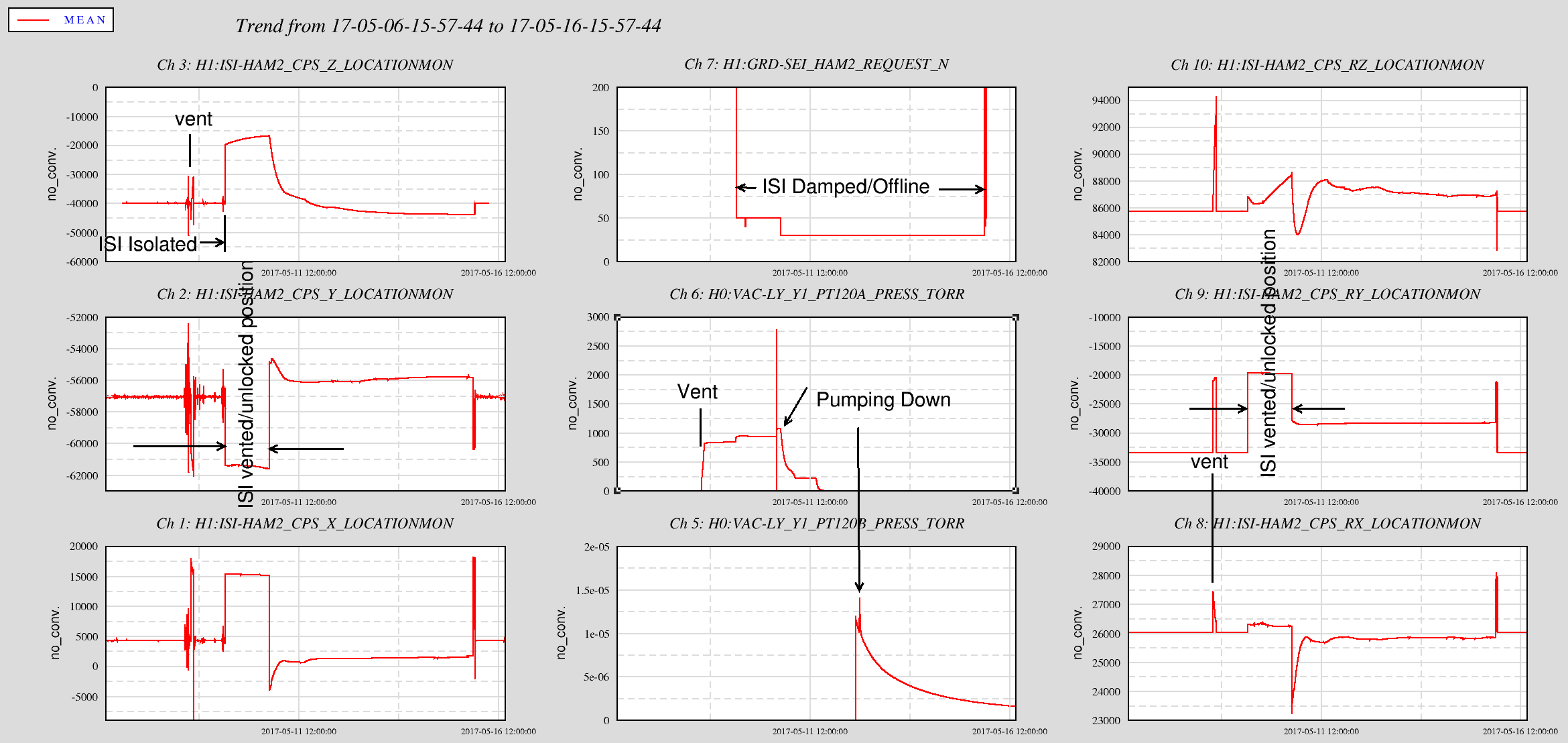
Displaying reports 50761-50780 of 86023.Go to page Start 2535 2536 2537 2538 2539 2540 2541 2542 2543 End
Reports until 14:38, Friday 19 May 2017
LHO General
vernon.sandberg@LIGO.ORG - posted 14:38, Friday 19 May 2017 (36290)
Work Permit Summary for 2017 May 16 Maintenance Day
Work Permit Date Description alog/status
6641 5/19/2017 11:34 Sunday evening, May 21st, give personal tour to one or two friends * Walk on Mezzanine in LVEA  
6640 5/18/2017 10:33 Opening GV 1,2 isolating vertex from x & y beam manifolds. The manifold turbos are ON and open to beam tubes. IP 5,6 are valved out. Pumped out gate annuli on both valves. This will allow access to oplevs/pcal camera to help with ITMx alignment and/or imaging. It could also speed up pump down time.  
6639 5/17/2017 10:33 Update and restart the Beckhoff PLC code on h0vacmr to match the IP6 controller change from a dualvac to a gamma. Due to the difference in the signals for the controllers, some EPICS channels will be lost and others added. Minute trend files may be renamed. Requires a DAC restart. Will update autoBurt.req file and MEDM screens. Will coordinate with the vacuum group. 36259, 36266
6638 5/17/2017 9:45 Trouble shoot a script that may have crashed the nds1 server. Run an instrumented copy of the operator alog summary script w/ a new nds2 client to see what caused problems. This should be done when users are not in the middle of large measurements in case we impact h1nds1 again.  
       
Past WPs      
6622 5/8/2017 7:15 Install Air Trap/Bleed (ECR #E1700096) in PSL Crystal Chiller return line. Will need the PSL to be down during the installation. 36223
H1 PSL
edmond.merilh@LIGO.ORG - posted 13:47, Friday 19 May 2017 (36289)
Water Added to Chillers

I forgot to log this action yesterday:

I noticed that the Diode Chiller alarm 'light' was flashing red, intermittently. I went into the chiller room and also noticed that the Xtal chiller was also a little low.

Long story short: I added 200ml to both.

LHO VE
logbook/robot/script0.cds.ligo-wa.caltech.edu@LIGO.ORG - posted 12:10, Friday 19 May 2017 - last comment - 14:47, Friday 19 May 2017(36288)
CP3, CP4 Autofill 2017_05_19
Starting CP3 fill. LLCV enabled. LLCV set to manual control. LLCV set to 50% open. Fill completed in 274 seconds. TC B did not register fill. LLCV set back to 21.0% open.
Starting CP4 fill. LLCV enabled. LLCV set to manual control. LLCV set to 70% open. Fill not completed after 3600 seconds. LLCV set back to 33.0% open.
Images attached to this report
Comments related to this report
chandra.romel@LIGO.ORG - 14:47, Friday 19 May 2017 (36291)

Manually filled CP4 from control room at 100% open. Took 11 minutes. Lowered to 36% open (from 33%).

H1 DAQ
jonathan.hanks@LIGO.ORG - posted 10:58, Friday 19 May 2017 (36287)
Investigation of the H1NDS1 crash of 15 May 2017 (WP 6638)

H1NDS1 locked up on Monday at around 10:51am localtime.  Here what happened to the best of my understanding.

Background

TJ was testing his operator alog summary generation script with a pre-release version of the nds2-client at my request.  The build of the nds2-client was updated to fix some serious performance regressions on the streaming data interface.  When TJ ran his script it ran for a while, then timed out.  At this point H1NDS1 was unresponsive and required a restart of the the nds/daqd services.

Analysis

The logs showed that the same querie was being repeated over and over again.  Followed eventually by a large number of socket closed events.

Reviewing the code it ran into an endless loop.  If the queiry failed it would retry and retry and retry ...  This is what locked up the nds1 server.  The reason that it worked on an older nds2-client (0.12.2) and failed on the newer client, is there was a gap in the data, that the 0.12.2 client just skipped over.  Where the 0.14.x client raised an error saying there was a gap.  This error triggered a retry, which raised and error, which triggered a retry, which ...

The gap was not 'missing' data but was temporarily not-accessible via H1NDS1.  For background there are two sources for the nds1 server to pull from, its in memory buffer (which is fed by a continuous stream of data from the data concentrator) and from the files on disk.  It takes about 70-120s (depending on where the data falls in the frame, io load on the disk system, ...) from the time that the data leaves the data concentrator before it is written to disk.  Each raw frame is 64s long.  It takes roughly 40s to write the frame, so you need about 100s from the time the frame writer gets the first seconds worth of data for a frame until the frame can be read from disk.  The nds1 servers keep a buffer in memory of live data, and read from it where they can.  H1NDS1 is configured to keep 50s of data in memory, which leaves you with a gap of about 55s when you transition from data on disk to data in the in memory buffer.

As a side note, h1nds0 (which guardian uses) has a 100s buffer and does not see a gap unless there is a glitch in the writting the frame.  I beleive that this is how the nds1 servers at LLO are configured.

Testing this Morning

I ran some tests on the production system this morning from roughly 7:00-7:30am localtime.  I was able to reproduce the endless error loop.  I did not see H1NDS1 lock up, which was probably related to seeing connections close right after the request for data (which is what I would expect).  So I am not sure what kept the connections open until the termination of TJs script on Monday.

Recommendations

I recommend the following

H1 IOO (IOO)
cheryl.vorvick@LIGO.ORG - posted 09:23, Friday 19 May 2017 (36286)
IMC beam spot meansurements, 17 March 2017
  measured gain, P2L or Y2L alpha beam from center, mm
      (alpha * 42.2mm/alpha) * (-1, for pitch only)
mc1 p -1.14 -0.0544 2.30
mc1 y 1.882 0.0898 3.79
mc2 p -3.81 -0.1818 7.67
mc2 y -0.4 -0.0191 -0.81
mc3 p -1.073 -0.0512 2.16
mc3 y -2.83 -0.1351 -5.70


  21-March-2017 17-May-2017 diff, March to May
  mm mm mm
mc1 p 2.42 2.30 -0.12
mc1 y 3.74 3.79 0.05
mc2 p 7.71 7.67 -0.04
mc2 y -0.85 -0.81 0.04
mc3 p 2.16 2.16 0
mc3 y -5.7 -5.70 0

Virtually no change in IMC mirror beam spots before to after the vent.

LHO FMCS
bubba.gateley@LIGO.ORG - posted 08:46, Friday 19 May 2017 (36285)
#3 Mitsubishi Cooling Unit in the MSR
The #3 Mitsubishi cooling unit in the MSR has been repaired (FRS #8105). Both control boards and a resistor have been replaced and it is pumping out cold air. 
H1 General
cheryl.vorvick@LIGO.ORG - posted 08:36, Friday 19 May 2017 (36284)
Ops Morning Update:

Activities: all times UTC

H1 DetChar (DetChar)
pep.covas@LIGO.ORG - posted 21:13, Thursday 18 May 2017 (36283)
Temporary shutdown of some machines for line-hunting
Robert and I went yesterday and today to the end-Y station to do some work related to line-hunting. 

Yesterday, we shutdown the MAD CITY LABS nano-drive located on top of the laser table in the VEA room and we also shutdown the CNS Clock II located in the computer room (both systems were shutdown for about two hours). Today, at ~10:58 local time, we shutdown the ESD Pressure Interlock for about an hour. 

Pictures of the three systems are attached to this log.
Images attached to this report
H1 FMP (DetChar, OpsInfo, PEM, SUS, SYS)
jeffrey.kissel@LIGO.ORG - posted 20:25, Thursday 18 May 2017 - last comment - 20:40, Thursday 18 May 2017(36279)
HVAC Upgrade vs. Suspensions -- The mid-upgrade Story at EX
J. Kissel, B. Gateley, Apollo

Bubba and Apollo have been actively working on the upgrade of the EX HVAC system during the day today and will continue tomorrow, but since we've learn so much from EY (LHO aLOG 36271), I wanted to look at EX in the same light. No need to take any action other than planned thus far.

Unfortunately it looks like, in the midst of the upgrade, EX is going to get even hotter than EY. The PCAL temperature sensors report a 4.1 [deg C] = 7.38 [deg F] change from where we were 5 days ago. As such, the suspensions are in quite a different place than when in observation. We look forward to the completion of the upgrade, but we should be aware that it will take quite some time for the SUS to recover.
Images attached to this report
Comments related to this report
jeffrey.kissel@LIGO.ORG - 20:37, Thursday 18 May 2017 (36280)
J. Kissel

The relevant, functional temperature sensor channels for the XVEA are as follows:
Type           Sub-System     Channel                                 Units                    Notes

Temp Sensor    FMCS           H0:FMC-EX_VEA_AVTEMP_DEG[C/F]           [Celsius / Fahrenheit]   Average of FMCS sensors below; error point for FMCS temp control servo
                              H0:FMC-EX_VEA_202A_DEG_[C/F]            [Celsius / Fahrenheit]
                              H0:FMC-EX_VEA_202B_DEG_[C/F]            [Celsius / Fahrenheit]
                              H0:FMC-EX_VEA_202C_DEG_[C/F]            [Celsius / Fahrenheit]
                              H0:FMC-EX_VEA_202D_DEG_[C/F]            [Celsius / Fahrenheit]

Temp Sensor    PCAL           H1:CAL-PCALX_TRANSMITTERMODULETEMPERATURE     [Celsius]          reports a few [deg C] higher temp because of the 2W laser inside
                              H1:CAL-PCALX_RECEIVERMODULETEMPERATURE        [Celsius]

Temp Sensor    CCG            H1:PEM-EX_TEMP_VEA1_DUSTMON_DEGF             [Fahrenheit]

Temp Sensor    PEM            H1:PEM-X_EBAY_RACK1_TEMPERATURE               [Celsius]          Heavily influenced by rack temperature, but shows gross trend
                              H1:PEM-X_EBAY_RACK2_TEMPERATURE               [Celsius]          Heavily influenced by rack temperature, but shows gross trend

Temp Sensor    PEM            H1:PEM-EX_TEMPERATURE_BSC9_ETMX_MON         Uncalibrated!!      Attached to BSC10 (ETMY's chamber)

Temp Sensor    SEI            H1:ISI-GND_BRS_ETMX_TEMPL                    Uncalibrated!!      Inside the heavily insulated BRS enclosure
               
Disp. Sensor   SUS            H1:SUS-ETMX_M0_DAMP_V_IN1_DQ                    [um]            -106 [um/(deg C)] LHO aLOG 15995
                              H1:SUS-ETMX_R0_DAMP_V_IN1_DQ                    [um]            [um/(deg C)] is probably roughly the same as M0
                              H1:SUS-TMSX_M1_DAMP_V_IN1_DQ                    [um]            -88  [um/(deg C)] LHO aLOG 15995

Disp. Sensor   SUS            H1:SUS-ETMX_M0_DAMP_P_IN1_DQ                   [urad]           -270 [urad/(deg C)] LHO aLOG 15888
                              H1:SUS-ETMX_R0_DAMP_P_IN1_DQ                   [urad]           [urad/(deg C)] is probably roughly the same
                              H1:SUS-ETMX_L1_WIT_P_DQ                        [urad]           [urad/(deg C)] is probably less
                              H1:SUS-ETMX_L2_WIT_P_DQ                        [urad]           [urad/(deg C)] is probably even less
                                                                                                             (because it's -96 urad/(deg C) at the test mass)
                              H1:SUS-ETMX_L3_OPLEV_PIT_IN1_DQ                [urad]           shows pitch of ETM, but also sensitive to temperature itself

                              H1:SUS-TMSX_M1_DAMP_P_IN1_DQ                   [urad]           [urad/(deg C)] hasn't been calculated yet.
jeffrey.kissel@LIGO.ORG - 20:40, Thursday 18 May 2017 (36281)
I've created a dataviewer template with the above channels pre-selected for future ease of trending.

It now lives under version control here:
    /opt/rtcds/userapps/release/pem/h1/dvtemplates/EXVEA_Temperature_Trends.xml

I attach the initial version, in case you don't want to remember where it lives.
Non-image files attached to this comment
LHO VE
chandra.romel@LIGO.ORG - posted 18:08, Thursday 18 May 2017 (36277)
PT-410 & PT-134

Both these cold cathode gauges went out today. I found PT-410's interlock OFF. Neither should have been effected by today's events:  1) corner beckhoff reboot; 2) Robert powering OFF rack at EY.

LHO General
patrick.thomas@LIGO.ORG - posted 17:39, Thursday 18 May 2017 (36272)
restarted video1
Machine was responding slowly when I went to update the vacuum site overview.
LHO FMCS
bubba.gateley@LIGO.ORG - posted 17:09, Thursday 18 May 2017 - last comment - 20:41, Thursday 18 May 2017(36271)
End Station Temperatures
We have been working to stabilize the temperatures, mostly at End Y because that is the station that has the completed FMCS controls. End X should be completed by the end of this week.
During this process several changes have been made to various components such as the face/by-pass damper, cooling valve, chillers etc. Currently the changes have only been made to the End Y station where we were trying to maintain 68 degrees F. 

After several conversations with Jeff K. and some calculations made by Jeff, he has determined that a more suitable temperature for E Y would be ~64 degrees F. I have changed the set point in the E Y VEA to to 64 F. 

I will monitor the temperature closely tonight and hopefully this will have the correct effect on the suspensions.

I also had an alarm on the Mid X supply fan this morning and upon further investigation, I found that someone had turned the fan off at the electrical disconnect. I restored the HOA switch to auto position and started the fan.         
Comments related to this report
jeffrey.kissel@LIGO.ORG - 19:27, Thursday 18 May 2017 (36275)
J. Kissel, B. Gateley

More on why I became convinced that the new FMCS temperature sensor array is reporting the wrong temperature (i.e. the set point creates a higher physical temperature than the FMCS error point reports).

The message: I'm convinced that the FMCS sensor srray is incorrectly calibrated based on evidence from all other temperature sensors (direct or indirect) in the EY building (see below). Most convincingly is the PCAL Receiver Module's temperature sensor which is in the same units as the FMCS sensor and was reporting the same value prior to the upgrade (and was live throughout the upgrade). Using the difference between the FMCS sensor array and the PCAL receiver module, I recommended that Bubba adjust the FMC setpoint ~(22.4 - 20.2) [deg C] = (72.32 - 68.36) [deg F] = 4 [deg F] lower than it was -- hence he changed the set point from 68 to 64 [deg F].

%%%%%%%%%%%%%
   DETAILS
%%%%%%%%%%%%%

I've looked at as many direct and indirect temperature sensors as I know:
Type           Sub-System     Channel                                 Units                    Notes

Temp Sensor    FMCS           H0:FMC-EY_VEA_AVTEMP_DEG[C/F]           [Celsius / Fahrenheit]   Average of FMCS sensors below; error point for FMCS temp control servo
                              H0:FMC-EY_VEA_202A_DEG_[C/F]            [Celsius / Fahrenheit]
                              H0:FMC-EY_VEA_202B_DEG_[C/F]            [Celsius / Fahrenheit]
                              H0:FMC-EY_VEA_202C_DEG_[C/F]            [Celsius / Fahrenheit]
                              H0:FMC-EY_VEA_202D_DEG_[C/F]            [Celsius / Fahrenheit]

Temp Sensor    PCAL           H1:CAL-PCALY_TRANSMITTERMODULETEMPERATURE     [Celsius]          reports a few [deg C] higher temp because of the 2W laser inside
                              H1:CAL-PCALY_RECEIVERMODULETEMPERATURE        [Celsius]

Temp Sensor    CCG            H1:PEM-EY_TEMP_VEA1_DUSTMON_DEGF             [Fahrenheit]

Temp Sensor    PEM            H1:PEM-Y_EBAY_RACK1_TEMPERATURE               [Celsius]          Heavily influenced by rack temperature, but shows gross trend
                               
Temp Sensor    PEM            H1:PEM-EY_TEMPERATURE_BSC10_ETMY_MON         Uncalibrated!!      Attached to BSC10 (ETMY's chamber)

Temp Sensor    SEI            H1:ISI-GND_BRS_ETMY_TEMPR                    Uncalibrated!!      Inside the heavily insulated BRS enclosure
               
Disp. Sensor   SUS            H1:SUS-ETMY_M0_DAMP_V_IN1_DQ                    [um]            -106 [um/(deg C)] LHO aLOG 15995
                              H1:SUS-ETMY_R0_DAMP_V_IN1_DQ                    [um]            [um/(deg C)] is probably roughly the same as M0
                              H1:SUS-TMSY_M1_DAMP_V_IN1_DQ                    [um]            -88  [um/(deg C)] LHO aLOG 15995

Disp. Sensor   SUS            H1:SUS-ETMY_M0_DAMP_P_IN1_DQ                   [urad]           -270 [urad/(deg C)] LHO aLOG 15888
                              H1:SUS-ETMY_R0_DAMP_P_IN1_DQ                   [urad]           [urad/(deg C)] is probably roughly the same
                              H1:SUS-ETMY_L1_WIT_P_DQ                        [urad]           [urad/(deg C)] is probably less
                              H1:SUS-ETMY_L2_WIT_P_DQ                        [urad]           [urad/(deg C)] is probably even less
                                                                                                             (because it's -96 urad/(deg C) at the test mass)
                              H1:SUS-ETMY_L3_OPLEV_PIT_IN1_DQ                [urad]           shows pitch of ETM, but also sensitive to temperature itself

                              H1:SUS-TMSY_M1_DAMP_P_IN1_DQ                   [urad]           [urad/(deg C)] hasn't be


I attach 3 sets of 10 day trends. 
    - The first is the most convincing, showing the FMCS temperature against the PCAL temeperature sensors. 
      This, again, is what I used to calibrate to what Bubba should change the FMCS cooling system's set point.
    - The second shows that how the vertical displacement of the suspensions evolved in the same manor as 
      the PCAL sensors throughout. Unfortunately, there seems to be about a factor of two difference between 
      the VEA temperature change and the retro-predicted change based on the [um/(deg C)] of both the QUAD and 
      the TMTS. Not worth chasing the discrepancy.
    - The third attachment shows some of the rest of the temperature sensors and temperature sensitive 
      instrumentation, and although they're all differently calibrated and/or uncalibrated, they still 
      show the same consistent trend of a ~2 [deg C] increase all over the VEA and even in the electronics 
      rack.

Finally, I attach a rough layout of all of the above sensors.
Images attached to this comment
Non-image files attached to this comment
jeffrey.kissel@LIGO.ORG - 20:41, Thursday 18 May 2017 (36282)
I've created a dataviewer template with the above channels pre-selected for future ease of trending.

It now lives under version control here:
    /opt/rtcds/userapps/release/pem/h1/dvtemplates/EYVEA_Temperature_Trends.xml

I attach the initial version, in case you don't want to remember where it lives.
Non-image files attached to this comment
LHO VE
chandra.romel@LIGO.ORG - posted 14:22, Thursday 18 May 2017 - last comment - 18:16, Thursday 18 May 2017(36265)
opened GV 1,2

Around 1:30 pm local time, Gerardo and I opened GV 1,2 slowly by ramping up to 500 rpm, 800 rpm, 1200 rpm, finally 1700 rpm. Note that the gate annuli were pumped out before opening. GV2's volume was sustained by its AIP alone. GV1 needed help from aux turbo cart.

GV 5,7 are LOTO.

All ion pumps are ON and valved out, except IP1 which is OFF because its isolation GV leaks (valve open).

Check list before opening GV 5,7:

  1. Valve in IPs
  2. Turn IP1 ON
  3. Collect RGA scan
  4. Pump out GV gate annuli
Comments related to this report
chandra.romel@LIGO.ORG - 14:49, Thursday 18 May 2017 (36267)

Pump down curves so far

Images attached to this comment
chandra.romel@LIGO.ORG - 15:12, Thursday 18 May 2017 (36270)

We gain about a factor of 10 by valving in ion pumps and cryopumps (via opening GV 5,7). For example, if we open GVs at 2e-7 torr, we should expect to see a drop to 2e-8 Torr. The pressure at BSC2 was 5e-9 Torr before we vented.

chandra.romel@LIGO.ORG - 18:16, Thursday 18 May 2017 (36278)

Turbo inlet pressures after opening GV 1,2:

X:  1.4e-7 Torr

Y:  2.4e-7 Torr

H1 TCS (TCS)
aidan.brooks@LIGO.ORG - posted 13:02, Thursday 18 May 2017 - last comment - 18:10, Thursday 18 May 2017(36254)
HWS alignment summary post May mini-vent and inv-acuum lens replacement

[Aidan,TJ,Nutsinee]

Following the HWSY lens replacement during last week's mini-vent, we have been working to recover the alignment of both HWS beams. Without the ALS beams, this is accomplished using the more laborious method of injecting the HWS beams into the vacuum system, close to centered on the in-vacuum lens, and swinging SR3 around in PITCH and YAW. The return power on the HWS CCDs is plotted as a function of position and yaw. This technique relies on the ITMs being properly aligned.

HWSX

We received no return beam from ITMX in any portion of the PIT and YAW phase space. We concluded that, given the HEPI lock down and ITMX activity last week, ITMX has not returned to the same alignment that it had before the vent. Without access to the ALS beams or the optical levers, it was difficult to make any progress on HWS alignment until the ITMX alignment is corrected. The HWSX alignment effort is on hold until ITMX is fixed.

HWSY

After locating three regions in SR3 angular phase space that held a total of four return beams, we identified which belonged to the ITMY HR surface by running a ring heater test and observing the expected thermal lens (in agreement with the online simulation).

We had to fold the HWSY layout to lengthen the distance from the last lens to the HWSY CCD such that the latter could be placed at the image plane of ITMY. We added an additional optic and moved the HWS CCD as shown in the attached images. The return beam looked much cleaner and the main BS EQ stops look much sharper (less diffraction).

The current status is that the HWSY camera is running WITHOUT the Hartmann plate installed but WITH the bandpass filter installed. The HWSY CCD is currently attached to the HWSX computer (H1HWSMSR) instead of HWSX. This is a temporary measure until the HWSY computer (H1HWSMSR1) is functioning correctly.

Before:


After:

HWSY return beam - misaligned to show the EQ stops.


Images attached to this report
Comments related to this report
jenne.driggers@LIGO.ORG - 18:10, Thursday 18 May 2017 (36276)

Since gate valves 1&2 were opened today, we now have optical levers for the ITMs again.  Our alignment restoration that we had been doing earlier this week was restoring to the OSEM values at the L2 stage of the ITMs. 

ITMX was quite far off in both pitch and yaw (it looks like about 15 urad in each from the plot attached, but this is close to the edge of the oplev, so it could be somewhat more than that, but not a lot since the spot responded immediately when I started moving the optic). 

I have now restored the ITMX alignment to much closer to the pre-vent values, so hopefully one of our on-site TCS staff can take a look tomorrow and see if they are now getting a beam back from ITMX.

Images attached to this comment
LHO VE (CDS, VE)
patrick.thomas@LIGO.ORG - posted 12:19, Thursday 18 May 2017 - last comment - 17:40, Thursday 18 May 2017(36259)
h0vacmr updated and restarted
WP 6639

The Beckhoff PLC code for h0vacmr was updated to match the change of the IP6 controller from a dualvac to a gamma. This required stopping and restarting the code, so there should be a gap in the data for the vacuum MR channels during this time.

The control room MEDM screens are updated except for the dedicated vacuum computer in the back of the room. I will update that one when the film crew is done.

The minute trend files were renamed to make the following changes:

Old -> New
H0:VAC-MR_IP6_EI166_A_HV_VOLTS -> H0:VAC-MR_IP6_EI166_HV_VOLTS
H0:VAC-MR_IP6_EI166_A_HV_VOLTS_ERROR -> H0:VAC-MR_IP6_EI166_HV_VOLTS_ERROR
H0:VAC-MR_IP6_EI166_A_HV_KVOLTS -> H0:VAC-MR_IP6_EI166_HV_KVOLTS
H0:VAC-MR_IP6_EI166_A_HV_KVOLTS_ERROR -> H0:VAC-MR_IP6_EI166_HV_KVOLTS_ERROR
H0:VAC-MR_IP6_II166_A_IC_VOLTS -> H0:VAC-MR_IP6_II166_IC_VOLTS
H0:VAC-MR_IP6_II166_A_IC_VOLTS_ERROR -> H0:VAC-MR_IP6_II166_IC_VOLTS_ERROR
H0:VAC-MR_IP6_VI166_A_PRESS_TORR -> H0:VAC-MR_IP6_VI166_PRESS_TORR
H0:VAC-MR_IP6_VI166_A_PRESS_TORR_ERROR -> H0:VAC-MR_IP6_VI166_PRESS_TORR_ERROR
H0:VAC-MR_IP6_CS166_A_STATUS -> H0:VAC-MR_IP6_CS166_STATUS

The following channels are no longer available through dataviewer:

H0:VAC-MR_IP6_166_STATUS
H0:VAC-MR_IP6_CS166_A_STATUS
H0:VAC-MR_IP6_CS166_B_STATUS
H0:VAC-MR_IP6_EI166_A_HV_KVOLTS
H0:VAC-MR_IP6_EI166_A_HV_KVOLTS_ERROR
H0:VAC-MR_IP6_EI166_A_HV_VOLTS
H0:VAC-MR_IP6_EI166_A_HV_VOLTS_ERROR
H0:VAC-MR_IP6_EI166_B_HV_KVOLTS
H0:VAC-MR_IP6_EI166_B_HV_KVOLTS_ERROR
H0:VAC-MR_IP6_EI166_B_HV_VOLTS
H0:VAC-MR_IP6_EI166_B_HV_VOLTS_ERROR
H0:VAC-MR_IP6_HS166A_A_START
H0:VAC-MR_IP6_HS166B_A_STOP
H0:VAC-MR_IP6_HS166C_B_START
H0:VAC-MR_IP6_HS166D_B_STOP
H0:VAC-MR_IP6_II166_A_IC_VOLTS
H0:VAC-MR_IP6_II166_A_IC_VOLTS_ERROR
H0:VAC-MR_IP6_II166_B_IC_VOLTS
H0:VAC-MR_IP6_II166_B_IC_VOLTS_ERROR
H0:VAC-MR_IP6_VI166_A_PRESS_TORR
H0:VAC-MR_IP6_VI166_A_PRESS_TORR_ERROR
H0:VAC-MR_IP6_VI166_B_PRESS_TORR
H0:VAC-MR_IP6_VI166_B_PRESS_TORR_ERROR
H0:VAC-MR_IP6_XA166_A_FAULT
H0:VAC-MR_IP6_XA166_A_FAULT_ERROR
H0:VAC-MR_IP6_XA166_B_FAULT
H0:VAC-MR_IP6_XA166_B_FAULT_ERROR
Comments related to this report
patrick.thomas@LIGO.ORG - 12:26, Thursday 18 May 2017 (36261)
It looks like I forgot to update the status channel for IP6 on the large vacuum overview medm screen.
patrick.thomas@LIGO.ORG - 12:27, Thursday 18 May 2017 (36262)
I also burtrestored the IOC to 6 AM this morning (local time).
patrick.thomas@LIGO.ORG - 12:38, Thursday 18 May 2017 (36263)
Fixed medm screen.
patrick.thomas@LIGO.ORG - 17:40, Thursday 18 May 2017 (36273)
Updated medm screens on dedicated vacuum computer in back of control room.
H1 AOS (IOO, ISC, SUS)
vaishali.adya@LIGO.ORG - posted 19:02, Tuesday 16 May 2017 - last comment - 17:48, Thursday 18 May 2017(36231)
ModeCleaner locking

[Jenne, Kiwamu, Vaishali with help from JimW and JeffK]

Continuing the locking effort from yesterday (36197), we managed to get the mode cleaner to lock. Here's a roll down of the events from today:

1. We (Jenne and I) first aligned the MC2 REFL camera because we were almost on the edge of the PD.

2. As this didn't fix the not locking problem, we asked Kiwamu for help and then we looked at a bunch of parameters like filters, gain thresholds, ramp times.  We also looked to check if the suspensions were behaving correctly and then found the mirror which had been turned off. This button (MC2 M2) was not in use at all. Maybe we should have double checked the sdf differences but we know better now.

While we were aligning the MC2 REFL we noticed that MC2 Trans wasn't looking like what it used to. We tried to trace the beam and found that the camera was being illuminated by a ghost beam and not the actual transmission beam of the MC. We found a bright spot by looking into the light pipe and then found that the beam wasn't coming onto the telescope at all. As we couldn't see anything on the viewer card, we turned up the laser power to 10 W and found the beam again in the light pipe only with the IR viewer.

Jenne then tried to gently tap the light pipe (this is the same pipe that had problems yesterday and was fixed) with me looking at the bright spot and it didn't move at all which leads to us believe that the beam might be hitting the edge of the table somewhere.

After hypothesising out loud that this might have been because the tables hadn't returned to the correct positions, we were corrected by JimW who told us that the ISIs return back to their positions on their own.

We then tried to change the axis of the modecleaner in order to redirect the beam in the light pipe but we weren't too successful.

Not having solved this mystery of what happened to MC Trans, we concluded the work for today with a modecleaner that locks at 2 W and 10 W.

Jenne will correct me if I have missed something or used wrong names of mirrors in comments !

Comments related to this report
jenne.driggers@LIGO.ORG - 11:10, Wednesday 17 May 2017 (36235)

I'm hoping that we can talk to someone today with some memory of how IOT2L used to look, because it seems pretty bad right now.  The beam that we suspect is the real IMC trans beam (which comes from the transmission through IM1) seems like it's hitting inside the light pipe, or the wall of the enclosure, but it's nowhere near the top periscope mirror. 

There is only one mirror on HAM2 to steer the beam transmitted through MC3 and IM1 out of vacuum, and it's on a standard fixed mount, so it doesn't seem like it should have the slip problems that we suspect exist with the IMC REFL path.  Since the HAM ISI tables restore their DC positions, the beam really ought to be coming out of the vacuum in nearly the same way it went in. 

We tried putting offsets in the IMC WFS loops (both DOF4, the uncontrolled degree of freedom and DOF1) to move the Trans beam around a bit, but to make any significant change to the ghost beam's position (and therefore, presumably, the actual beam's position) we were clearly misaligning the IMC. 

Anyhow, right now the IMC locks just fine.  We cranked the digital gain of the trans PD so that it looks like the ghost beam's power is similar to the actual beam, so that some of the filter module triggering works, but otherwise we don't really need IMC trans, so maybe we should move forward with the IFO rather than spending too much time with this.

jenne.driggers@LIGO.ORG - 17:48, Thursday 18 May 2017 (36274)

After talking with Cheryl this afternoon, she points out that the path the beam must take through the light pipe / ducting between HAM2 and IOT2L is extremely tight, much tighter than I had realized.  That ducting was dislodged on accident earlier this week when it was bumped, and when it was reattached it likely didn't get put back in exactly-exactly the right way.  So, probably the solution will be to scootch the middle part of the flexible ducting so that it's farther away from where the IMC Trans beam path needs to be.

Displaying reports 50761-50780 of 86023.Go to page Start 2535 2536 2537 2538 2539 2540 2541 2542 2543 End