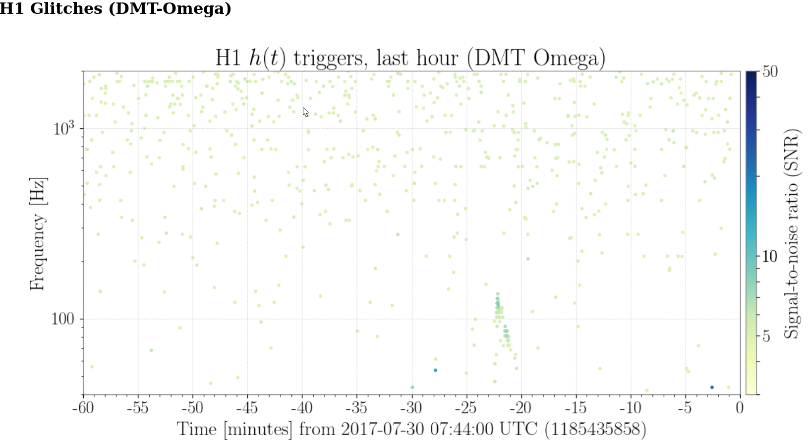
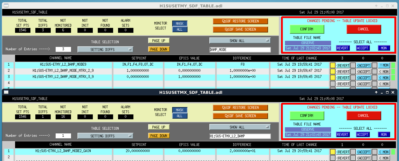
I used Conlog to find the violin mode damping filter settings at July 6 2017 06:00:00 UTC. According to the summary pages we were locked and in observing at that time. According to the USGS the 5.8 Montana earthquake occurred July 6 2017 06:30:17 UTC.
I have double checked the gains and degrees of freedom. It might be worth double checking the filters, as these were less straightforward to find.
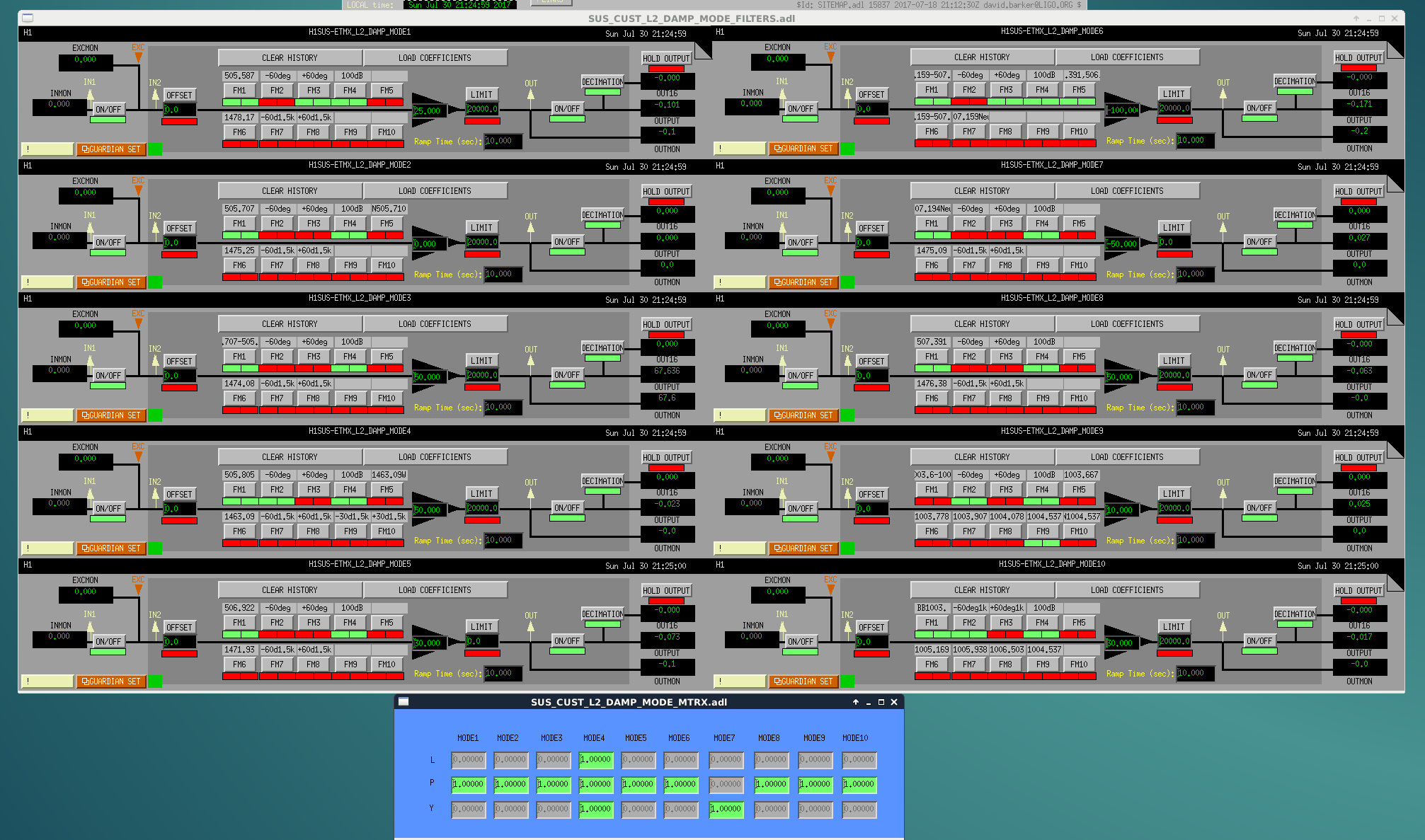
ETMX
Filters, Gain, DOF
Mode 1: 505.587 +60deg 100dB, +5, P
Mode 2: 505.707 +60deg 100dB, 0, P
Mode 3: 505.707-505.710 100dB, +10, P
Mode 4: 505.805 +60deg 100dB, -89.9315, P
Mode 5: 506.922 100dB, +3, P
Mode 6: 507.159-507.194 +60deg 100dB 'N507.391,506.922', -100, P
Mode 7: 507.194New +60deg 100dB, +15, P
Mode 8: 507.391 100dB, +5, P
Mode 9: -60deg 100dB 1004.537, +1, P
Mode 10: BB1003.6-1003.9 -60deg 100dB, +3, P
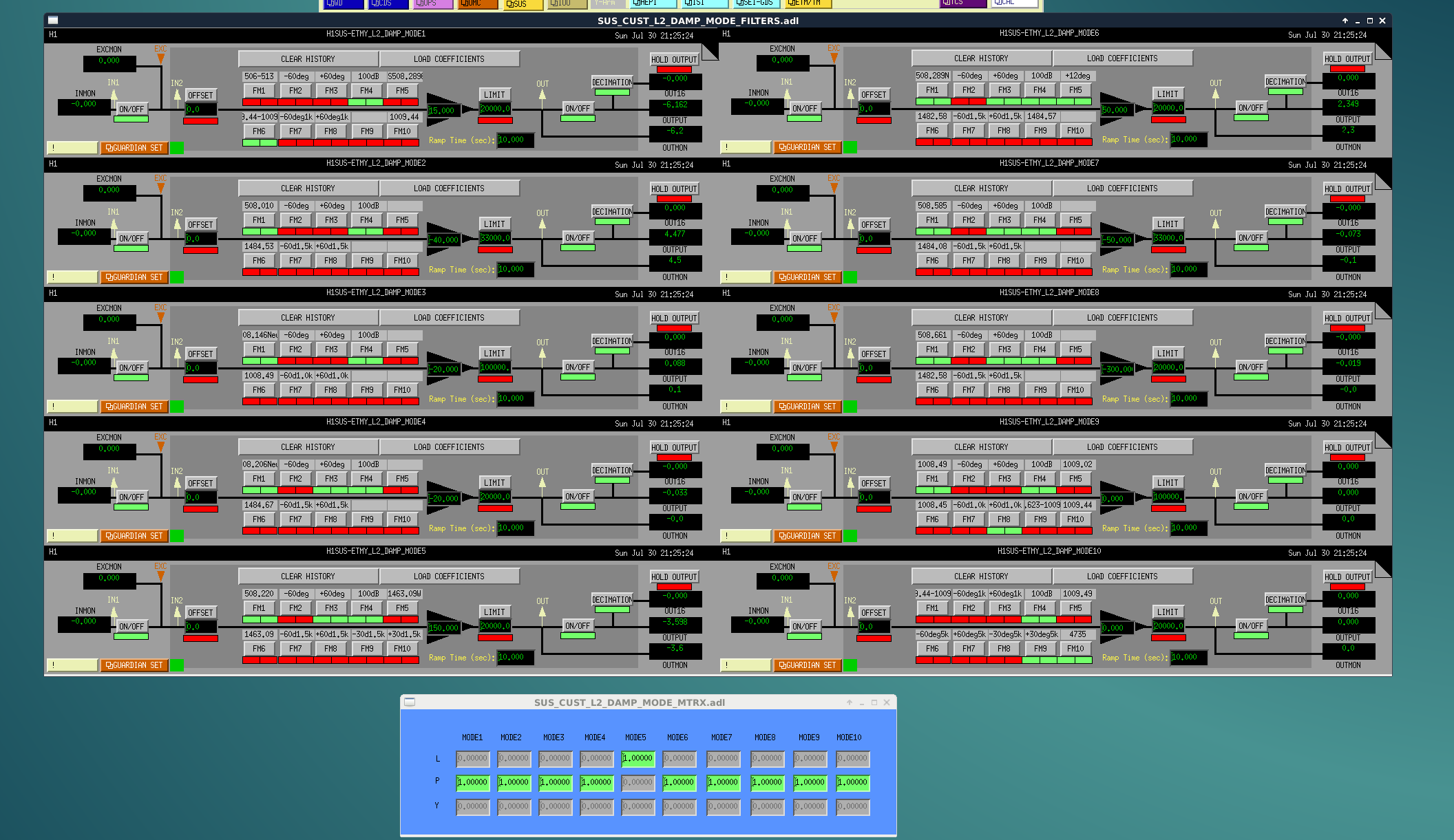
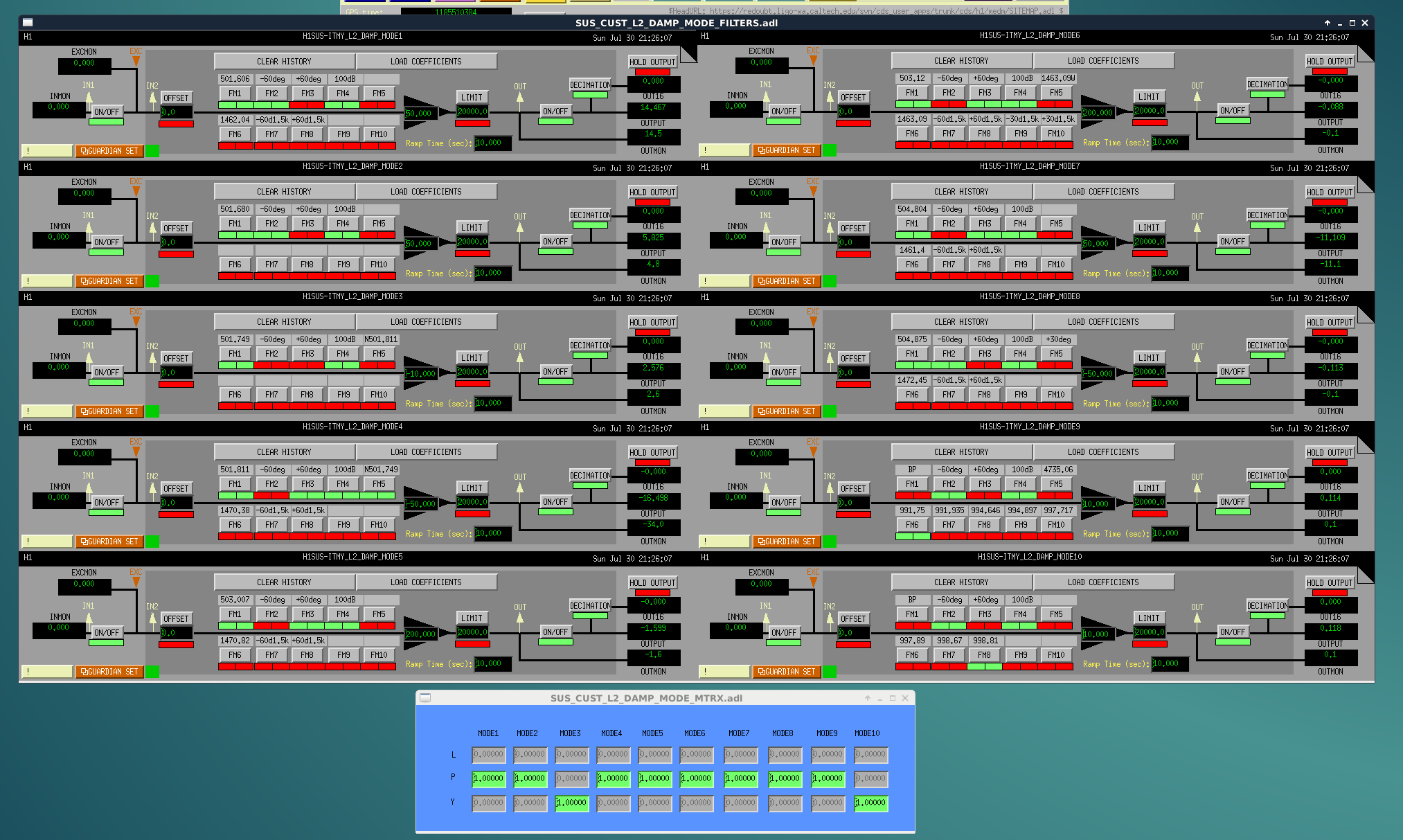
ETMY
Filters, Gain, DOF
Mode 1: 100dB 1009.44-1009.49, +15, P
Mode 2: 508.010 100dB, -40, P
Mode 3: 508.146New 100dB, -20, P
Mode 4: 508.206New +60deg 100dB, -20, P
Mode 5: 508.220 +60deg 100dB, -40, P
Mode 6: 508.289N +60deg 100dB +12deg, +500, P
Mode 7: 508.585 +60deg 100dB, -60, P
Mode 8: 508.661 +60deg 100dB, -500, P
Mode 9: -60deg 100dB 1009.02, 0, P
Mode 10: 100dB +30deg5k 4735, 0, P
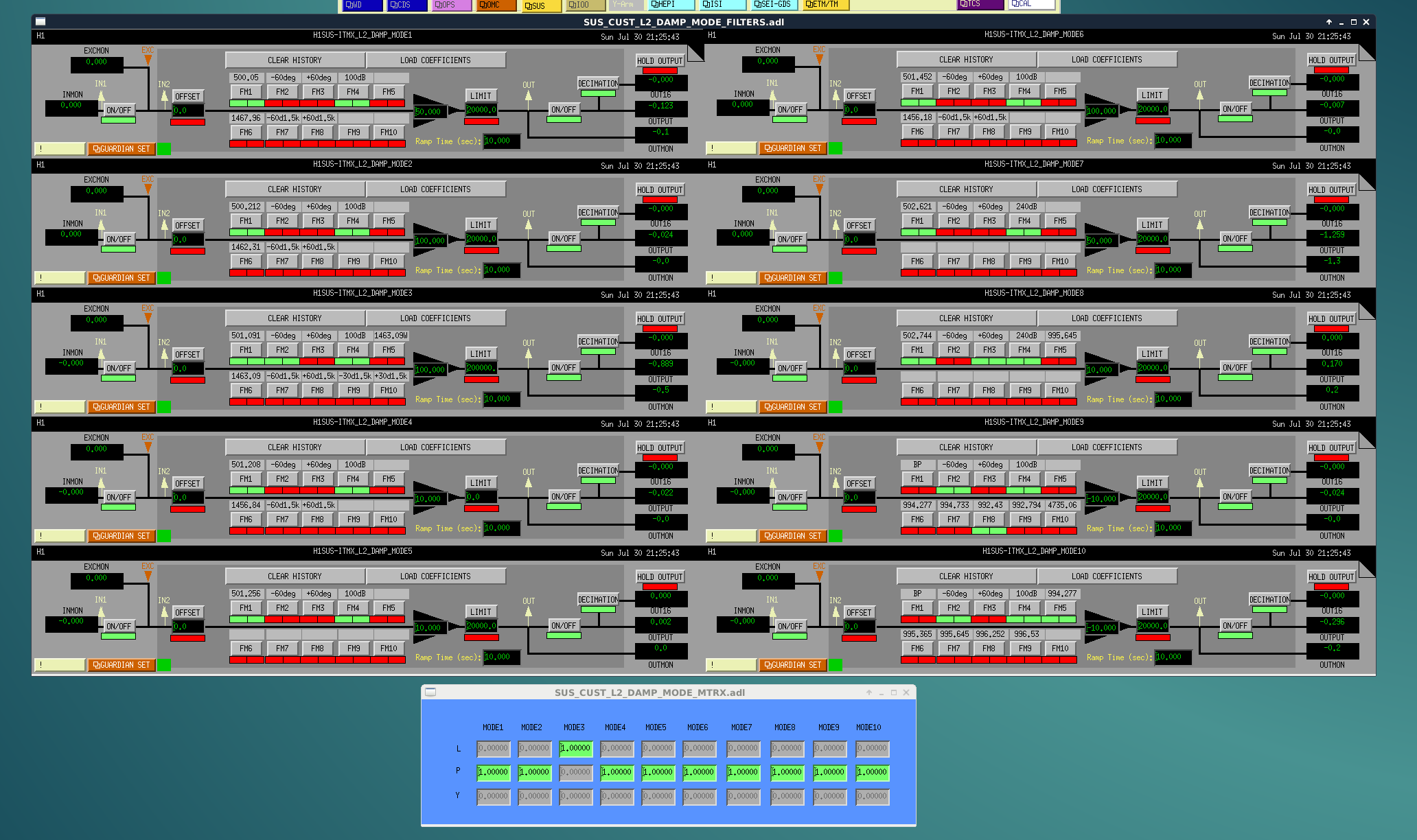
ITMX
Filters, Gain, DOF
Mode 1: 500.05 +60deg 100dB, +50, P
Mode 2: 500.212 100dB, +100, P
Mode 3: 501.091 -60deg 100dB, +100, P
Mode 4: 501.208 100dB, +10, P
Mode 5: 501.256 100dB, +100, P
Mode 6: 501.452 100dB, +100, P
Mode 7: 502.621 240dB, +50, P
Mode 8: 502.744 +60deg 240dB, +10, P
Mode 9: -60deg 100dB 992.43, -10, P
Mode 10: -60deg 100dB 994.277, -10, P
ITMY
Filters, Gain, DOF
Mode 1: 501.606 -60deg 100dB, +20, P
Mode 2: 501.680 -60deg 100dB, +200, P
Mode 3: 501.749 100dB, +200, P
Mode 4: 501.811 100dB N501.749, -100, P
Mode 5: 503.007 +60deg 100dB, +100, P
Mode 6: 503.12 -60deg 100dB, -20, P
Mode 7: 504.804 +60deg 100dB, +500, P
Mode 8: 504.875 -60deg 100dB, -50, P
Mode 9: -60deg 100dB 994.646, +10, P
Mode 10: -60deg 100dB 998.81, -10, P