J. Kissel
Albert asked me to describe the recovery from the Jul 5-6th 2017 Montana EQ for his upcoming LVC meeting LIGO status talk, so in doing so, to make sure I reported correct and citable information, I created a detailed timeline of the recovery.
I post it here, for the record, and in case it might jog some folks memory in figuring out some smoking gun for the new noise source.
%%%%%%%%%%%
Exec Summary:
We were able to return to nominal low noise within a day. We have problems with higher-than-1.0kHz harmonics (3rd harmonics at 1.5 kHz mostly) rung up for only a few days. We had problems with the automated damping of the 0.5 kHz and 1.0 kHz modes because of coupling changes and more EQs and HEPI Pump Failures, but only for about 8 days after the EQ. However, because a bunch of other problems, cancelled shifts from defeated employees, regular maintenance days, 2 weekends with only the operator on site, and broken scripts coupled with operator confusion, it wasn’t until Jul 19th 2017 (local), the Wednesday after maintenance (only 14 days after the July 5-6th 2017 EQ) that we recovered the new-normal sensitivity of ~55-60 Mpc. I back up this statement with a detailed timeline below for your perusal backed up with aLOG citations.
%%%%%%%%%%%
Detailed Timeline:
- Jul 6th 2017 6:31 UTC, (Last half hour of Eve Shift Wednesday local time) EQ Hits.
- Owl shift and Day shift Thursday morning (Jul 6th 2017) is spent recovering the SEI and SUS systems, and restoring alignment. LHO aLOG 37347
- We were able to recover ALS DIFF by mid-day Thursday, after hand-damping some Bounce and Roll modes. LHO aLOG 37357
- We we up to DC readout by the evening that evening (with no stages of DCPD whitening), but then one of the end station HEPI pump stations tripped. LHO aLOG 37359
- Jul 7th 2017 Once recovered, I worked on actively damping the 1.5 kHz 3rd harmonics for the first time that had rung up during the EQ. LHO aLOG 37361
These were the only modes new modes that were particularly problematic, and it was only a few of them, because their mode separation was in the ~mHz, and their coupling was week.
- Then the weekend hit, and operators were still relatively inexperienced in tuning violin mode damping. While they were mostly successful by skipping the automated damping, and slowing inching up the gain on the active damping, they’d still occasionally they’d ring up, as they do after any normal lock loss, but when they tried to adjust the settings things got more rung up; e.g. LHO aLOG 37394
- Jul 9 2017 at ~2 UTC on Travis’ eve shift, something went belly up as the range slowly decayed and the lock broke. LHO aLOG 37399
Since it was a “slow” lock loss, we were likely sending junk to all of the test masses for an extended period of time. That coupled with another EQ, LHO aLOG 37403, and high winds, 2017-07-10 Wind Summary Page, reverted all the hard work on violin modes, including some of the new 1.5 kHz modes. Upon recovery all modes had rung back up, and modes began to become unresponsive to normal settings, LHO aLOG 37402
- Monday Morning / Day shift (Jul 10 2017), we picked up focused efforts on new modes, and made sure no other modes went bad, LHO aLOG 37412 and LHO aLOG 37426. And by that evening (~8:00 pm local, when the A team left), we now had what we now now to be the new normal: LHO aLOG 37433 and we thought violin modes were under control.
- Then that night (Jul 10-11 2017) Patrick got his first exposure to what we’ve now found out later, that the coupling on some of the modes had changed (because of the Jul 6th EQ? because of the Jul 11th slow lock loss? Dunno.), and would now run away with time, LHO aLOG 37438. Not yet understanding that the mode coupling had changed, and coupled with more EQs and PSL trips due to continuing problems with flow sensors over night, meant we were dead, not debugging most of Monday Jun 11-12 UTC, and then we went into normal maintenance on Tuesday morning.
- Recovery after maintenance (Jul 11 2017) went OK, but because the fundamentals were rung up so high from the night before, we’d lose lock earlier in the lock acquisition sequence than normal. Confused and bewildered we cancelled 12 hours worth of shift; LHO aLOG 37467 and LHO aLOG 37468. We found out later that it was just another PD that was saturating from the now re-rung up violins, LHO aLOG 37500.
At this point I’ll emphasize — we were no longer having trouble with high order violin modes. It was that fundamental (~500 Hz) and 1st harmonic (1 kHz) “normal” damping wasn’t working. Further, we’re able to regularly get to reasonable sensitivity, we just didn’t hit the science mode button because we were still actively playing with violin mode damping filters to get them to work. It’s Wednesday Jul 12, so only 7 days after the EQ.
- Another HEPI Pump Trip at EX while the IFO was down likely rung the normal 0.5 and 1.0 kHz modes back up, LHO aLOG 37475
- Jul 12 2017 Wednesday, we begin to realize the normal automated damping isn’t working LHO aLOG 37484, but it was unclear which modes were going bad, over the next few shifts, we slowly and systematically checked the phase and gain of every loop, and updated the LHO Violin Mode Table and Guardian accordingly.
- The Beam Splitter CPS started glitching, for no known reasons, LHO aLOG 37499, which also decreased productivity.
- By Jul 13 2017 Thursday, 8 days after the EQ, we had re-configured all of the automated damping and quantified how many of the modes now had changed coupling, LHO aLOG 37504, and violin modes were no longer a problem.
The remainder of the time before we regularly went back to observing was spent exploring why the sensitivity was much worse, and/or other unrelated problems resulted in more defeated shift cancelling.
It was unrelated to any violin modes.
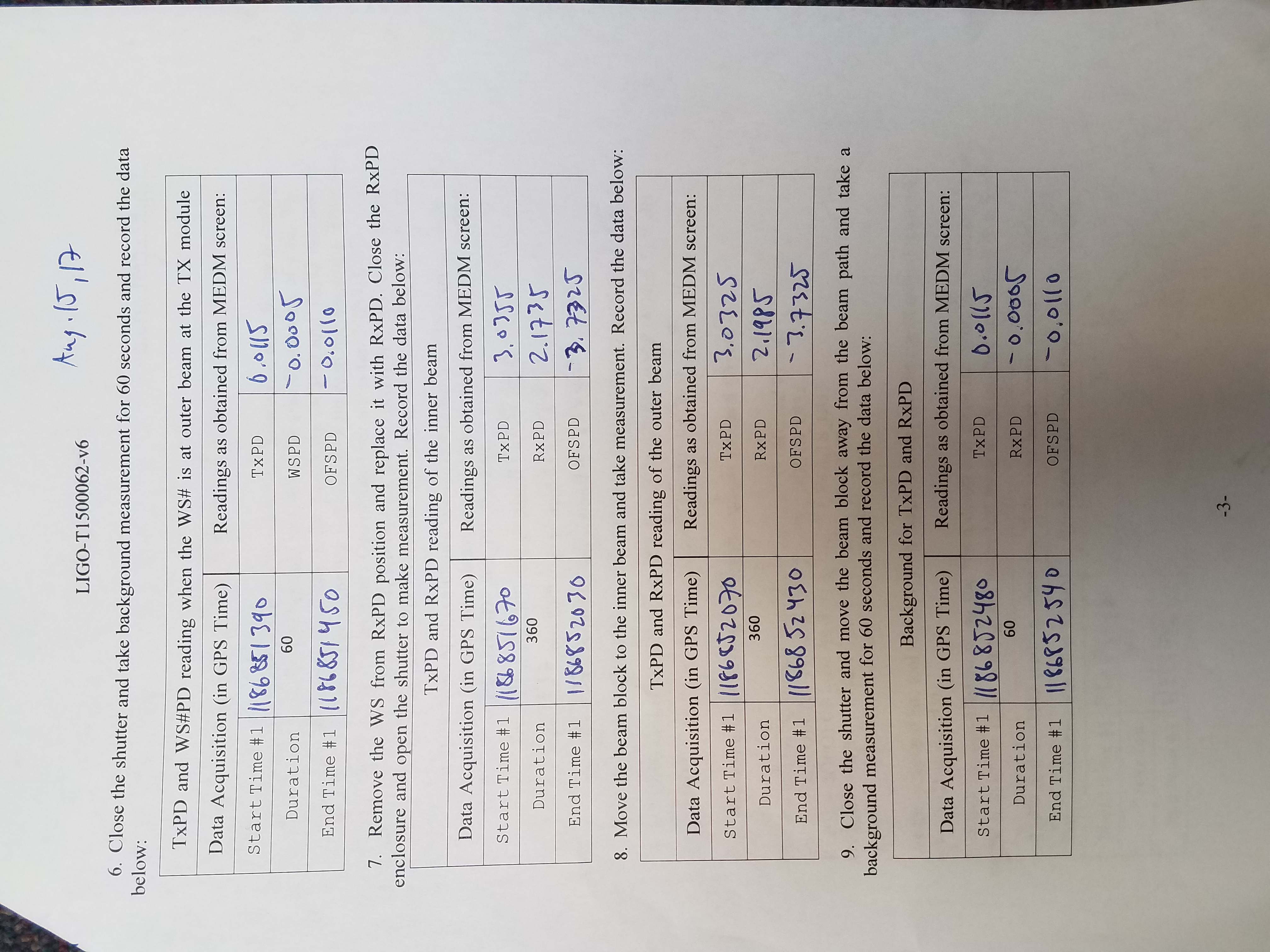
Spot position moves (LHO aLOG 37506 and LHO aLOG 37536)
Fast shutter problems (LHO aLOG 37553)
More PSL Trips (LHO aLOG 37560)
A broken script and a mis-calculated SDF accept left us on only one DCPD for a few days (LHO aLOG 37585)
etc.
And our sensitivity has not changed since then.
So I would say that, aside from this new mystery noise that we still don’t understand, we were fully recovered by Wednesday Jul 19th 2017, 14 days after the EQ.


Two attachments - DARM_a2l_passive: