travis.sadecki@LIGO.ORG - posted 02:33, Sunday 16 July 2017 - last comment - 03:55, Sunday 16 July 2017(37546)
Observing 9:33 UTC
Range is ~43 MPc.
Range is ~43 MPc.
TITLE: 07/16 Owl Shift: 07:00-15:00 UTC (00:00-08:00 PST), all times posted in UTC
STATE of H1: Lock Acquisition
OUTGOING OPERATOR: Cheryl
CURRENT ENVIRONMENT:
Wind: 18mph Gusts, 14mph 5min avg
Primary useism: 0.03 μm/s
Secondary useism: 0.05 μm/s
QUICK SUMMARY: Cheryl working on damping violin modes that rang up after last lockloss.
TITLE: 07/16 Eve Shift: 23:00-07:00 UTC (16:00-00:00 PST), all times posted in UTC
STATE of H1: Lock Acquisition
INCOMING OPERATOR: Travis
SHIFT SUMMARY:
LOG:
TITLE: 07/16 Eve Shift: 23:00-07:00 UTC (16:00-00:00 PST), all times posted in UTC
STATE of H1: Observing at 48Mpc
OUTGOING OPERATOR: Jim
CURRENT ENVIRONMENT:
Wind: 21mph Gusts, 17mph 5min avg
Primary useism: 0.05 μm/s
Secondary useism: 0.05 μm/s
QUICK SUMMARY: locked since last night
TITLE: 07/15 Day Shift: 15:00-23:00 UTC (08:00-16:00 PST), all times posted in UTC
STATE of H1: Observing at 48Mpc
INCOMING OPERATOR: Cheryl
SHIFT SUMMARY:
LOG:
21:00 Kyle on site working on VPW
CH2M was supposed to knock down a stack today. Didn't see any evidence of it here on ground sensors or roof cam, but wall FOMs may not include relevant frequency bands?
TITLE: 07/15 Owl Shift: 07:00-15:00 UTC (00:00-08:00 PST), all times posted in UTC
STATE of H1: Observing at 51Mpc
INCOMING OPERATOR: Jim
SHIFT SUMMARY: Observing for 4+ hours. No issues after IA and relocking.
LOG: None
After a bit of a extensive IA followed by a short lock, we are back to Observing. The range is down from earlier in the week at around 50 MPc.
TITLE: 07/15 Owl Shift: 07:00-15:00 UTC (00:00-08:00 PST), all times posted in UTC
STATE of H1: Calibration
OUTGOING OPERATOR: Cheryl
CURRENT ENVIRONMENT:
Wind: 8mph Gusts, 6mph 5min avg
Primary useism: 0.01 μm/s
Secondary useism: 0.06 μm/s
QUICK SUMMARY: Relocking after mystery lockloss post input pointing changes. Currently at DRMI_LOCKED and will attempt to proceed further. Cheryl suggests that if this lock doesn't work out, another IA may be helpful.
TITLE: 07/15 Eve Shift: 23:00-07:00 UTC (16:00-00:00 PST), all times posted in UTC
STATE of H1: Calibration
INCOMING OPERATOR: Travis
SHIFT SUMMARY:
LOG:
Jenne D. Thomas V.
After Robert finished his PEM injections, we wanted to try to change the pointing into the interferometer after IMC using the IM1 and IM3 to put IM4 Trans QPD back to the pre-EQ location, this seemed to help the range a bit as well as increase the power recycling gain.
Since we were convinced the pointing was satisfactory, we began to try to optimize the spot locations using the reverse A2L procedure using the June 18th data as a good reference. However, this really screwed up the sensitivity so we're leaving the SOFT loop offsets back at zero.
So in the end, there's a bit of change to the input pointing, spot positions remain unchanged, A2L gains remain unchanged.
TITLE: 07/15 Eve Shift: 23:00-07:00 UTC (16:00-00:00 PST), all times posted in UTC
STATE of H1: Calibration
OUTGOING OPERATOR: Corey
CURRENT ENVIRONMENT:
Wind: 5mph Gusts, 3mph 5min avg
Primary useism: 0.01 μm/s
Secondary useism: 0.07 μm/s
QUICK SUMMARY:
TITLE: 07/14 Day Shift: 15:00-23:00 UTC (08:00-16:00 PST), all times posted in UTC
STATE of H1: CALIBRATION ("PEM Injections")
INCOMING OPERATOR: Cheryl
SHIFT SUMMARY:
Violin Modes rung up while locking up! Please watch Violin Modes to confirm Guaridan settings are OK (watch them around the VIOLIN_MODE_DAMPING_1 steps).
LOG:
Since there are no tasks on deck for H1, going to take this opportunity to get some multiple-coincidence data (w/ L1 & V1).
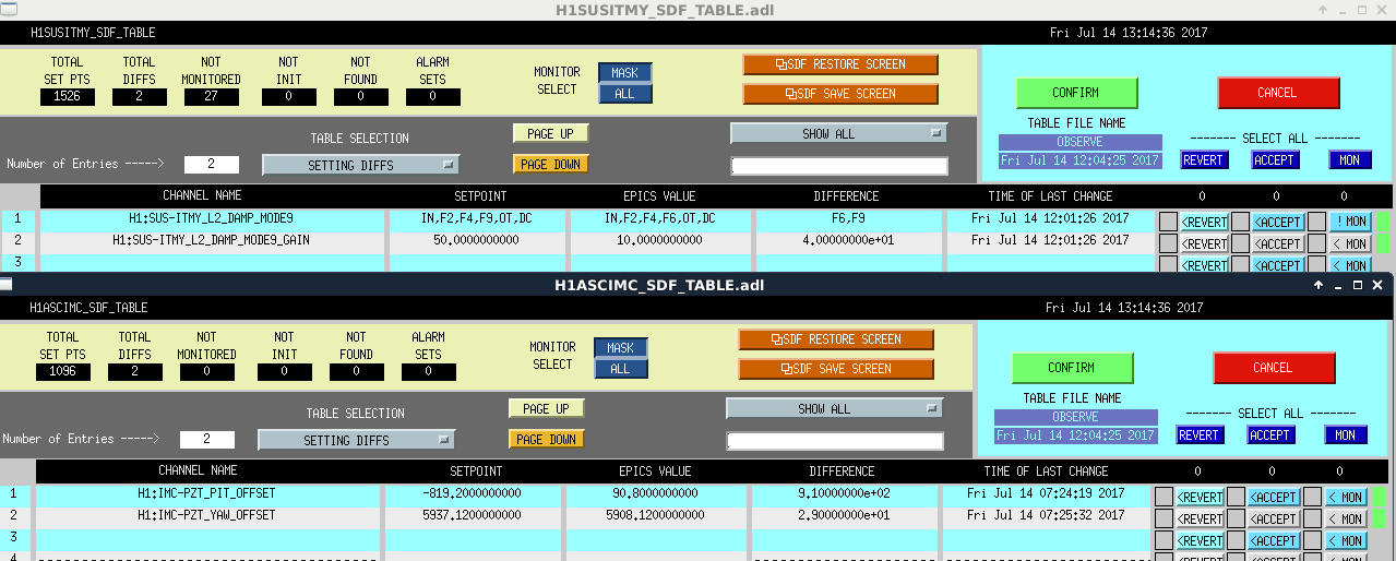
There were some SDF Diffs:
Guardian Note:
Since OMC_LOCK was needed to go to MANUAL to REMOVE_WHITENING,
I made two BruCo scans, the first from before the Montana EQ at:
https://ldas-jobs.ligo-wa.caltech.edu/~brian.oreilly/bruco_1183356018/
the second from July 14th 0300 UTC at:
https://ldas-jobs.ligo-wa.caltech.edu/~brian.oreilly/bruco_1184036418/
Attached are the trends of the Oplevs (FAMIS #4736).
Do not see any pressing issues to worry about.
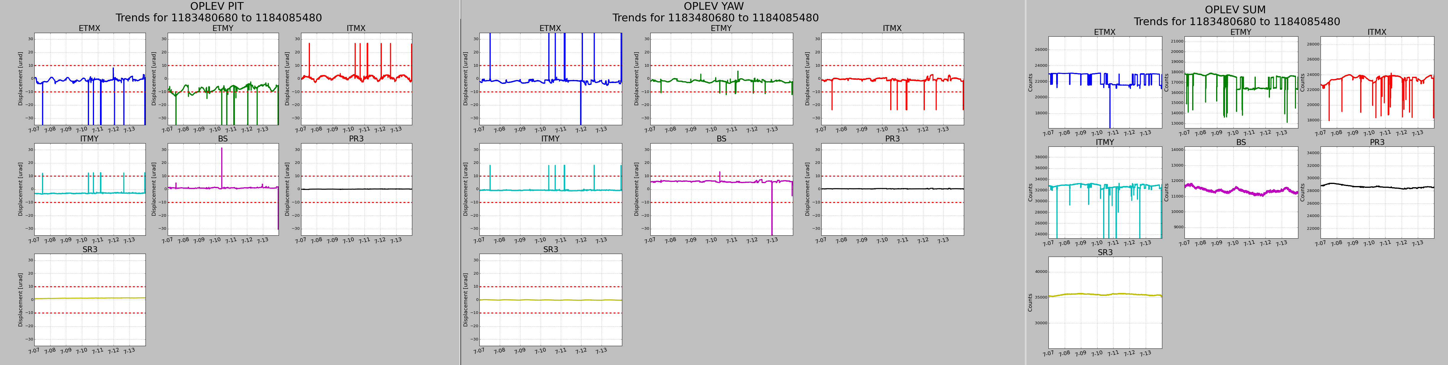
Agree with Corey, everything looks normal here.
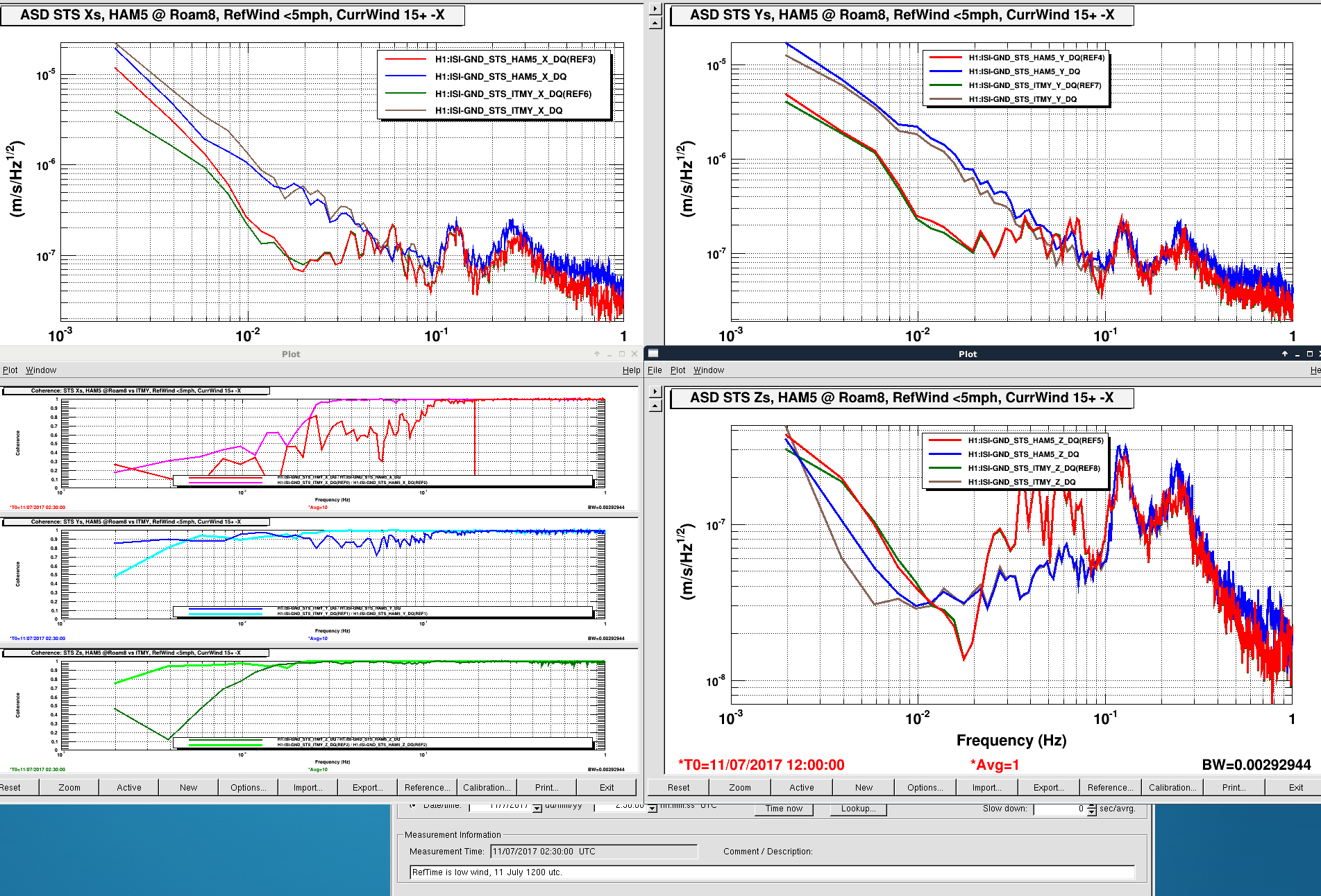
Last entry from Roam position 7, see 37334.
At Roam8, a meter or so further +X from Roam7, the spectra would suggest this location is not as quiet (wind response tilting) as Roam7. However, this wind is from the NNW rather than our usual S or SW for previous views. Also, while the Y dof seems more tilty for STS2-C (HAM5), at the lowest frequencies, HAM5 seems less tilty below 100mHz for the X dof. I'm not sure if this conclusion is valid when the sensor is noisier during the quiet period???
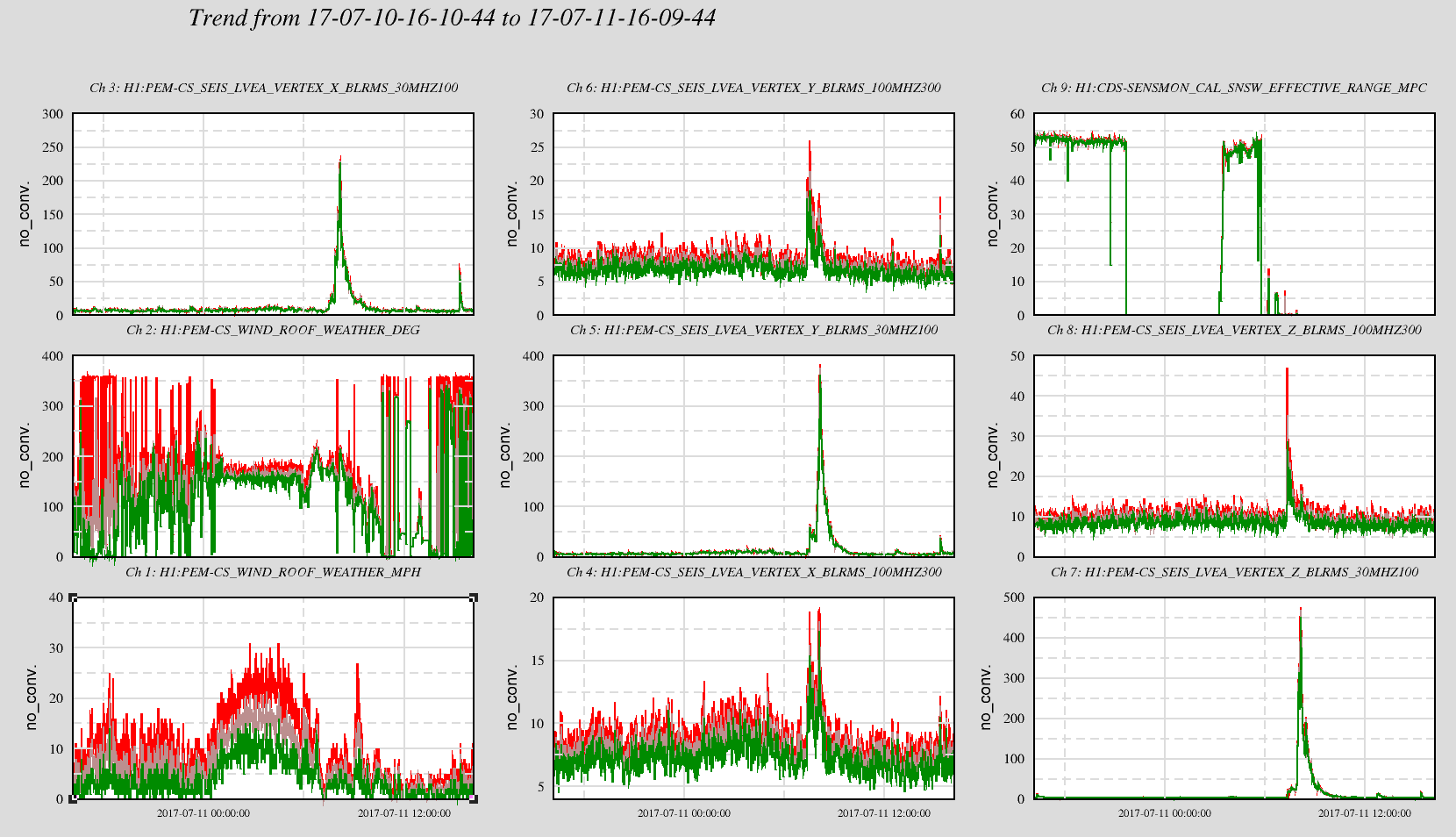
Attached are the usual wind plot and sensor spectra. The quiet wind time is 11 July 1200utc and the windy time begins 0230utc on 11 July.
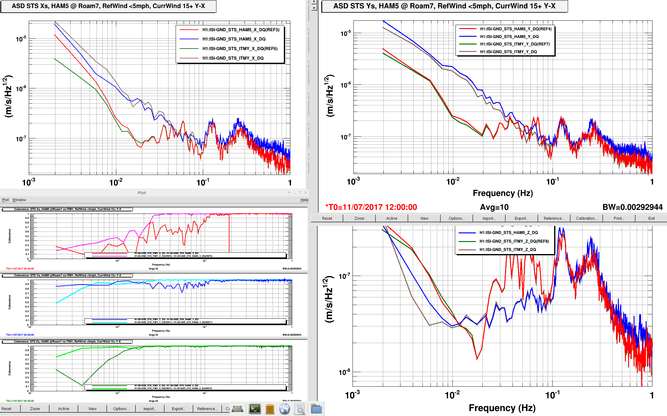
Correcting the above spectra plots. I forget to edit the titles of the plots indicating the location and wind details. These have been corrected and attached here.
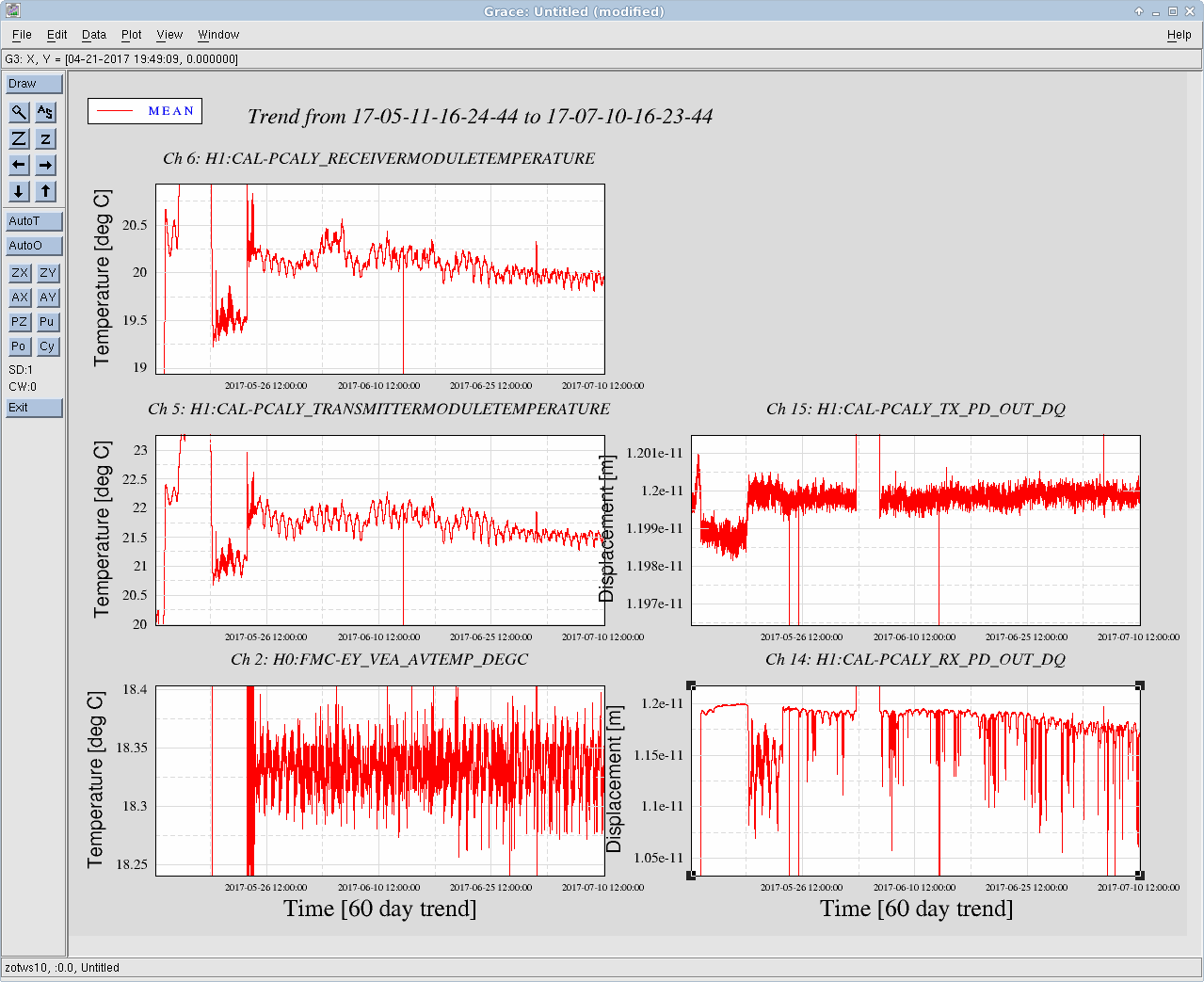
J. Kissel

Just posting an update on this -- the H1 PCAL Y RX PD reported displacement continues to decay, likely due to some temperature dependent clipping. This had been a part of the FRS Ticket 8328, but there's little we can do during an observation run to fix this. We've since closed the issue as LONGTERMFIX. AS such, I'll raise to an integration issue, and mark as WHEN VENT (similar to the promised work in Integration Issue 4700).

For now, recall that we've switched over to using TXPD as the calibration reference (see LHO aLOG 37166).
Opened IIET Ticket 8481
I've attached my related notes on this subject, as I've been trying to draw up a history of the issue since the Fall.

"Issue History.pdf" is the information I've been able to drag out of aLOGs and long time series, "Investigations.pdf" are the questions I've had and a select few I've answered. Apologies for the rambling nature, these are my personal notes.

Short summary of my investigations: temperature correlation on the Rx side is quite clear but higher frequency coherences appear to be only in obvious places (other PCalY OFS and Tx channels, ETMY ISI channels) and I haven't figured out how to measure coherence for long term, slow frequency signals.
Further investigations and notes will now exist in DCC document G1701350 (see https://dcc.ligo.org/G1701350).

Lockloss 9:38 UTC. DHARD loops seemed to be ringing up. ISC_LOCK guardian went into error upon lockloss. It was reporting an issue with OMC_LOCK not being managed, which turned out to be true. I INIT'ed ISC_LOCK. Going to run through an IA to see if it helps the DARM spectrum which was elevated across the entire frequency range.
Back to Observing at 10:54 UTC. DARM spectrum is still elevated at all frequencies. IA did not appear to help. Range is 46 MPc.