edmond.merilh@LIGO.ORG - posted 12:10, Tuesday 01 August 2017 (37944)
LVEA Sweep - Post Maintenance
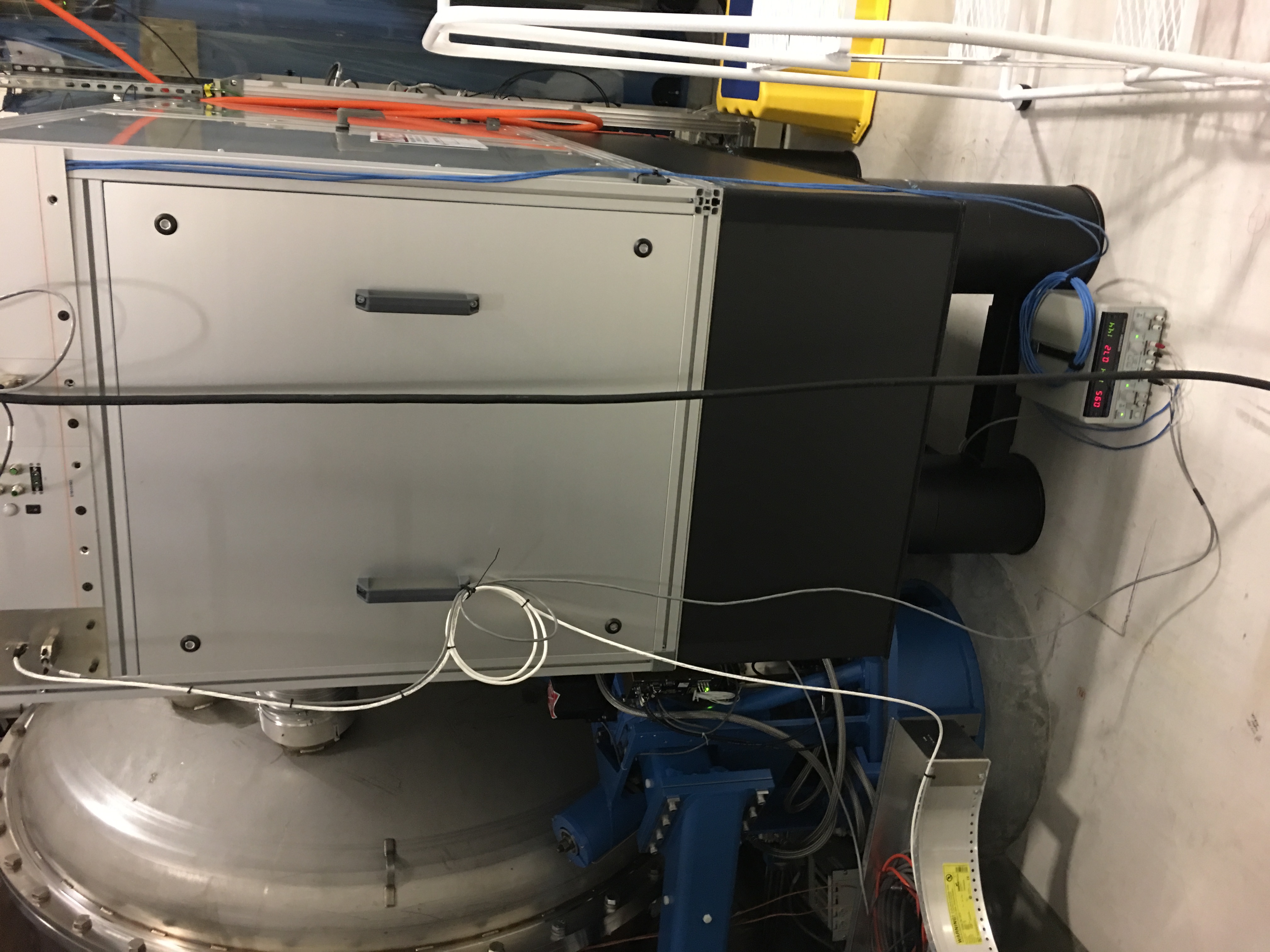
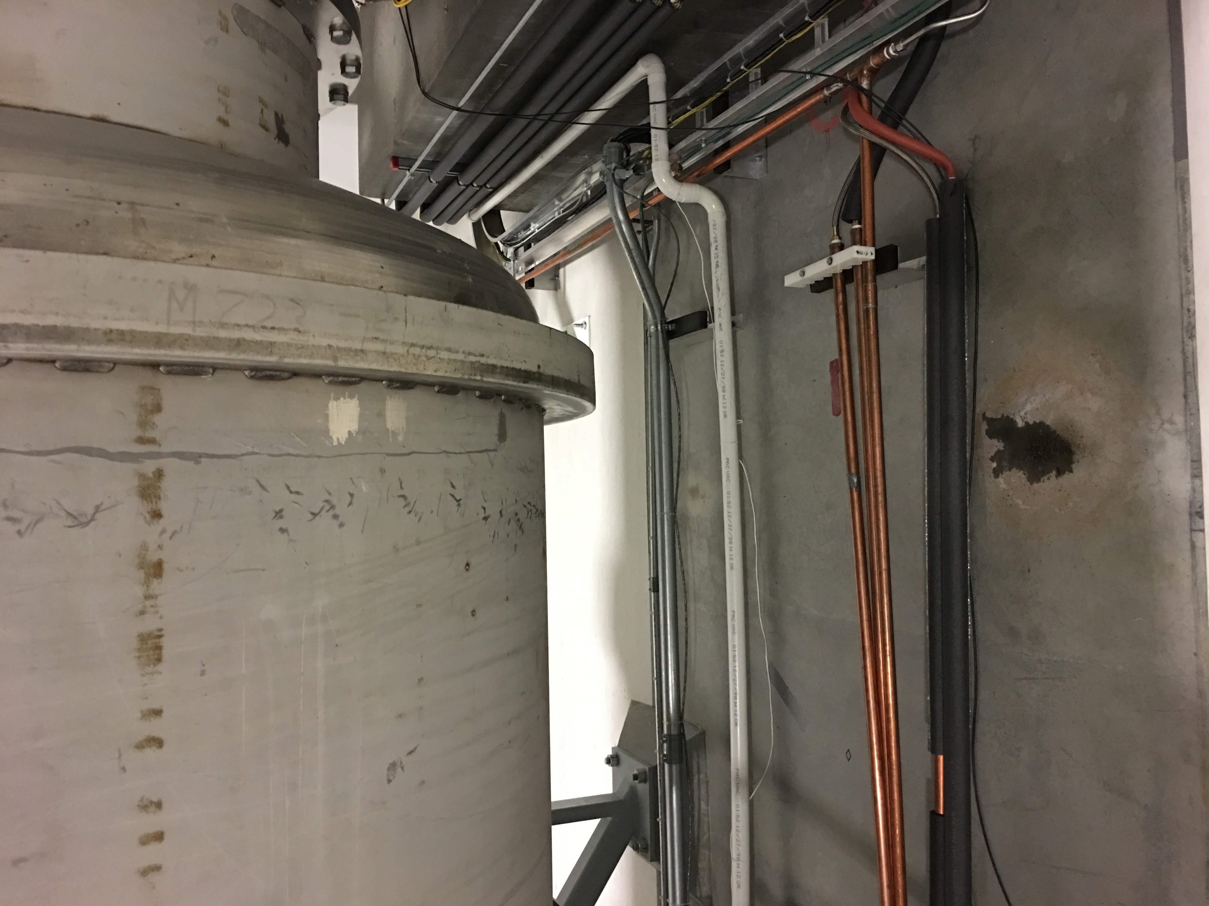
THe LVEA was swept in accordance with LIGO-T1500386v7. There was the usual whirring of fans in the vacuum rack, from a bench-type power supply on the floor at TCSX table and rather noticeably through the wall from the CER/High Bay area. I noticed some condensation dripping from CP1 and forming a little puddle on the floor.
Images attached to this report