edmond.merilh@LIGO.ORG - posted 23:51, Thursday 08 June 2017 (36748)
Shift Summary - Eve
TITLE: 06/09 Eve Shift: 23:00-07:00 UTC (16:00-00:00 PST), all times posted in UTC
STATE of H1: Observing at 65Mpc
INCOMING OPERATOR:Patrick
SHIFT SUMMARY:
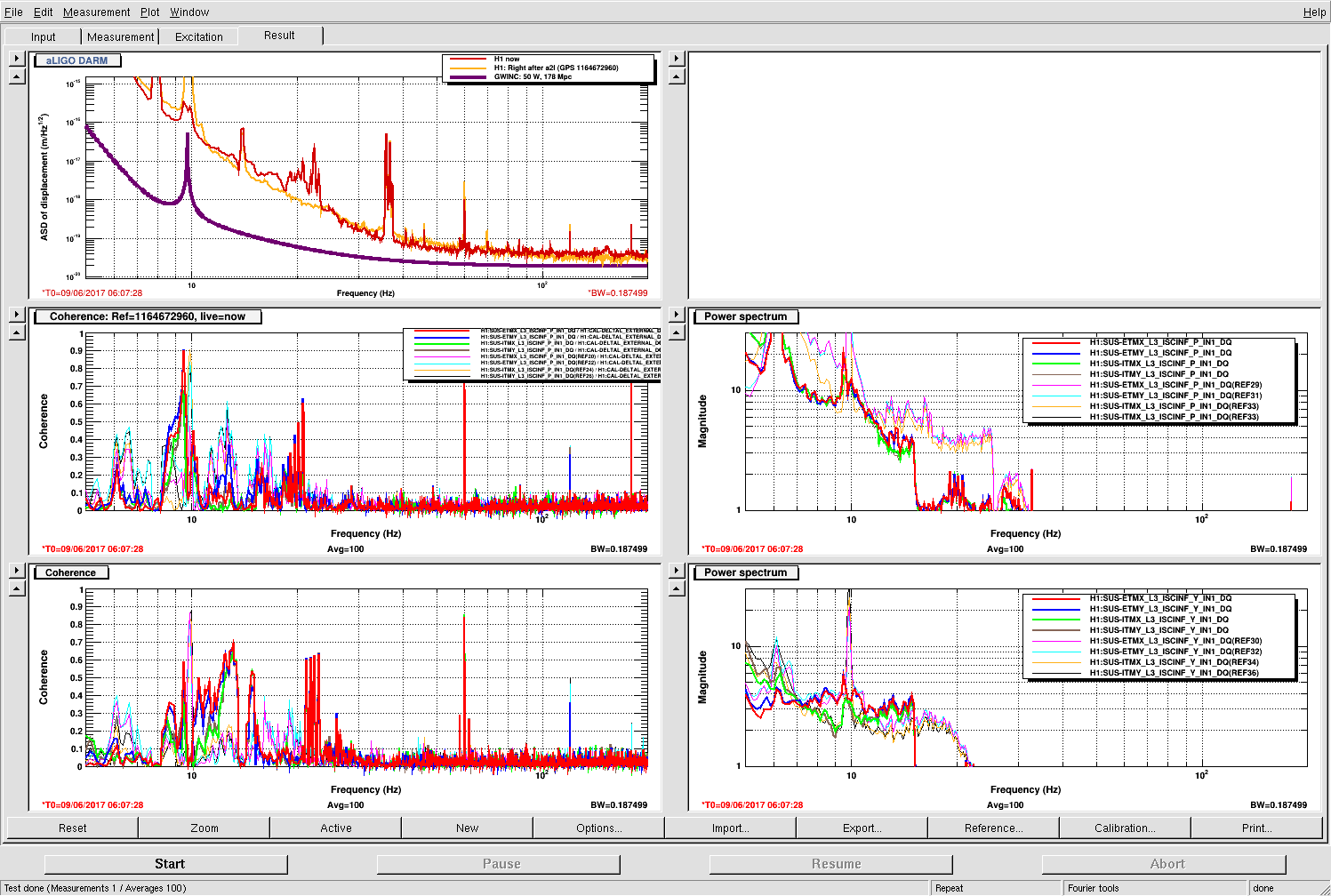
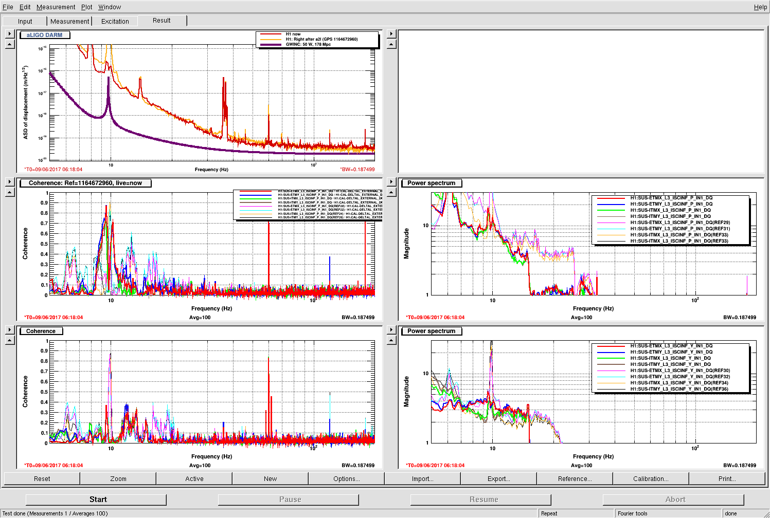
Quiet shift. There were a couple of small quakes that were of no consequence to H1. A2L was run towards the end of the shift as Livingston dropped their lock. Handing of locked/Observing H1 to Patrick. There was 1 RO alarm.
LOG:
23:10 Chandra to MY
23:23 Kyle called to inform me that he had driven past the barricade to the bunker with the pickup truck for gas cylinders.
23:25 Little Quake from around the Mariana Islands ~.05um
23:53 Chandra back
00:17 Wind is picking up in excess of 30mph over the last hour.