kiwamu.izumi@LIGO.ORG - posted 17:21, Friday 02 June 2017 - last comment - 18:15, Friday 02 June 2017(36629)
Update on ALS Y issue
Fil, Daniel, Jenne, Keita, Patrick, Richard, Sheila, Kiwamu,
The investigation continues. No solid conclusion or resolution yet.
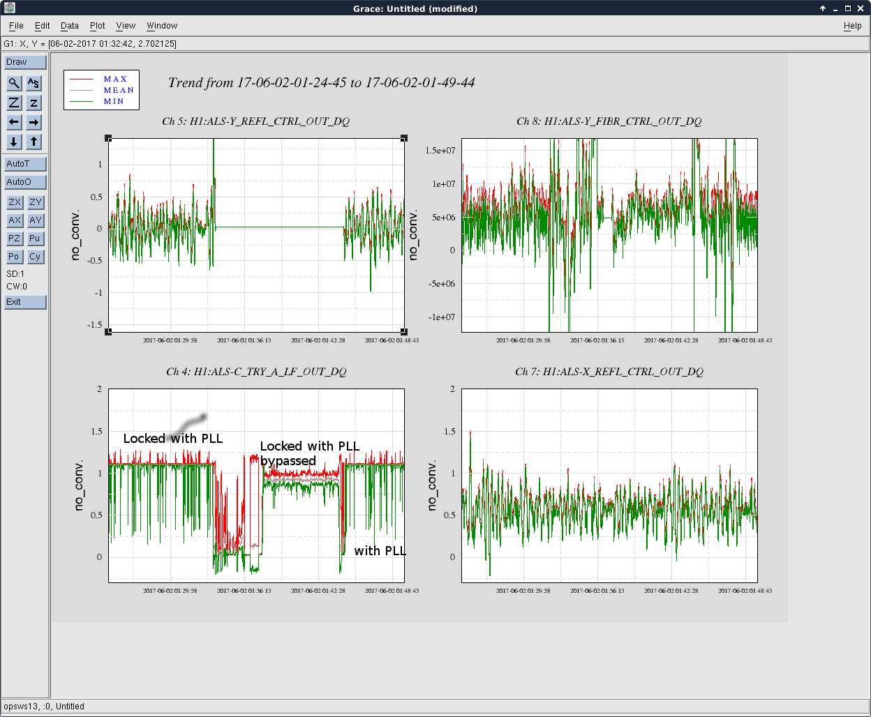
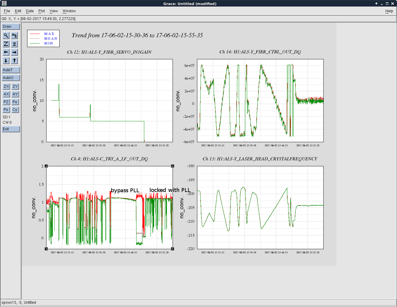
- We tried locking the laser to the Y arm by only using the PDH servo board in order to test the PDH board.
- The output of the PDH board was connected to the cable which is nominally connected to the output of the PLL board for this test operation.
- The same filter settings as usual but with a lower gain (I had to lower the fast path gain as well).
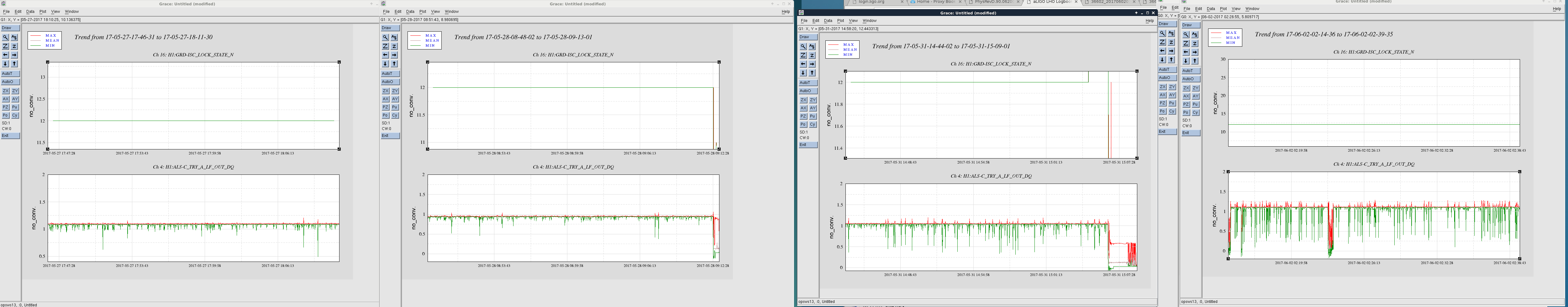
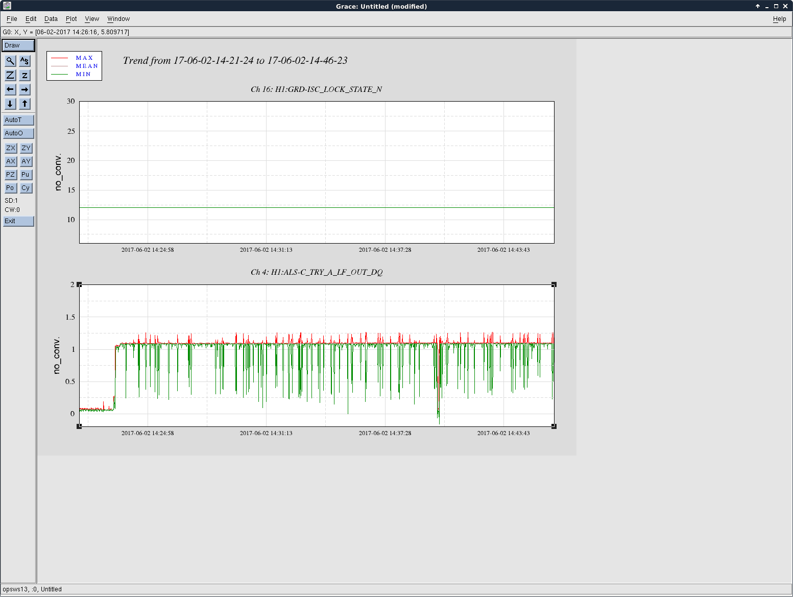
- This locked the laser somewhat but kept unlocking roughly every 10 sec. Note that this behavior is different from the glitches we have seen recently.
- It is inconclusive to say whether the PDH board is to blame for the glitches.
- Regardless of whether the PDH board is the culprit, we decided to swap the board.
- See 36622.
- The first replacement unit turned out to be not working (non funzione in Italian) because it didn't responds to changes in the remote offset adjusters.
- Fil then installed another spare unit with which we were able to control the electronic offset using the MEDM sliders.
- We then found that the FET demodulator gave us a big offset.
- We drove to the end station and then determined that the demodulator unit was non funzione either. The I-signal was just flat 5 V.
- We switched the system to the second half of the same demodulator unit.
- Now we are waiting for the Alaskan earthquake (LLO 34072) to settle so that we can test out the new PDH board.

Just to summarize what we think we know so far:
Things that were exonerated by bypassing PLL test:
Other things that we think are exonerated:
Things that we haven't eliminated: