jeffrey.kissel@LIGO.ORG - posted 20:44, Tuesday 30 May 2017 - last comment - 21:58, Tuesday 30 May 2017(36546)
What happened to the CARM/IMC Gain?
J. Kissel, S. Dwyer

Looking into why we have such high frequency noise coupling about a few kHz, we re-measured the CARM UGF (with and without IMC Boost Filter that comes on before nominal low noise) and IMC UGF (with the boost OFF), and found both loops with a factor of 2 less gain than we expect, at 7 kHz and 26 kHz respectively.

See attached transfer functions.

For reference,
- just a few days ago, Kiwamu suggests that the IMC loop gain was at it's normally high ~50 kHz in LHO aLOG 36354.
- I expect the current design similar from when Chris Whittle fully characterized the loop LHO aLOG 29735.
- The only difference we expect is this "new" boost, which we started using in Oct 2016; see LHO aLOG 30549.

The investigation continues...
Non-image files attached to this report

Comments related to this report
I attach the raw measurement data and the script I used to make the above plots.

SCRN0005.txt -- No IMC Boost CARM OLGTF Magnitude (in [dB])
SCRN0006.txt -- No IMC Boost CARM OLGTF Phase (in [deg])

SCRN0007.txt -- With IMC Boost CARM OLGTF Magnitude (in [dB])
SCRN0008.txt -- With IMC Boost CARM OLGTF Phase (in [deg])

SCRN0009.txt -- No Boost IMC OLGTF Magnitude (in [dB])
SCRN0010.txt -- No Boost IMC OLGTF Phase (in [deg])

Apologies for the arcane file format, the one GPIB setup has stopped working.
Non-image files attached to this comment


Jenne Patrick Sheila
- I went to the floor and measured the peak to peak value of the IMC PDH signal at out1, with the in1 slider set to 16dB, and saw 2.1Vpp (you can compare to 30549, where I measured 2.4Vpp).
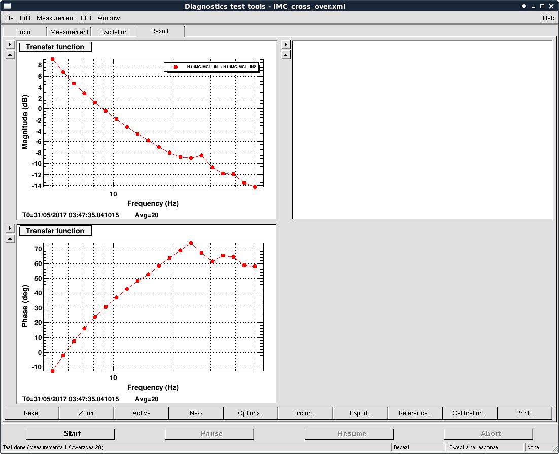
- We also measured the cross over between the MC2 path and the laser path, and saw that is also in good agreement with an old measurement. (attached)
- At a loss, we re-measured the IMC OLG and saw that the ugf was 49 kHz, very similar to what we expect, and a factor of 2 larger than Jeff's measurement....
I'm not sure what happened, but right now the IMC gain seems fine.
Images attached to this comment
Non-image files attached to this comment


