hugh.radkins@LIGO.ORG - posted 10:33, Friday 26 May 2017 (36443)
LHO LVEA Tilt Studies at Roam4--With wind from S (-Y +X)
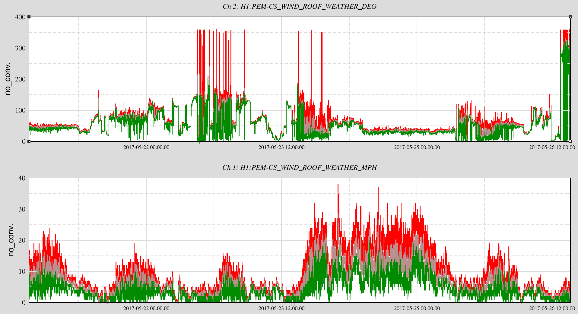
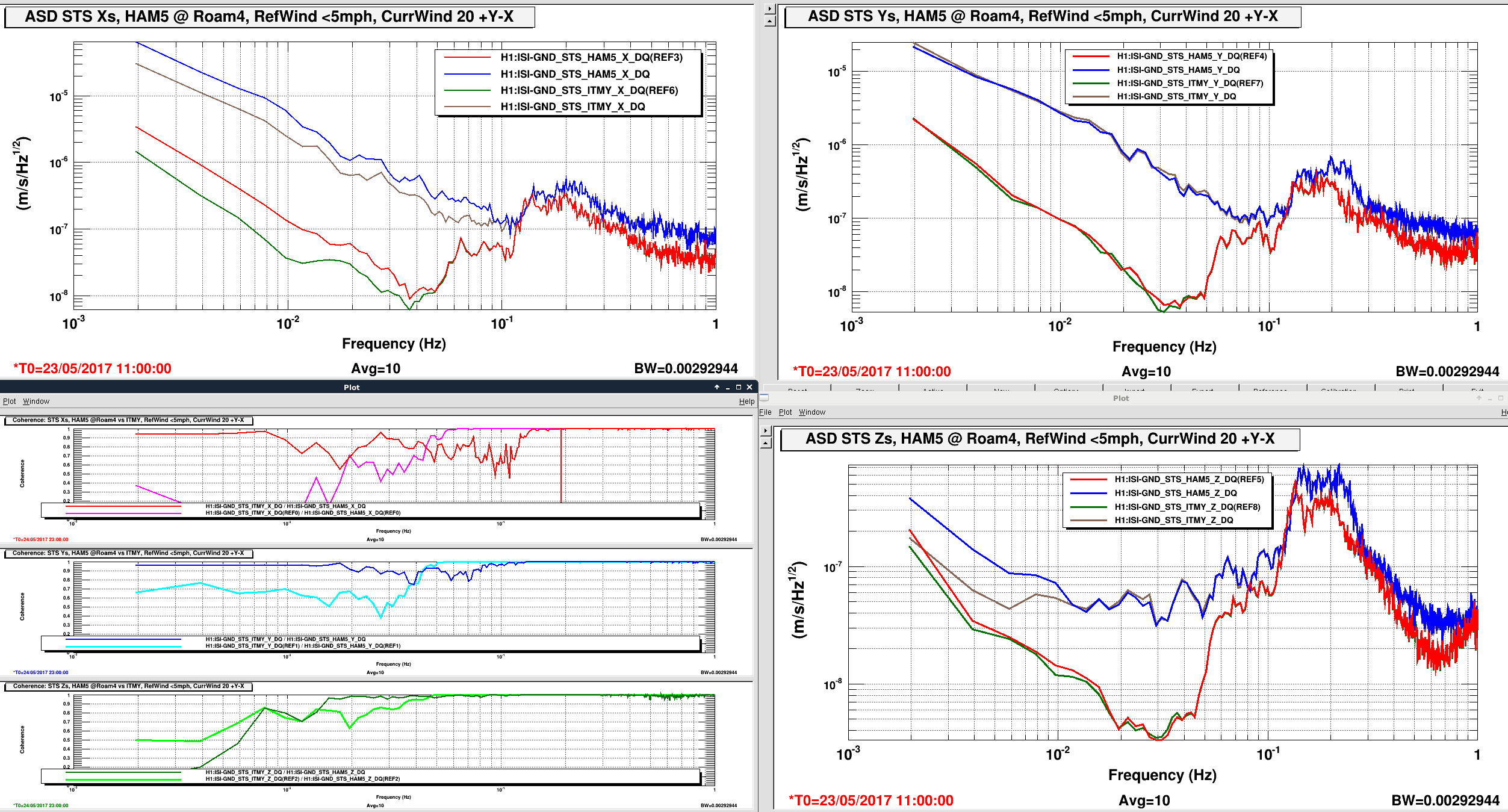
Moved the Seismometer a couple meters ~9 days ago. Attached are similar plots to previous looks of the ground motion in quiet and windy periods. The quiet time is 23 May at 1100utc and the windy period is 24 May at 2300utc. Not a great difference here compared to the Roam3 position, 35938, about 2 meters +Y from this Roam4 location. I might could argue that the Roam4 location shows a bit less increase in the X dof below 20mHz but this is too subtle to be significant. Bottom line, again, another location not as quiet as ITMY, during windy periods.
The attached plots show the CS wind velocity and the coherence/ASDs of the Roaming instrument (HAM5) and the ITMY.
Images attached to this report