travis.sadecki@LIGO.ORG - posted 08:20, Thursday 02 March 2017 (34531)
Observing at 16:20 UTC
A2L is complete. Back to Observing.
A2L is complete. Back to Observing.
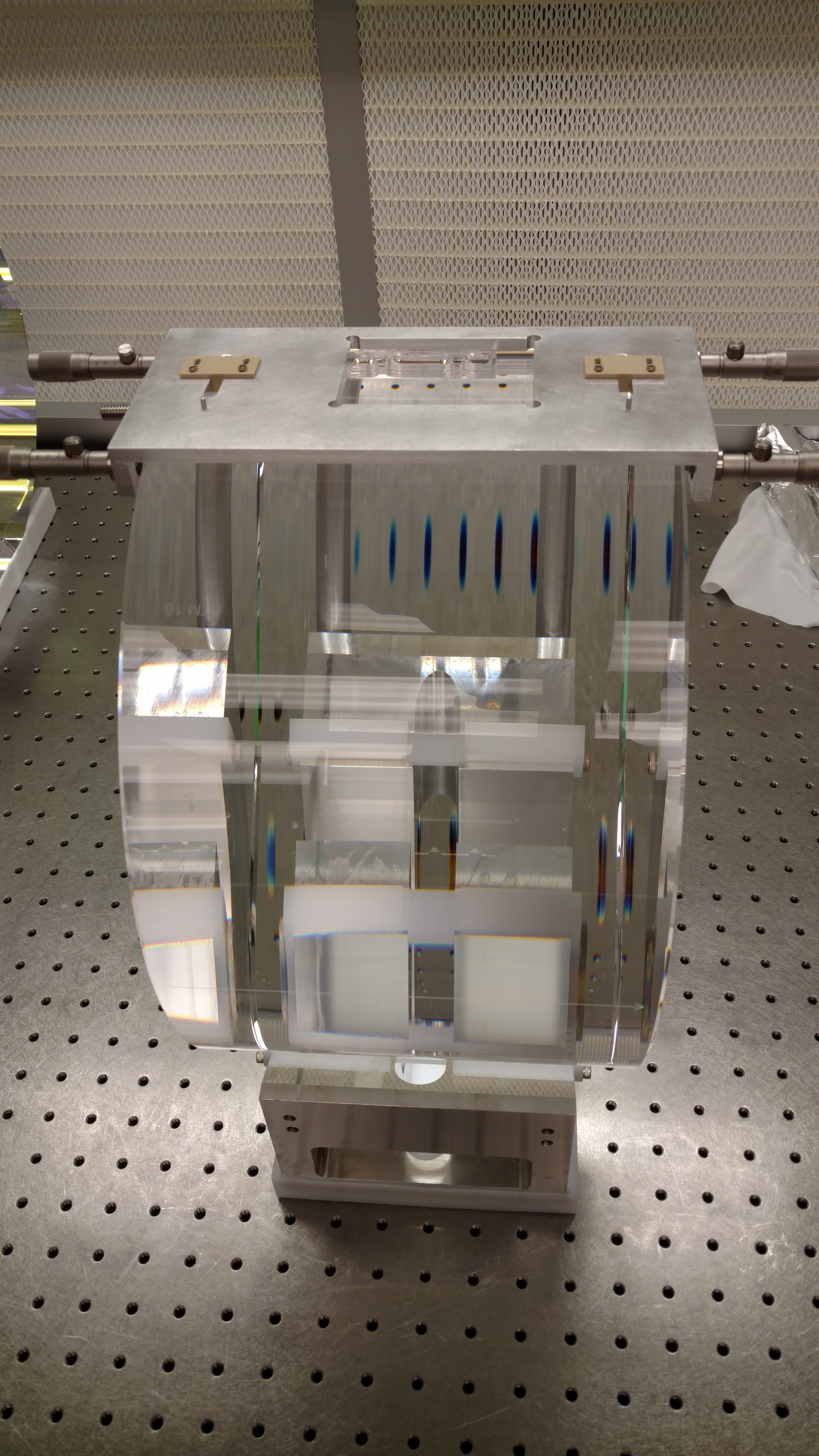
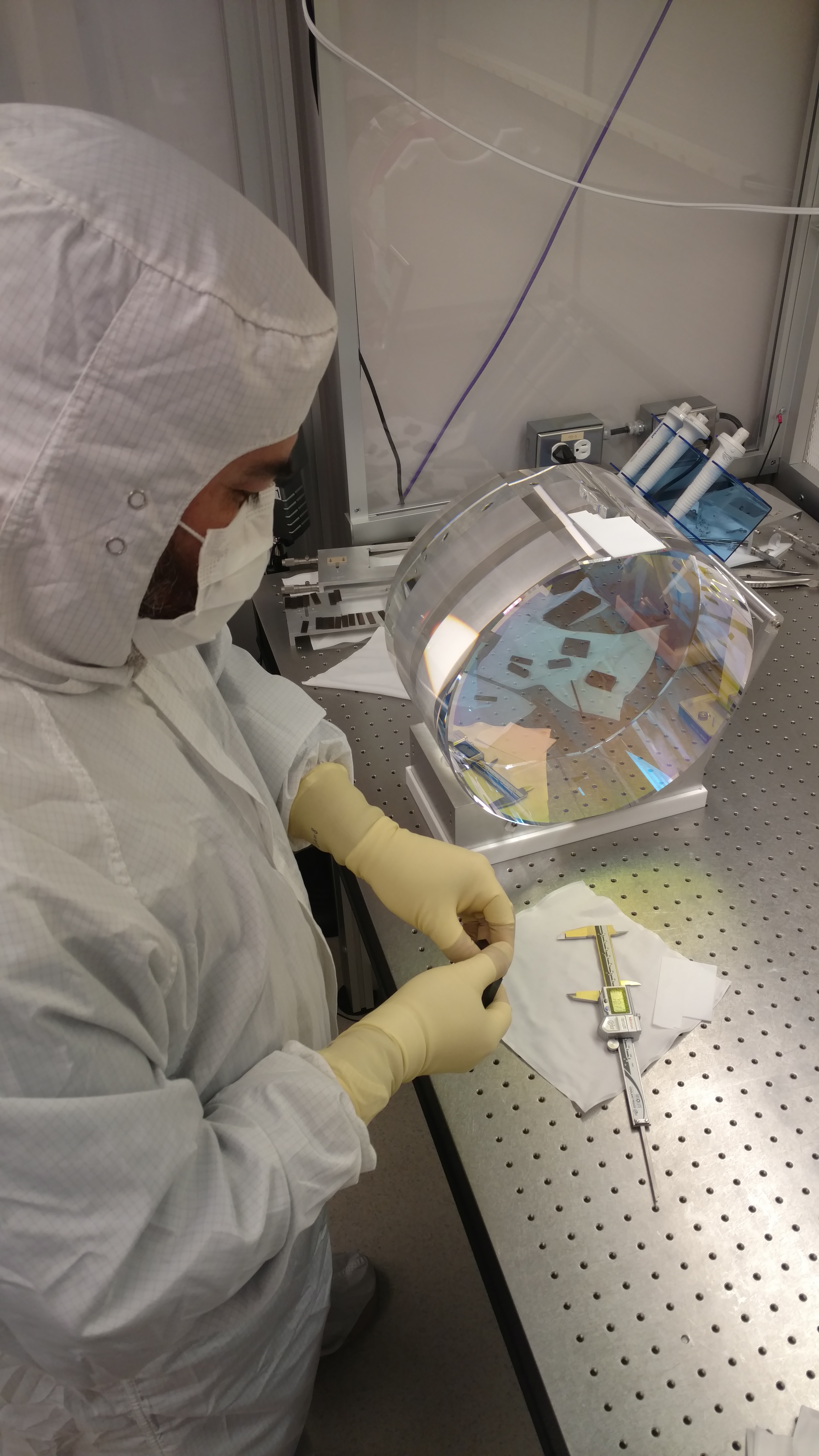
Cruising along from the successful ear bond on Tuesday, Gerardo and I plowed through 2 more successful ear bonds yesterday! We finished the second ear bond on the ETM13 S3 flat with ear 114, and also the first of the 2 ears for ETM16 - S4 flat now has ear 178 bonded. These new ear bonds are as good as the one from yesterday - very small error in location which is well under spec, and hardly any bubbles or features. So, the new ETMx is finished, and we are half way done with the new ETMy. 3 ears down, 1 to go.
Running A2L while LLO is down.
TITLE: 03/02 Day Shift: 16:00-00:00 UTC (08:00-16:00 PST), all times posted in UTC
STATE of H1: Preventative Maintenance
OUTGOING OPERATOR: Jeff
CURRENT ENVIRONMENT:
Wind: 3mph Gusts, 2mph 5min avg
Primary useism: 0.02 μm/s
Secondary useism: 0.23 μm/s
QUICK SUMMARY: Locked in Observe for 8+ hours upon arrival.
Shift Summary: A quiet Owl Observing shift. Range was suppress due to the Breathing Noise. This appears to have been relieved by turning off the main fire pump; left running after the HFD was on site during maintenance. Range is now back up in the mid to upper 60s Mpc. There was one EQ in Turkey this morning, which did not perturb LHO. No other issues or problems.
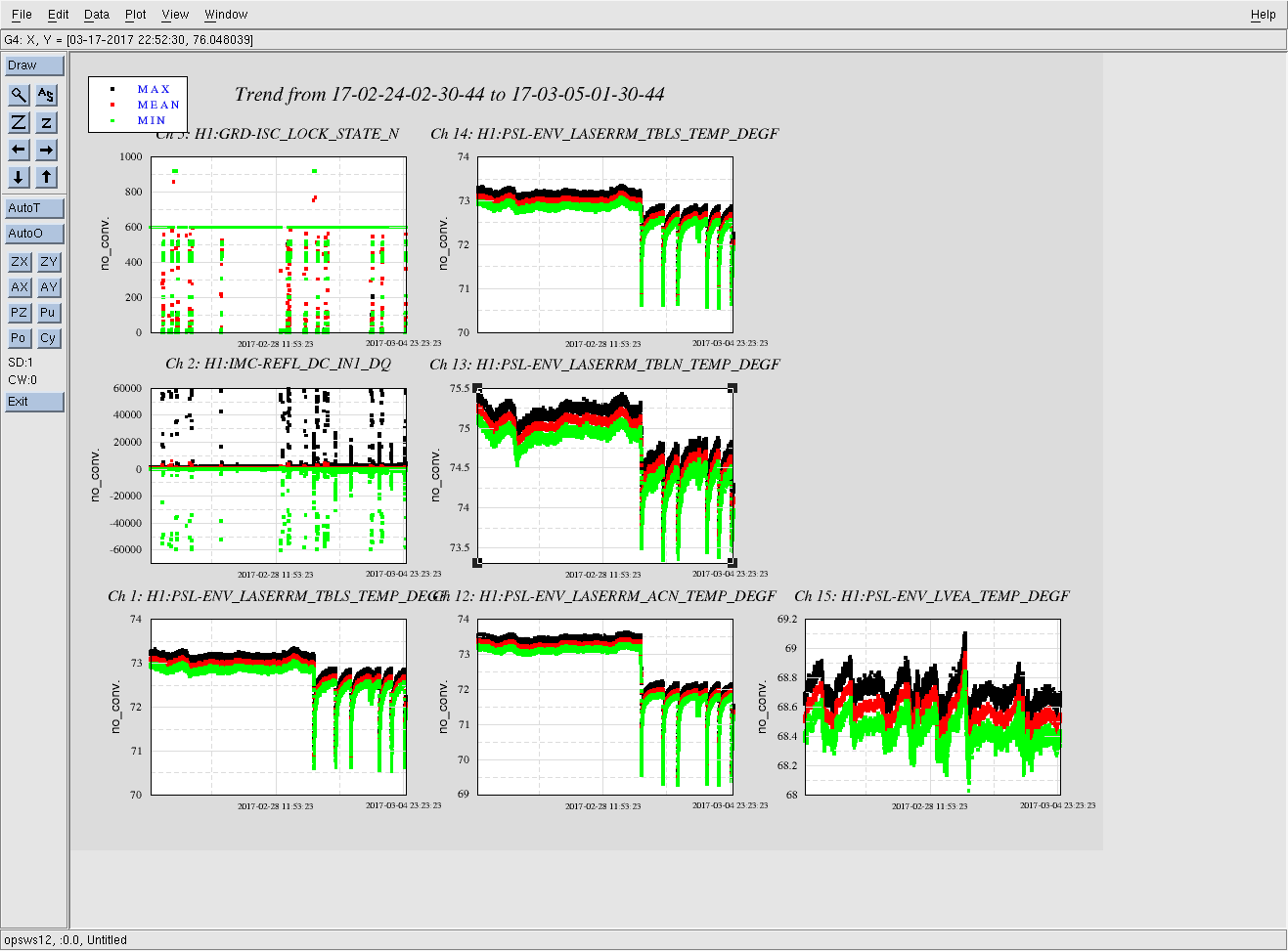
At 14:19 (06:19) received alarm that PSL A/C was on or Low Temp in Laser Room. The PSL South temp is 69f, the PSL North temp is 70F. The PSL Table North is 73f. The PSL Table South is 71F. The Dust Monitor #101 under the table is reporting 69f.
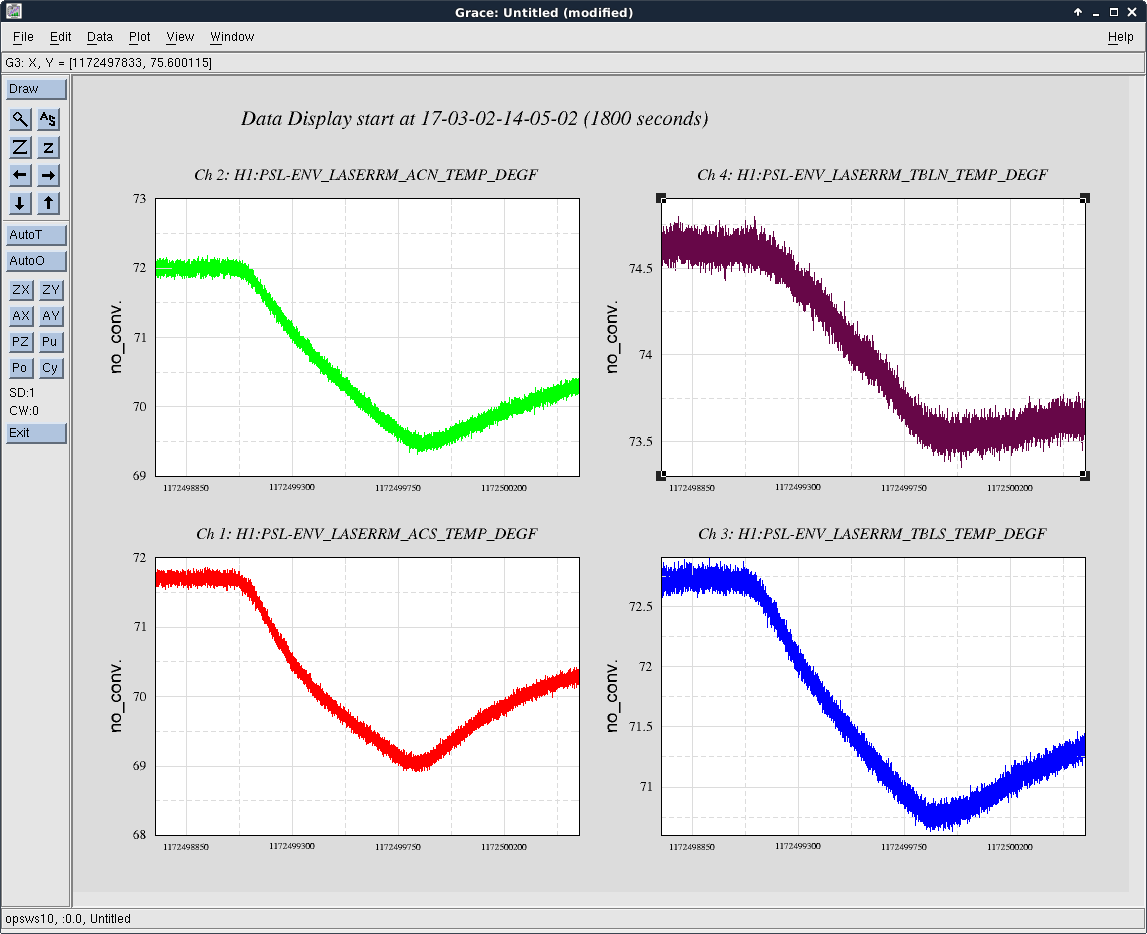
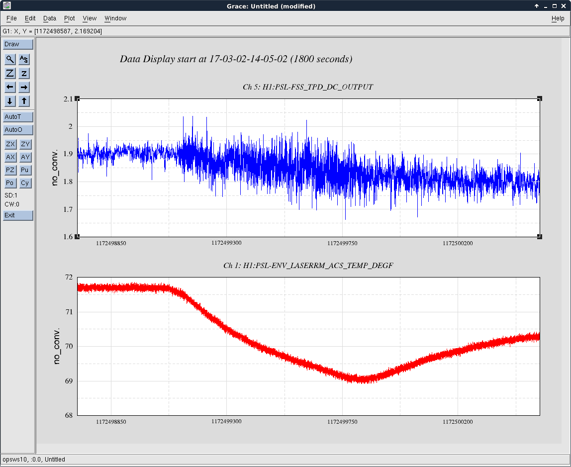
Here's a couple of trends around the relevant time. The first attachment shows all 4 PSL Enclosure laser room temperature sensors. The channels labeled *_ACS_* and *_ACN_* are the sensors at the output of the enclosure AC units, which are turned off during normal operation; the channels labeled *_TBLN_* and *_TBLS_* are the sensors attached to either end of the PSL table. The second attachment shows the south AC sensor (*_ACS_*) and the TPD signal from the FSS RefCav; I used the RefCav TPD as this has shown to be one of the more temperature sensitive alignment in the enclosure. As can be seen, as soon as the temperature begins to dip, the TPD signal becomes more jagged and begins to drop. This is consistent with a real change in temperature in the PSL enclosure. We are currently mystified by this behavior, as the AC units were both off during this time.
Similar behavior was reported by Travis yesterday, and again both AC units were off during the temperature dip. At this time we have no explanation for this behavior. Investigations continue and will update as we know more.
There is a fan in the LVEA return air plenum which continually pushes air into the PSL enclosure even when the AC units are off. This fan is behind the east wall next to the PSL. It would be worthwhile to find out what the temperatures are doing in that space. This return air space is much larger than the supply ducting to the LVEA and therefore the flow velocities are low and there may be air currents driven by convection. Also, winds will have the effect of pressurizing one side of our building with respect to the other side - this may also drive air currents in the return air plenum. Is there a correlation with wind conditions?
I do not know of any temperature sensors in the plenum.
It looks like something was changed on March 1st at about 20:00 UTC. PSL-ENV temp trends show a marked difference in behavior since then, see attached trends. It would be good to figure out what has happened because the temperature dips correlate with extra motion in the IMC, and we have lock losses that follow the temperature dips. Maybe not causal, but it looks like something is not nominal.
At 14:06 (06:06 PT) Richard shut off the main fire pump (in the Carpenters Shop) which had been left on after Tuesday maintenance. The 40 to 200 Hz Breathing Noise appears to have settled down and the range has moved up to 64.2 Mpc.
The impact of this pump in the 3-30 Hz blrms in the LVEA is very dramatic and coincident with the range degradation and recovery.
Are there any other pumps we can turn off to gain some more megaparsecs? :)
Clarification;
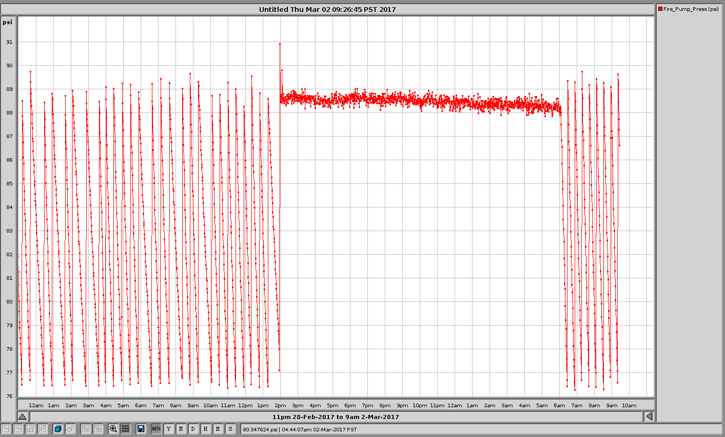
There are two different pump types on the fire protection system. A small pump (1/2 horse power?) maintains the system pressure between 75 and 90 psi. If a fire hydrant or sprinkler system is opened, this small pump cannot maintain the pressure. At this point, pressure switches will bring on one or both of the 50 horsepower pumps (2). These large fire pumps have no remote or automated mechanism to shut them down once running. There are relief valves which spill water on the ground to prevent the pumps from overheating. It looks like we pumped about 700 gallons onto the ground last night.
Most likely the fire department was on site testing the LSB sprinkler system and caused the large pumps to start up. Normally someone in the OSB notices this extra noise and the pumps are then shut off. Richard manually shut the pump(s) off at 6 am Mar 2.
The pressure plot shows the pump running from 2pm Mar 1(Wednesday) to 6am Mar 2 local time.
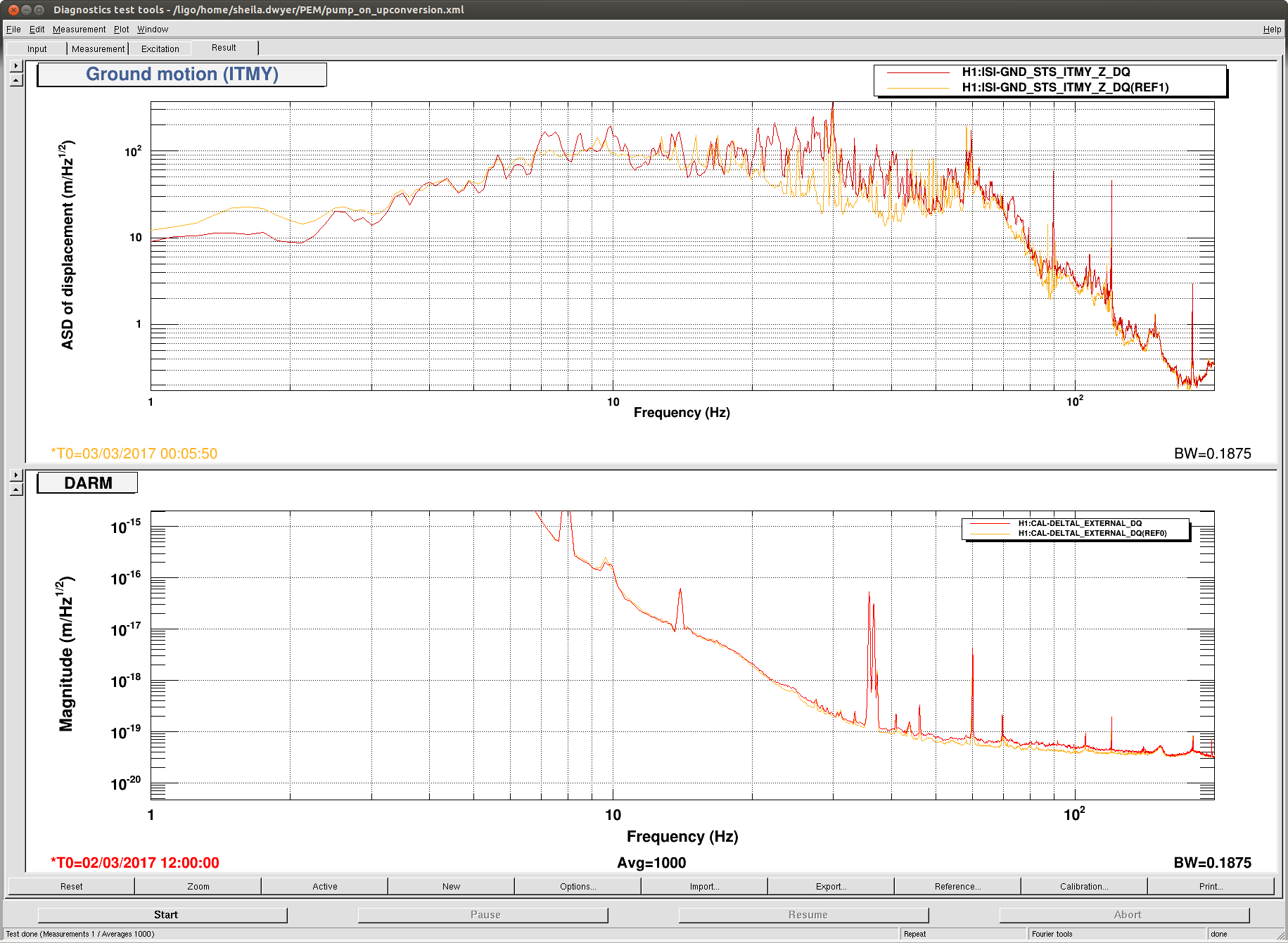
Heather, Sheila
Here is a comparison of the spectra of DARM and the ITMY seismometer with the pump on and off. There is no coherence between the ground and DARM.
   Smooth first half the shift in Observing. Range is 54.9 Mpc, as the "Breathing Noise" continues. The A2L Yaw is quite elevated; Pitch is very low. Other then the EQ ringing down, environmental conditions remain favorable.

   LLO is down due to the SamSat, Turkey earthquake. I would normally run A2L script. TJ reported a problem with the script the other day. I do not know if the script has been fixed, therefore will defer this to the day shift when support is available.
Mag 5.6 Earthquake Samsat, Turkey
TITLE: 03/02 Eve Shift: 00:00-08:00 UTC (16:00-00:00 PST), all times posted in UTC
STATE of H1: Lock Acquisition
INCOMING OPERATOR: Jeff
SHIFT SUMMARY: We've been having some trouble with the PSL and also with some noise around 30-200Hz. Not sure where the noise is coming from. We just got to low noise and are now Observing.
LOG:
PSL head flow error 1-4 again. I have Jason on the phone.
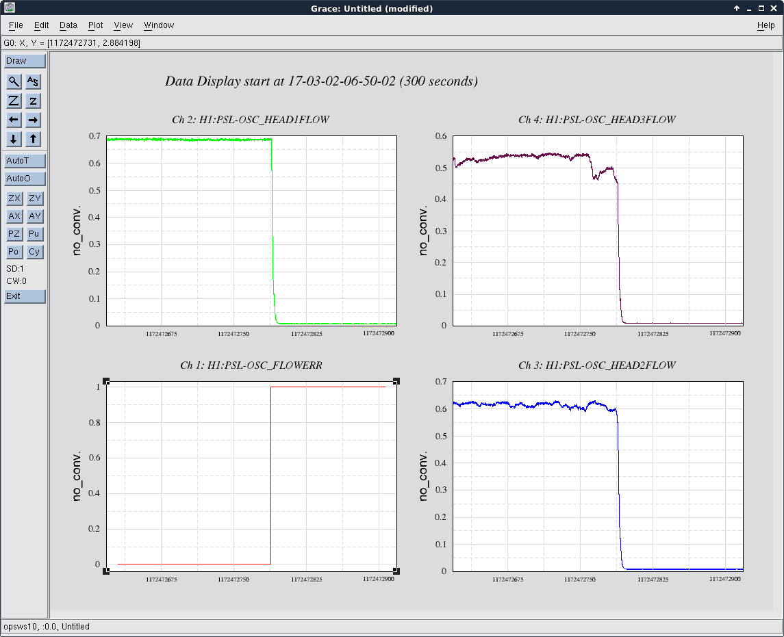
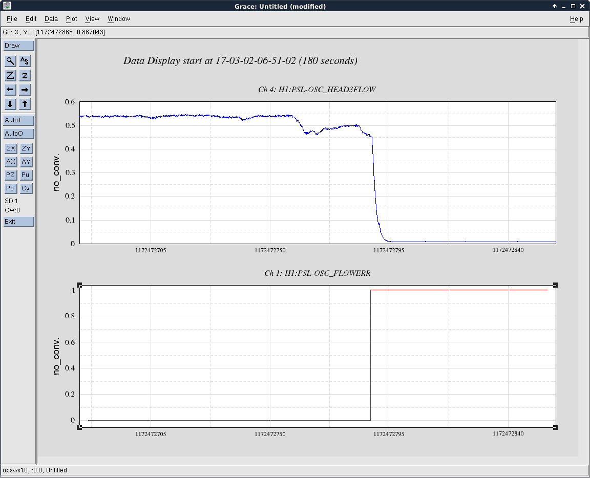
Unfortunately, it didn't sort itself out as we had hoped. Head 3 was the cause of this trip, which was not surprising given the behavior we witnessed after restarting the laser after the night's previous trip. The first attachment shows the 3 active laser head flow sensors and the relevant interlock signal. The second attachment shows a slightly zoomed view of the signal from the laser head 3 flow sensor. Nothing else looked suspect.
The system restarted without issue. Given the behavior seen after the first trip, we observed the flow rates for several minutes before calling everything good to go; no issue was seen during this time. Given the increase in frequency of this interlock tripping, I think we are witnessing 2 flow sensors on their last legs.
FRS 7539 filed for this trip.
I ran an initial alignment because it kept losing lock before DRMI locking and I was hoping maybe it would help the 30-200Hz noise from before. It didn't. Range is still in the mid 50'sMpc and the breathing noise continues.
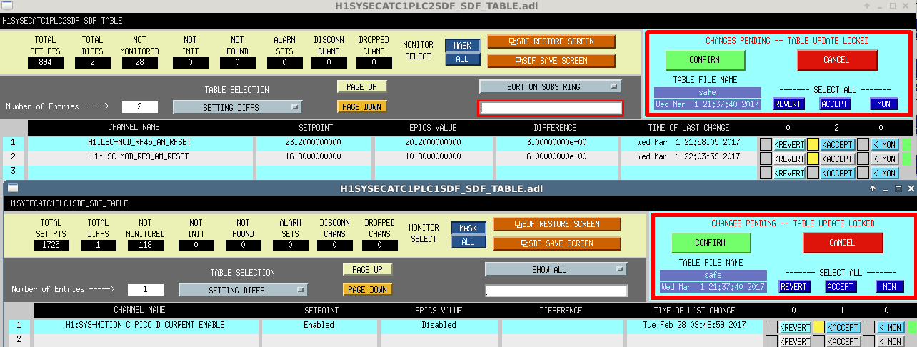
I had to accept some SDF diffs that I'm a bit confused by, but everything seems to be running fine.
PSL tripped with a head 1-4 flow error. I am on the phone with Jason getting things running again.
Laser restarted without issue (at first, more on that below). TJ had to reset the noise eater, and after that all the PSL subsystems came back without issue.
Once everything was recovered TJ noticed the Head 1-4 Flow warning light blinking. Sure enough, on the Chiller Beckhoff screen the flow through the laser heads was flashing; there is a range above the trip point that the system alarms before tripping. We observed this for several minutes, and noticed that the flow reading for head 3 was fluctuating between 0.5 and 0.6 lpm, causing the warning alarm to flash. Unfortunately there is not much that can be done about this remotely. TJ is going to continue locking the IFO and we hope this will sort itself out.
I filed FRS 7537 for this trip.
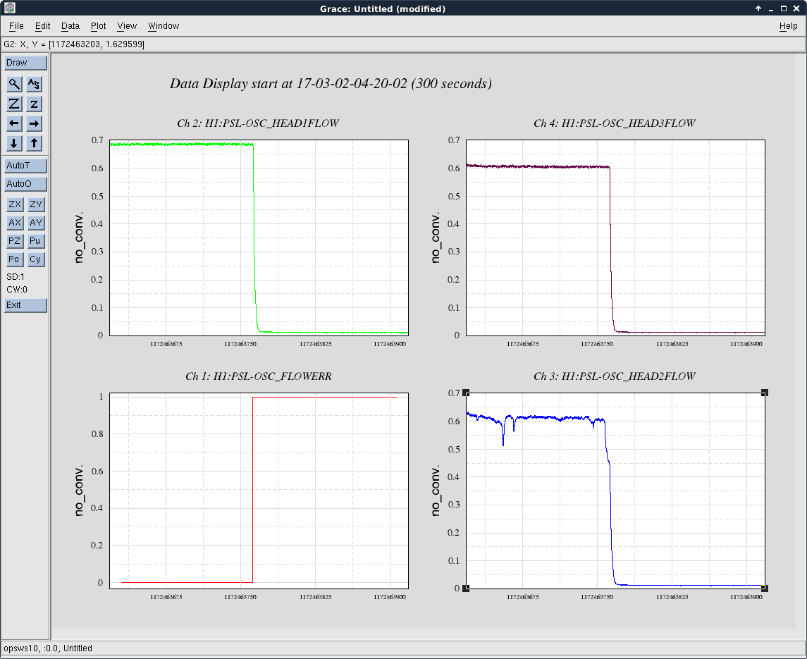
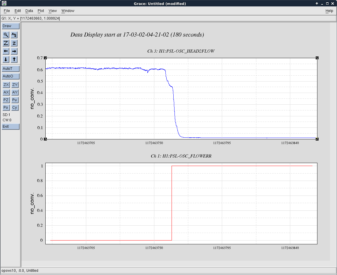
Some further forensics. Head 2 was the culprit this time, dropping below the trip point and therefore tripping the "Head 1-4 Flow" interlock. The first attachment shows the 3 active laser head flow sensors and the "Head 1-4 Flow" interlock. The second attachment is a slightly zoomed in view of the Head 3 flow sensor signal. Nothing else with the system looks suspect.
Edit: Uploaded the wrong image files; this has been corrected.
JimW HughR
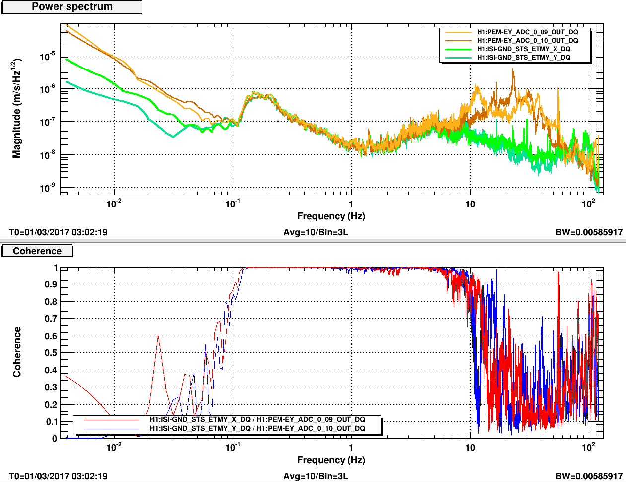
The first attachment is from late afternoon yesterday, before the winds started picking up. There is still a large difference between it and the ISI GND STS below 100mHz. This may be thermal equilibrating or maybe the masses need centering again. I'll look at this today; must be done at EndY.
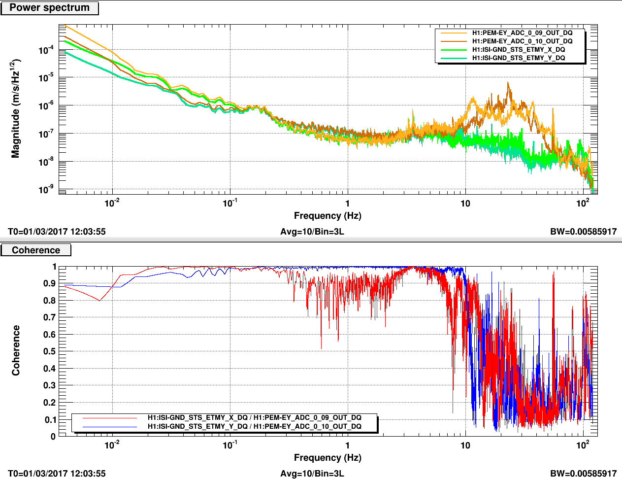
The second attachment is from early this morning with sustained 20mph winds; pretty steady direction from the SW to SSW. The coherence and spectra look much better with the greater input.
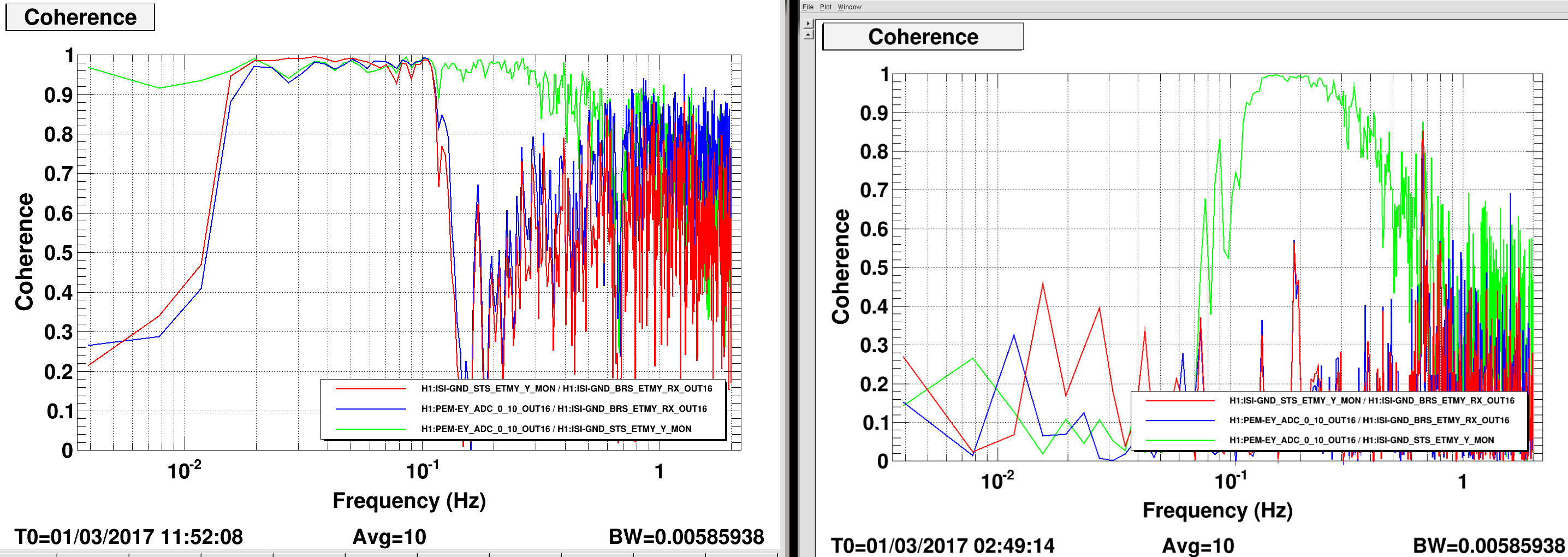
The third attachment looks at coherence to the BRS Tilt. The coherence to the right is when the wind is low and to the left shows when the wind is high. Bottom line: not much difference between the colocated sensor and the GND seismo on the floor.
At the end of the commisioning break today, I went down to EY and recentered the masses on the T240. This sensor doesn't have the full integration into the data system, so it's not just a button push. Richards DB9 connector makes this pretty easy though. Pin 5 is the analog ground, so UVW are read by read getting the voltages from pins 1-3 to 5. To re-center, you need a 5V supply (Richard loaned me one), connect pin 7 to the supply ground and put the +5v on pin 6 for a(n actual) second. When I got to EY the masses were at 1-2v, after centering they were between .08-.2v.
I looked at 2-k seconds of data from Wednesday night at 6:00 UTC. Plots are attached. The ASD is in rad/rt(Hz). Once again, the T240 seismometer on the platform sees a substantially larger low-frequency signal compared to the BRS or the ground STS. This instrument performed much better when it was on the ground.
This suggests that it is picking up extra signal when it is on the platform, which is not real tilt (as the BRS signal is much smaller). It is unlikely to be temperature since Hugh's additional foam insulation made no difference. It could be temperature noise on the table feet so it may be a good idea to wrap the feet also in the same foam insulation and see if that makes any difference.
Another possibility is that the low-frequency excess could be some form of (parametric) down-conversion from the excess high frequency motion of the platform (10-50 Hz). We have seen such noise on the BRS flexures, so it would not surprise me if similar noise exists in seismometers. I'm more surprised that the platform is shaking so much at high frequencies. I think this calls for a better design of the platform feet.
