chandra.romel@LIGO.ORG - posted 14:36, Tuesday 16 May 2017 - last comment - 16:18, Tuesday 16 May 2017(36213)
Troubleshooting x-beam manifold pressure discrepancy
[John, Chandra]
More investigation on leak hunt of x-beam manifold. Here's what we're trying now:
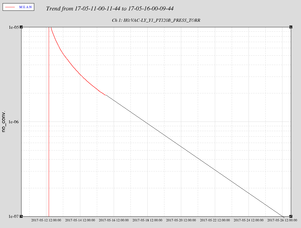
- Valved out IP5 & IP6 on x & y beam manifolds to measure rate of pressure rise (looks like x is rising 2-3x more than y)
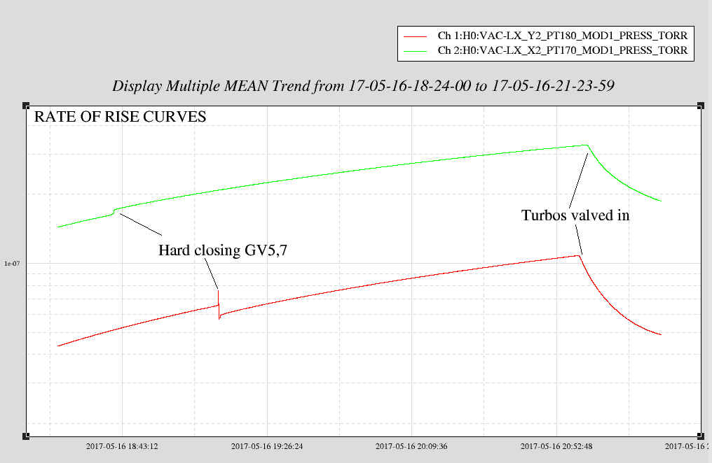
- Hard closed GV5 & GV7 to confirm no help from adjacent cryopump (no change in rate of rise)
- We found that hard closing GV5 does not change status on MEDM from yellow to red (FRS 8142)
- GV7 hard closed fast at around 20 psi
- GV5 wouldn't hard close at maxed out 80 psi, so we partially re-opened to re-seat the gate. Then it hard closed around 40 psi with a very loud bang
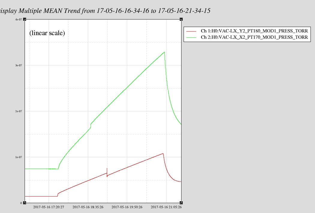
- Valved in x & y beam manifold turbos to trend the pressure drop. Inlet pressures (foreline pressures) before and after valving in:
- Y: valve closed: 5.2e-8 Torr (7.6e-3 Torr); valve open: 9.0e-8 Torr (7.6e-3 Torr)
- X: valve closed: 2.2e-9 Torr (1.0e-3 Torr); valve open: 5.2e-8 Torr (1.0e-3 Torr)
- Note: X turbo is being backed by leak checker equipped with a turbo; Y turbo is backed by scroll only
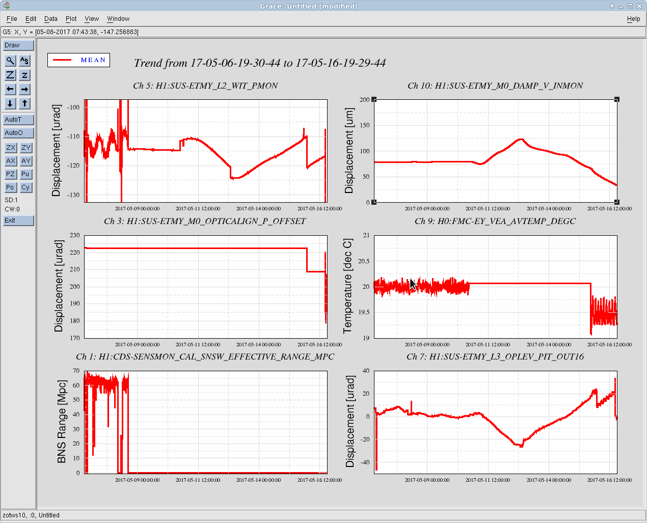
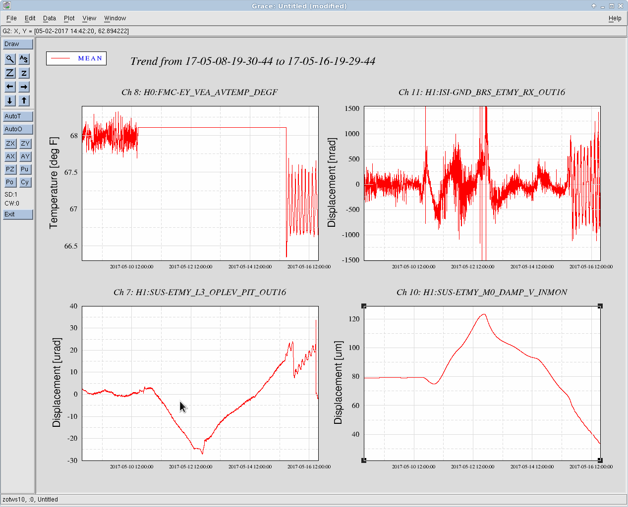
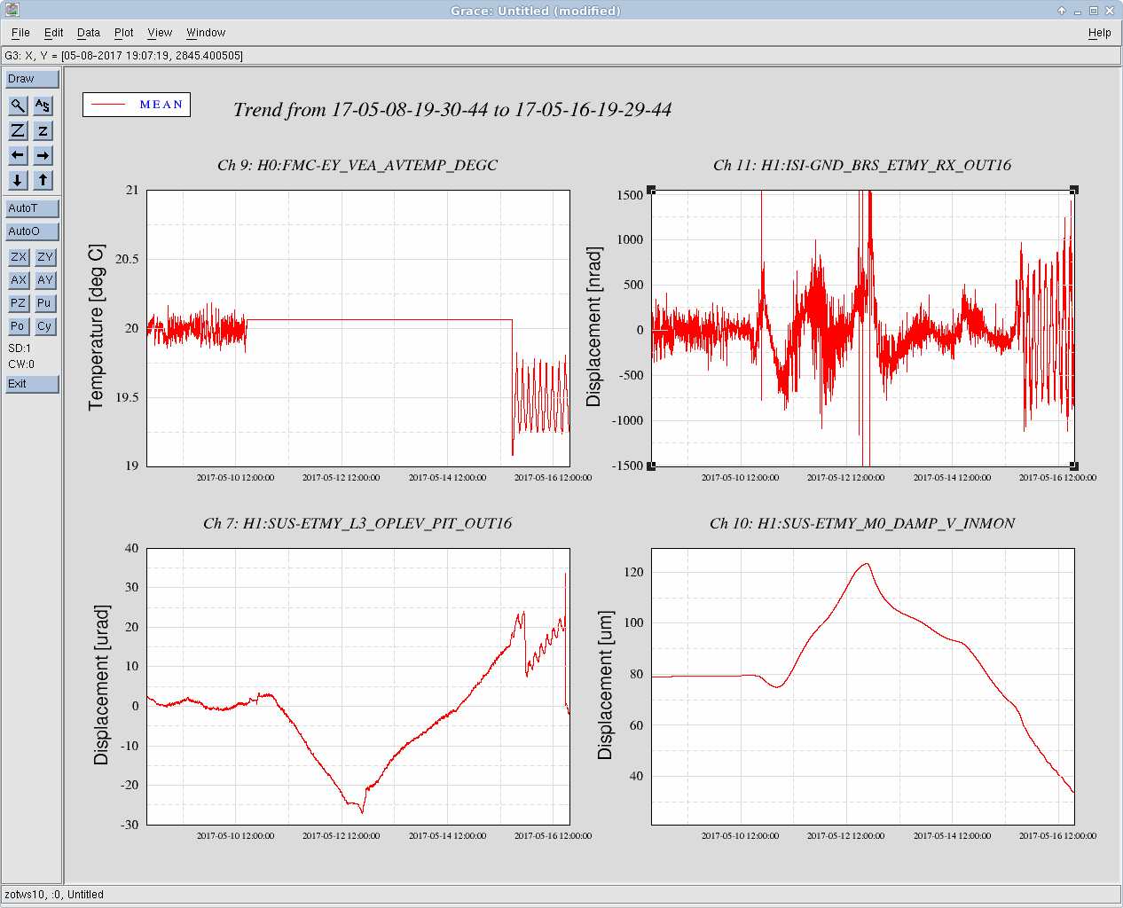
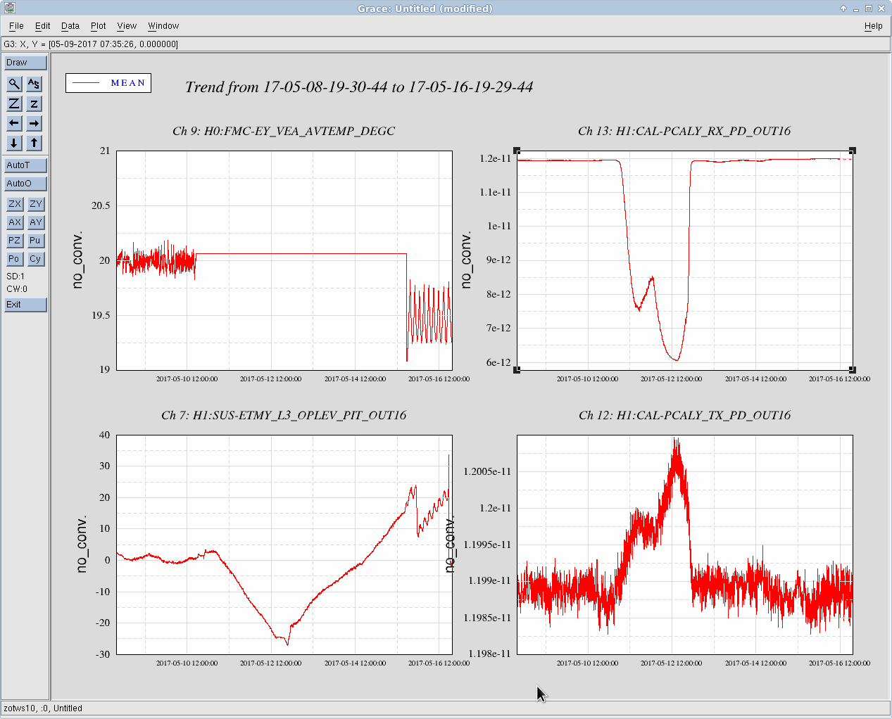
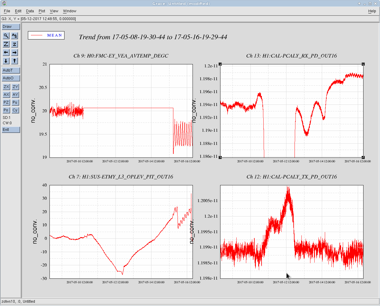
- Attached is trend so far (log scale & linear scale)
- NOTE that PT-180 was baked by Kyle many months ago when we were investigating why these two new hot cathode ion gauges drift up in pressure while the cold cathode (PT-120) doesn't follow same trend. Do we trust the gauges??
- Chris will refill the three empty He gas bottles so we can resume spraying the tube tomorrow
Images attached to this report
Comments related to this report
In regard to GV5 not showing as hard closed on the medm screen.

I looked at the Beckhoff code. It appears that I am just not seeing a change in signal (from 0 to 1) for the closed limit switch. Both the code and documentation agree that this should be LY terminal 2 channel 4.

On April 8 2015 Kyle reported that GV5 hard closed (https://alog.ligo-wa.caltech.edu/aLOG/index.php?callRep=17748). I see this in the minute trends (attached). This is the most recent time I can find GV5 being hard closed from the alogs.

On April 26 2016 LY was upgraded to Beckhoff (https://alog.ligo-wa.caltech.edu/aLOG/index.php?callRep=26803).

I guess we should check the wiring into the Beckhoff chassis?
Non-image files attached to this comment

From minute trends, the last time that GV5 hard closed is on March 14 2016.

https://alog.ligo-wa.caltech.edu/aLOG/index.php?callRep=26065
Non-image files attached to this comment