john.worden@LIGO.ORG - posted 06:16, Saturday 13 May 2017 (36172)
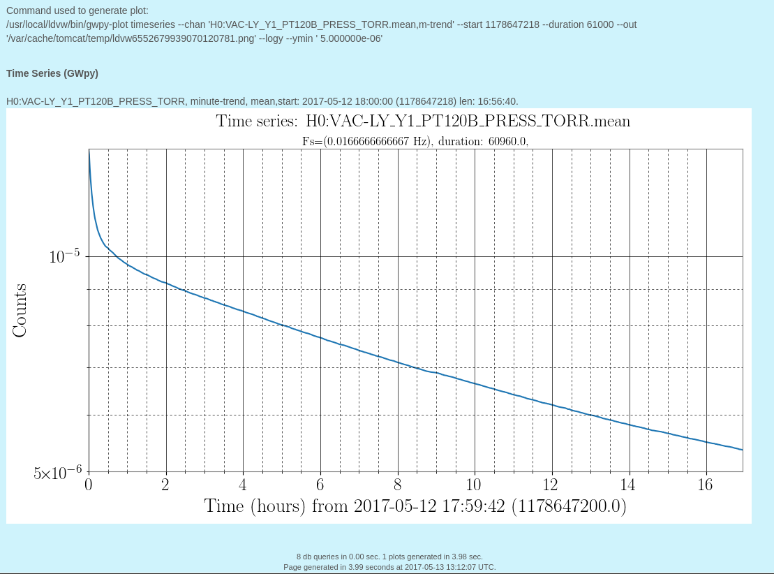
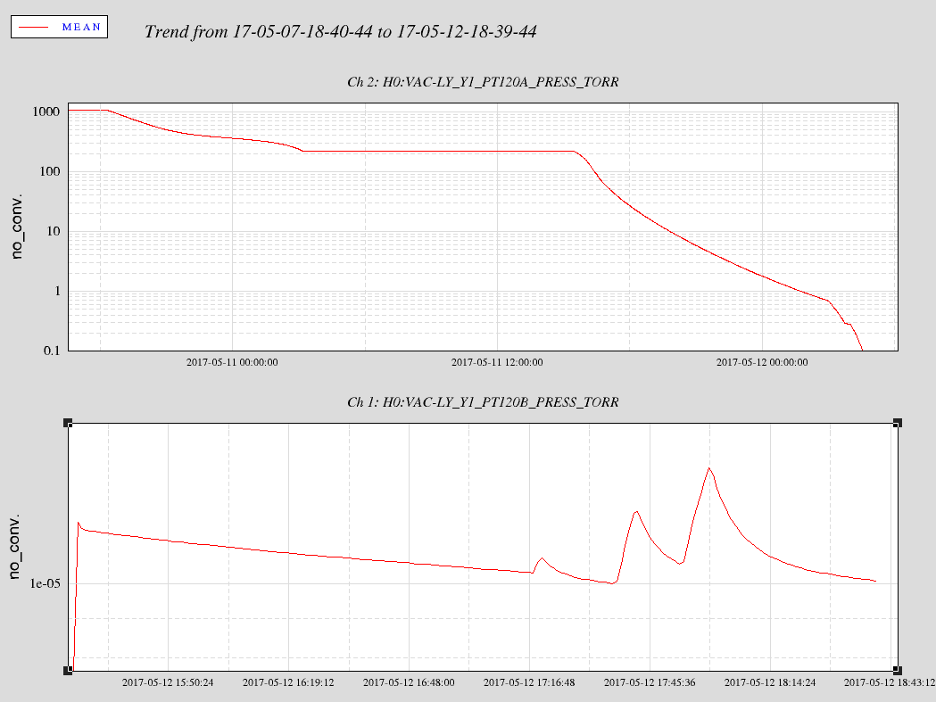
Vertex pumpdown progress
PT120B looking normal.
Images attached to this report
PT120B looking normal.
TITLE: 05/12 Day Shift: 15:00-23:00 UTC (08:00-16:00 PST), all times posted in UTC
STATE of H1: Planned Engineering
INCOMING OPERATOR: None
SHIFT SUMMARY:

Pump down of vertex continues.
Aidan, Nutsinee and TJ working on HWS table. Removed panel to enlarge beam apertures.
Robert and Pep working at end Y. Lost connection to weather stations and dust monitors as part of their work.
Apollo working on FMCS upgrade at end Y.
Betsy running transfer functions on ITMX.
LVEA is laser hazard.

LOG:

15:21 UTC Betsy running transfer functions on ITMX
15:50 UTC Betsy, Calum and Nicole to mid Y then mid X
15:57 UTC TJ transitioning LVEA to laser HAZARD
16:05 UTC TJ done
16:07 UTC TJ and Aidan to HWS table
16:11 UTC Christina to mid X
16:18 UTC Gerardo taking viewport equipment to LVEA
16:25 UTC Nutsinee to HWS table
17:03 UTC Aidan, TJ and Nutsinee back. Brought HWS table panel out to have Bubba enlarge the beam apertures.
17:43 UTC Richard to LVEA to check functioning of Beckhoff laser safety interlock on table
17:47 UTC Richard back
18:25 UTC Jeff B. opening rollup door between cleaning area and receiving
18:30 UTC TJ to squeezer bay
18:37 UTC TJ back
18:38 UTC Jeff B. done
19:23 UTC Pep and Robert working at end Y, turned wifi on
20:11 UTC Chandra to LVEA to check on annulus
20:20 UTC Jeff B. to cleaning area
21:12 UTC Bubba to LVEA to turn off cleanrooms
21:23 UTC Jeff B. done
21:30 UTC TJ to cleaning area
21:36 UTC Mike and guest to LVEA
21:37 UTC Nutsinee working with TJ in cleaning area
21:42 UTC Aidan to cleaning area to work with TJ and Nutsinee
22:03 UTC Mike and guest out of LVEA
22:04 UTC Robert and Pep to end Y
22:51 UTC Robert and Pep back
22:57 UTC Nutsinee back
Peter F. and Kiwamu,
Related logs: 36106 and its comments
We looked into several (randomly chosen) lock loss examples to study how much the spot position can typically move on the test masses immediately after lockloss.
Summary:
Locklosses:
We randomly picked the following lock losses:
Apr 04 2017 13:02:26 UTC (Pin = 30 W)
May 05 2017 23:48:06 UTC (Pin = 30 W)
Dec 08 2016 06:09:25 UTC (Pin = 30 W)
Nov 12 2015 18:11:16 UTC (Pin = 22 W)
Jul 27 2016 08:15:22 UTC (Pin = 50 W)
See the attached pdf for the actual oplev signals and arm power signals for those times.
Angle motion to spot position:
Because of the negative g-factor design in aLIGO, the effective lever arm for the light in the arms is amplified by 1/(1 - gi * ge) = 5.8 for the spot positions where gi and ge are the g-factors for ITM and ETM, respectively. Therefore the lever arm is L/(1-gi*ge) = 23.5 km. In order to bring a beam with 5 cm radius to the edge of a test mass (with 34 cm diameter), the beam spot must move by 340 mm /2 - 50 mm = 120 mm. To produce such a large excursion in the spot position on an optic, one of or both test masses needs to tilt roughly by 120 mm / 23.5 km = 5 urad.
Some observations:
Usually ETMY PIT experiences the fastest change in the first 1 second after lockloss. It can easily reach 5 urad within 1 sec. Other pitch signals also showed a similar behavior in that they move relatively fast and typically reach 3-4 urad within 1 sec. All the pitch motions tend to go negative for some reason.
In contrast, the yaw motions didn't move as much as pitch motions. They typically jump by less than 1 urad at the beginning and later drift by a few urad relatively slowly.
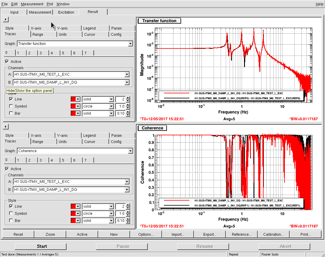
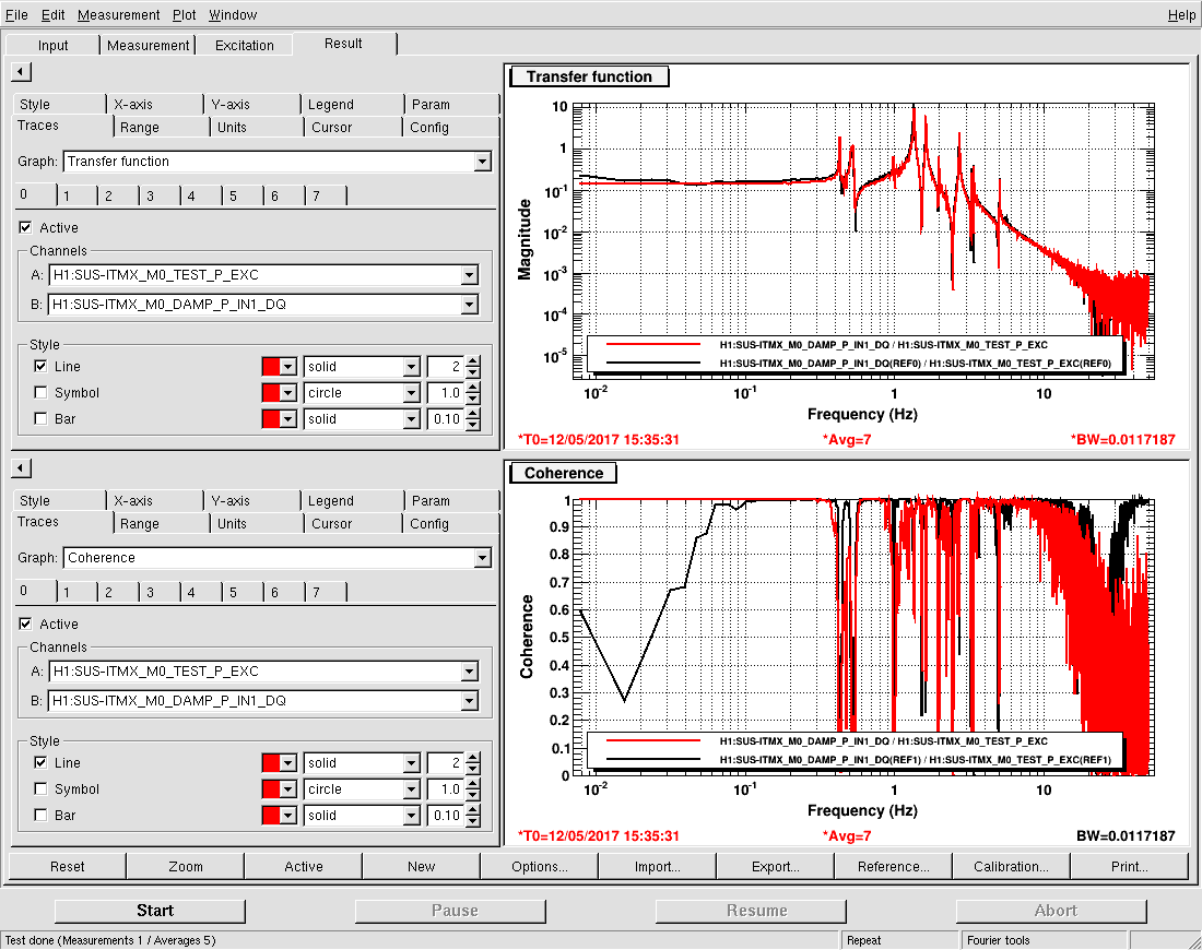
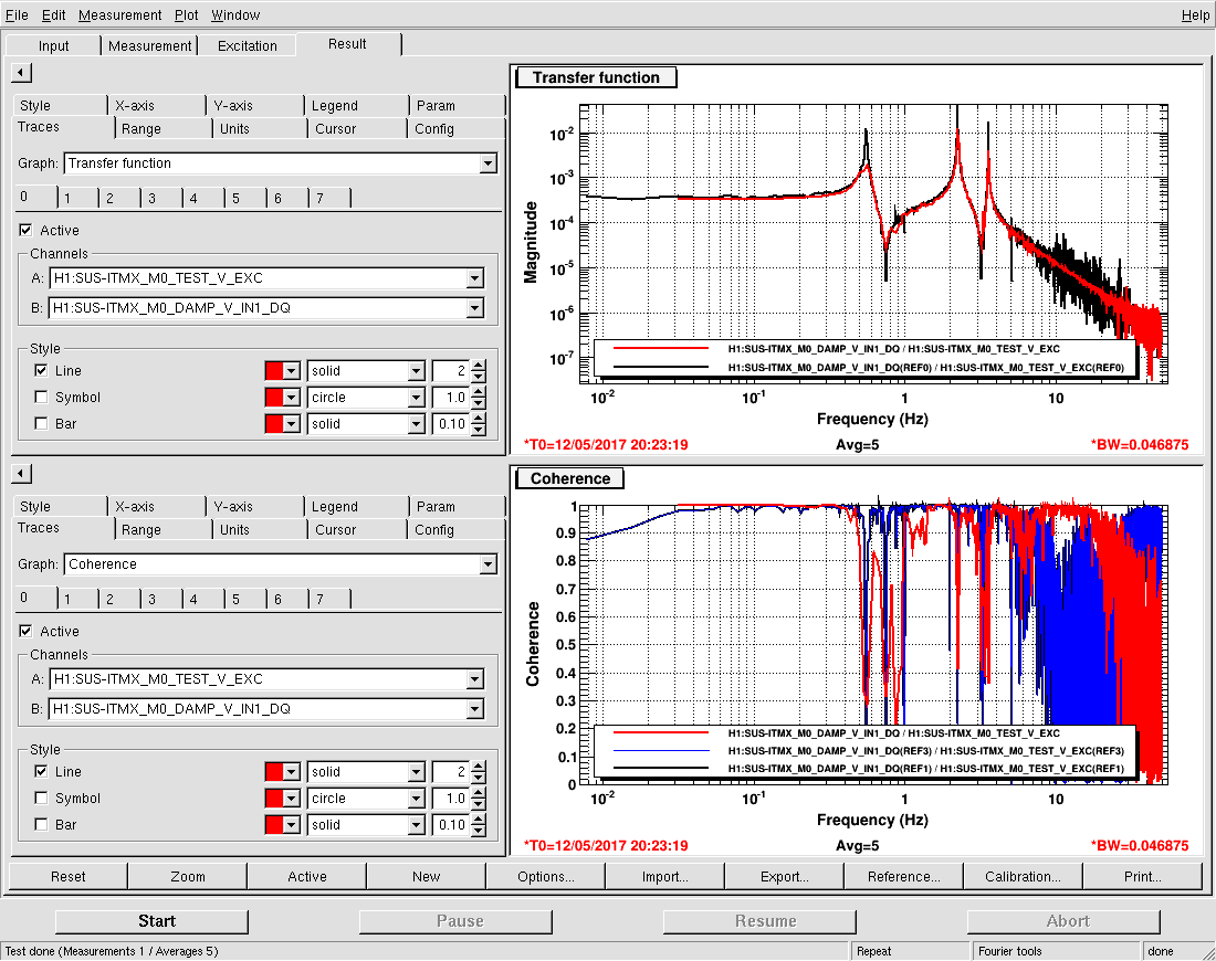
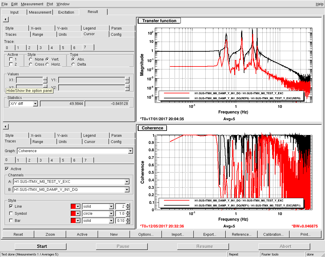
Although we are still pumping down the corner vertex volume, TFs of the ITMX suspension show good signs of healthiness (no rubbing). I think Gerardo mentioned being in the e-6 Torr range. I cannot get the matlab auto TF script to work (with absolutely no time to troubleshoot this week) so I've just taken regular DTT looks with templates. V, P, L all look good, Y main peaks are all in a good place - but not sure why the offset in the overall DC level - we've seen this before, again, no time to hunt and troubleshoot. Haven't finished all of them.
- Robert and Pep working at end Y
- Aidan, TJ and Nutsinee working on HWS table
- Pumpdown of vertex continues
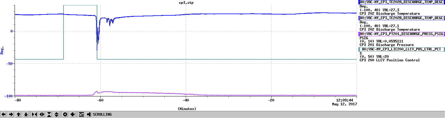
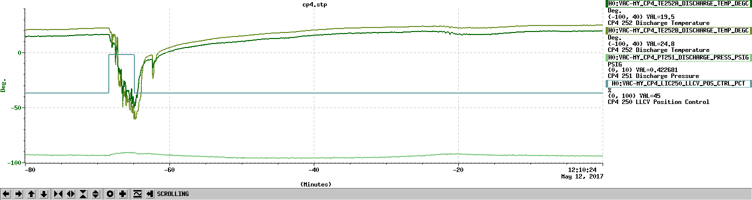
Starting CP3 fill. LLCV enabled. LLCV set to manual control. LLCV set to 50% open. Fill completed in 473 seconds. TC B did not register fill. LLCV set back to 20.0% open.
Starting CP4 fill. LLCV enabled. LLCV set to manual control. LLCV set to 70% open. Fill completed in 208 seconds. TC A did not register fill. LLCV set back to 45.0% open.
Raised CP3 to 21% open.
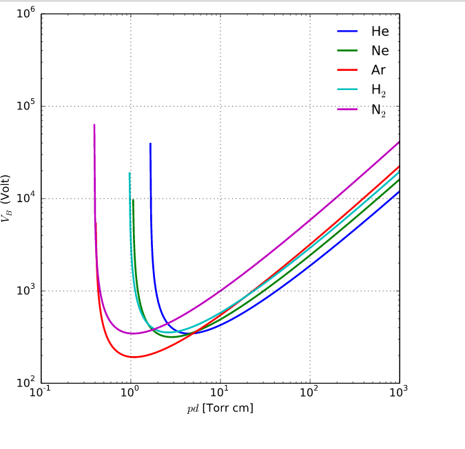
WARNING: don't turn on high voltage until pressure reads e-6 Torr range on PT-120B gauge
A reminder - Paschen's curve of breakdown voltage vs pressure. And note that we have gaps at feedthroughs in the mm range rather than cm.
From Wikipedia;
https://en.wikipedia.org/wiki/Paschen%27s_law
GV4 annulus vacuum is surviving on the IP alone at 5 mA. I left the turbo hardware connected, but everything is powered OFF.
Valved out water from QDP80 pump and turned booster pump off. Left x-beam manifold turbo station energized until I leave site.
Vertex turbo inlet pressure is 2.1e-6 Torr. BSC2 pressure is 7.9e-6 Torr.
| Work Permit | Date | Description | alog/status |
| 6637 | 5/12/2017 8:40 | The pirani gauge is not functioning properly and not allowing the Cold Cathode to turn on. We will force the Value of COLD_CATHODE_HIGH_LIMIT_TORR to 1 to allow the Cold cathode to turn on. This will be in place until we vent and can replace the guage. | |
| 6636 | 5/11/2017 13:18 | We will wrap GV7 actuator with fun mylar, spray He, and stroke the valve for thorough leak testing. This valve is currently soft closed from vent activities so we will monitor the volume's turbo pump closely and not leave unattended while GV7 is open. | |
| 6635 | 5/11/2017 12:30 | Remove RF Oscillator Source (24MHz) S1000581 for troubleshooting. Error with read back signals. | 36145 |
| 6634 | 5/11/2017 10:43 | Take pictures of the views from each viewport on HAM2. To do this requires the removal of one or more viewport cover at a time and illumination in the chamber to identify and take pictures of IO optics/baffles. All viewport covers will be restored at the end of the project. | |
| 6633 | 5/11/2017 8:55 | Switch to laser hazard in LVEA, in order to operate HWS sleds. | |
| 6632 | 5/10/2017 10:24 | Update MEDM screens to use python scripts pursuant to E1700056 | |
| 6631 | 5/10/2017 9:23 | Verify installed serial numbers of Photo diodes on the tables. LSC, WFS | |
| 6630 | 5/10/2017 8:50 | Decouple purge air from vertex volume, blow down, connect QDP80 roughing pump and start roughing down the vertex volume and leak check HAM4 north door, BSC3 west door and two conflats on HAM3 reducer that were removed. Verify high voltage supplies are off. | |
| 6629 | 5/10/2017 8:15 | Rebuild HWSY in-air table. Realign HWSX and HWSY to ITMs through SRC. Diagnostics on HWS systems with CO2 laser and RH. 36-hour RH tests. | |
| 6628 | 5/10/2017 7:42 | Reroute and untangle cables and plumbing under the PSL table in the enclosure. This will require the laser be down. | |
| 6627 | 5/9/2017 10:30 | connect leak checker to x-beam manifold and valve in main turbo pump. will valve out IP before spraying He. | |
| 6626 | 5/8/2017 16:46 | Crane over leak checker and He gas bottle in preparation for leak checking components on X-beam manifold. We may have detected a vacuum leak due to PT170 pressure rising (vs. PT180 on Y-beam manifold falling) after isolating volumes. Will connect the leak checker to X-beam manifold main turbo. | |
| 6625 | 5/8/2017 10:55 | Replace the ESD HV power supplies (±430V) for ITMX, ITMY and ETMX. Supplies for ETMY have already been replaced. See alog 3218. | 36143 |
| 6624 | 5/8/2017 8:32 | Disconnect cabling for the Hartmann table. Table will be moved to allow access to WHAM4 north door. Part of E1700124 vent procedure. | 36144 |
| 6623 | 5/8/2017 7:27 | Install new HVAC/Building controls at both end stations. | |
| 6622 | 5/8/2017 7:15 | Install Air Trap/Bleed (ECR #E1700096) in PSL Crystal Chiller return line. Will need the PSL to be down during the installation. | |
| 6621 | 5/8/2017 7:11 | Install filter supports in the PSL enclosure. This will mount the in-line canister filters vertically. | 36116 |
| 6620 | 5/5/2017 14:34 | Check HEPI Fluid System Accumulator Pressures: All ISIs & HEPIs Offline, spin done HEPI Pumps, check and charge Accums AR, reverse shutdown. Can do buildings separately. | |
| 6619 | 5/5/2017 14:29 | 1) Turn Kobelco on first thing Monday morning to warm it up for dry purge air. 2) Record vertex RGA scan. 3) Hard close GV 1,2 and soft close GV 5,7. 4) Isolate main ion pumps #1,2,3,4. 5) Verify turbo is isolated. 6) Isolate RGA. 7) Turn off cold cathode gauges. 8) Turn off HV supplies. 9) vent vertex (several hours). 10) Vent annulus volume on BSC3 door and HAM4 door. Doors will be removed Tuesday morning. | |
| 6618 | 5/5/2017 13:39 | Pursuant to ECR E1700123, I will remove the lasers for the HAM optical levers during the upcoming vent; there are currently 3 lasers in total (no laser in HAM3 oplev). It has been decided that these lasers are destined for 3IFO, so they will be placed into 3IFO storage with the rest of the 3IFO oplev equipment at Mid-X. No viewports will be exposed during this work. | |
| 6617 | 5/5/2017 13:26 | Add the Beckhoff MSR temperature channels to the cell phone alarm system, alarm if temps exceed 30C (86F). | |
| 6616 | 5/4/2017 13:23 | The ITMy oplev laser is showing signs of a failing laser diode (LHO alog 36024). As a preemptive emergency corrective maintenance while LLO is down I will swap this laser for a new one recently stabilized in the Pcal lab. No viewports will be exposed during this work. | |
| 6615 | 5/4/2017 10:28 | I would like to take some measurements with the end stations HWS. Before the power up, ALS beams need to be unshuttered with PZT2 YAW misaligned. Leave the shutters opened until a few minutes into full power. Then return to nominal configuration. | |
| 6614 | 5/1/2017 14:00 | Install a bug fix release of the 0.14.1 nds2-client software. I will also make this the default nds2-client on the workstations. This only applies to the debian 8 workstations in the control room. This is to fix a issue if a user was to use ligodv (the matlab precursor to ldvw). | |
| 6613 | 5/1/2017 12:54 | Give brief tour of LVEA/end station VEA to Fellows | |
| 6612 | 5/1/2017 11:44 | Reboot h1dc0 before its uptime exceeds 208 days (15th May 2017). | |
| 6611 | 5/1/2017 11:43 | reboot all front end computers with more than 208 days uptime (22 machines) plus h1nds0. | |
| 6610 | 5/1/2017 7:36 | Lubricate all Axivane supply fans on site. This is a quarterly lubrication. | |
| 6609 | 4/28/2017 13:51 | Soft close GV 5,7 to move cleanroom in biergarten |
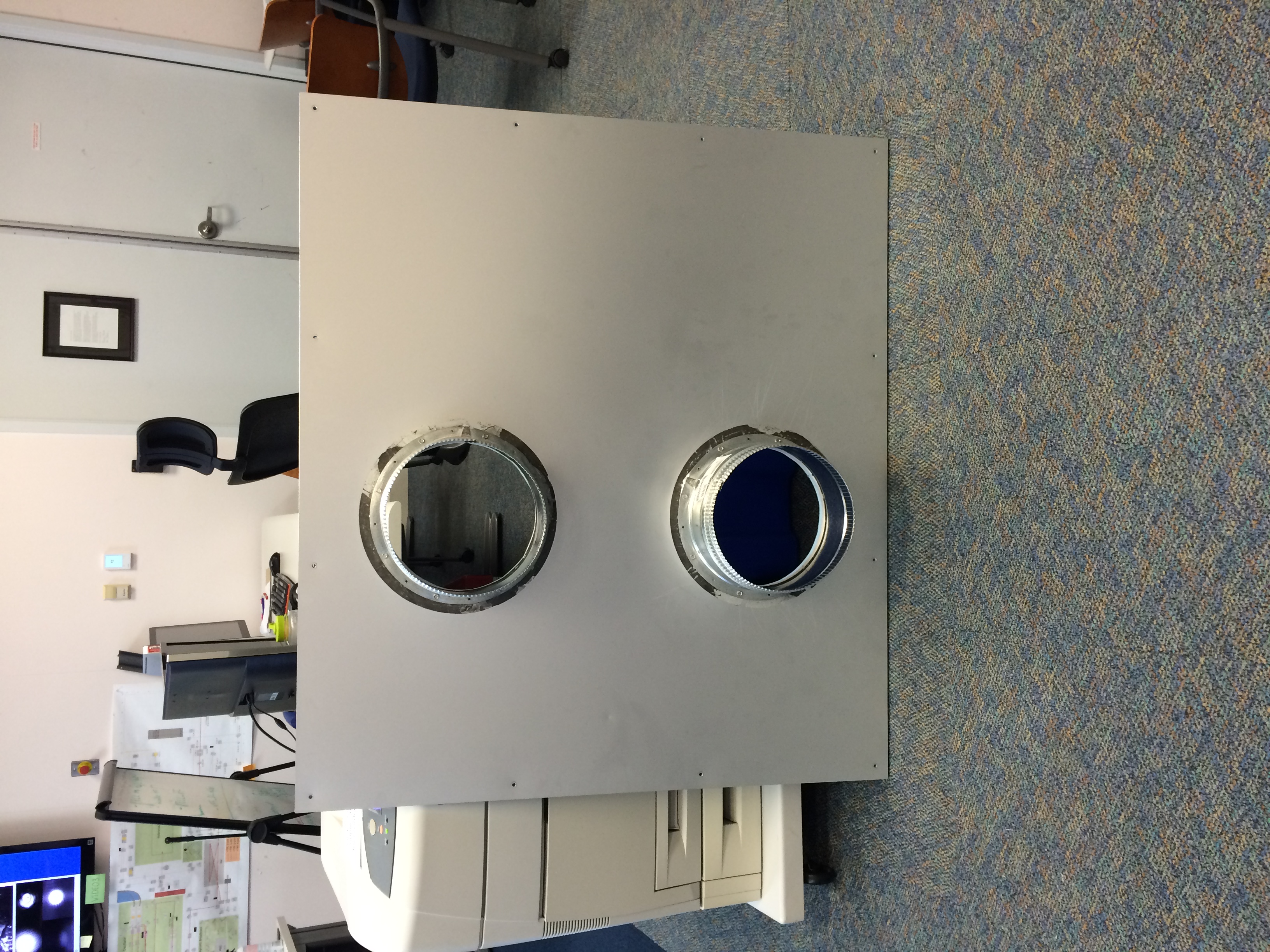
We noticed the other day that the HWS table beam apertures don't line up very well with the persiscope optics. After we got the viewport covers off today, I could see that the periscopes are lined up with the in-vacuum lenses. The actual problem is that the table is about 2" to the left of the design position because of an interference with the electronics rack.
We decided the simplest solution is to just widen the apertures. So we've removed the panel and Bubba has it in the carpentry shop right now. We're going to widen the holes to match the inner diameter of the beam tube adapters.
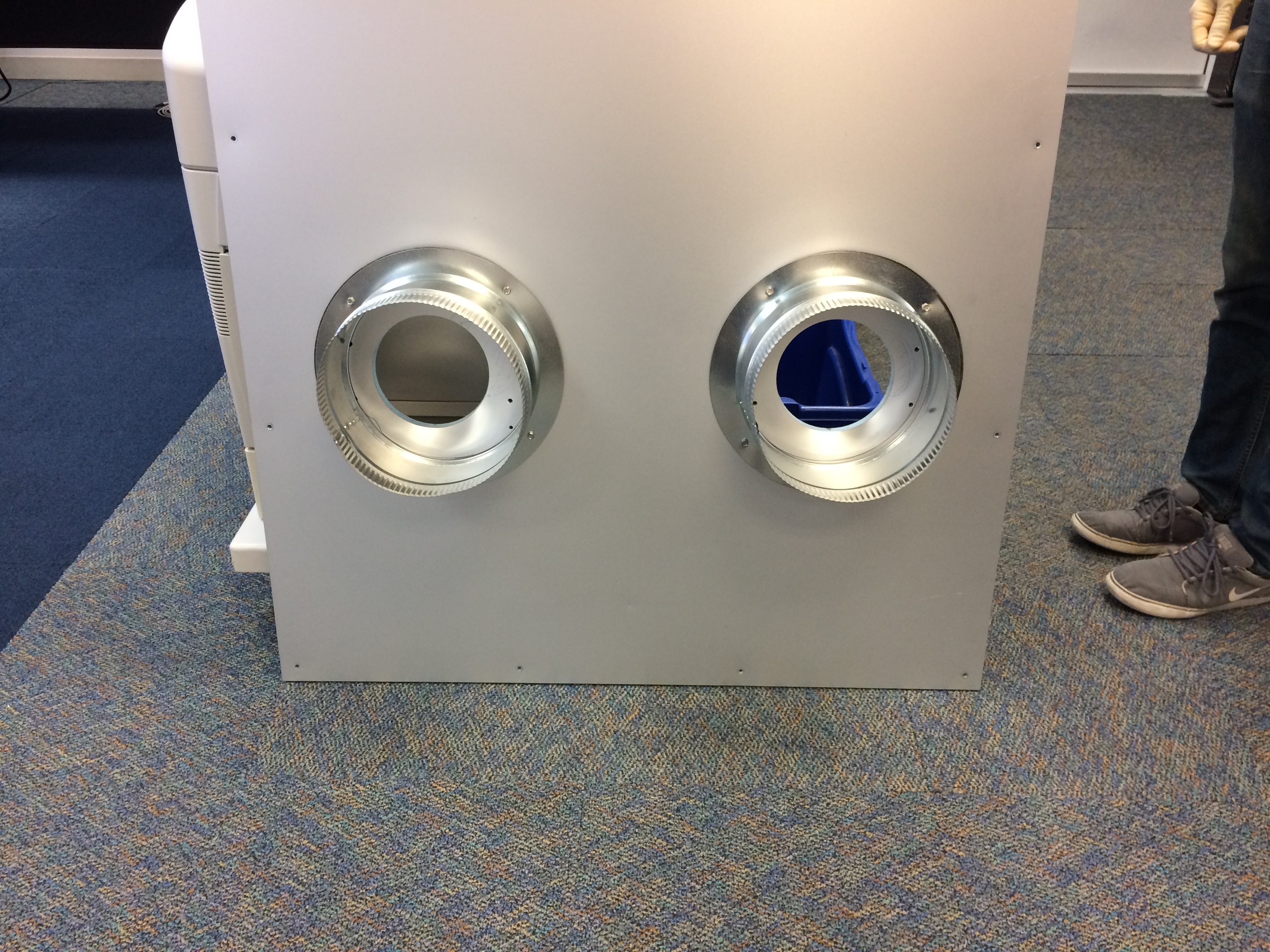
The modified panel is shown here:
I have reconnected the cold deck duct in the MSR room to help with the cooling until I can figure out what is wrong with the #3 Mitsubishi that serves that room.
The temperature should start going down in that room, Carlos and I are monitoring this closely.
Modified Software interlock to allow the Cold Cathode gauge to be turned on due to problems with pirani gauge. This is the older style of two gauges A being the pirani and b being the cold cathode. Patrick forced the Value of COLD_CATHODE_HIGH_LIMIT_TORR to 1 on LVEA LY vacuum control computer. This allowed the Cold cathode to turn on. This will be in place until we vent and can replace the guage.
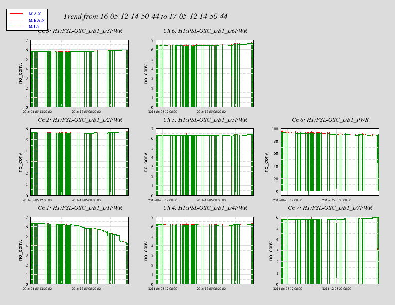
Of the four diode boxes for the high power oscillator, diode box 1 is the one that has exhibited the greatest
degradation in output power.  A look at the individual pump diodes for that box shows that only diode 1 is the
one that shows the largest decay.
Scroll pump can't keep up with load yet, so the QDP80 will remain as the turbo's roughing pump tonight. Pressure set point is 0.65 Torr. Safety valve will close upon pressure breach or pump failure. Cooling fan is blowing on turbo.
Vertex pressure is 0.05 Torr.
Leaving site now.
[Kyle, Chandra]
Leak checked GV7 this evening by bagging GV nipple with mylar and inflating with helium at constant flow for 30 minutes. Oxygen sensor was used to verify air displacement. The leak checker detected a leak that crept up to 3.8 x 10^-9 Torr-L/s after several minutes, but then decreased while the bag was still saturated with He. Then we opened the valve and slowly soft closed again (all while maintaining He flow). During the stroke the He signal in leak detector continued to drop. We may have been detecting He from migration. We depleted an entire (small) bottle.
WP 6635
FRS 8091
This morning the 24MHz RF oscillator source for EY showed a timing error. Chassis was powered cycled and timing error cleared. RF output levels for unit are within spec. Richard did noticed the readback signals for this unit were incorrect. Unit is currently in the EE lab for troubleshooting.
S1000581
The RF Source (24MHz) is now reinstalled at EY. Both the timing and readback signals errors have cleared.
1. Timing error for RF source EY was reported.
2. Unit was power cycled and timing fiber reseated. Unit locked according to front panel led lights.
3. The readback frequency, error, and control signal all displayed incorrect values in MEDM.
4. Looked at RF levels and frequency outputs. All within spec.
5. Unit was brought back to EE lab.
6. The input IC buffer on the timing interface 1 PPS locking board was replaced. We later convinced ourselves IC buffer never had an issue.
7. The FPGA on the timing slave was reprogrammed. We used the same Version 4 subversion 118 code.
8. Unit was reinstalled at EY. Unit locked within 5 minutes and all readback signals now show expected values.
F. Clara, R. McCarthy, M. Pirello
Damping completed and flanges back on. No hitches. Three viton corks are in, preliminary laser vibrometry looks good. More later.
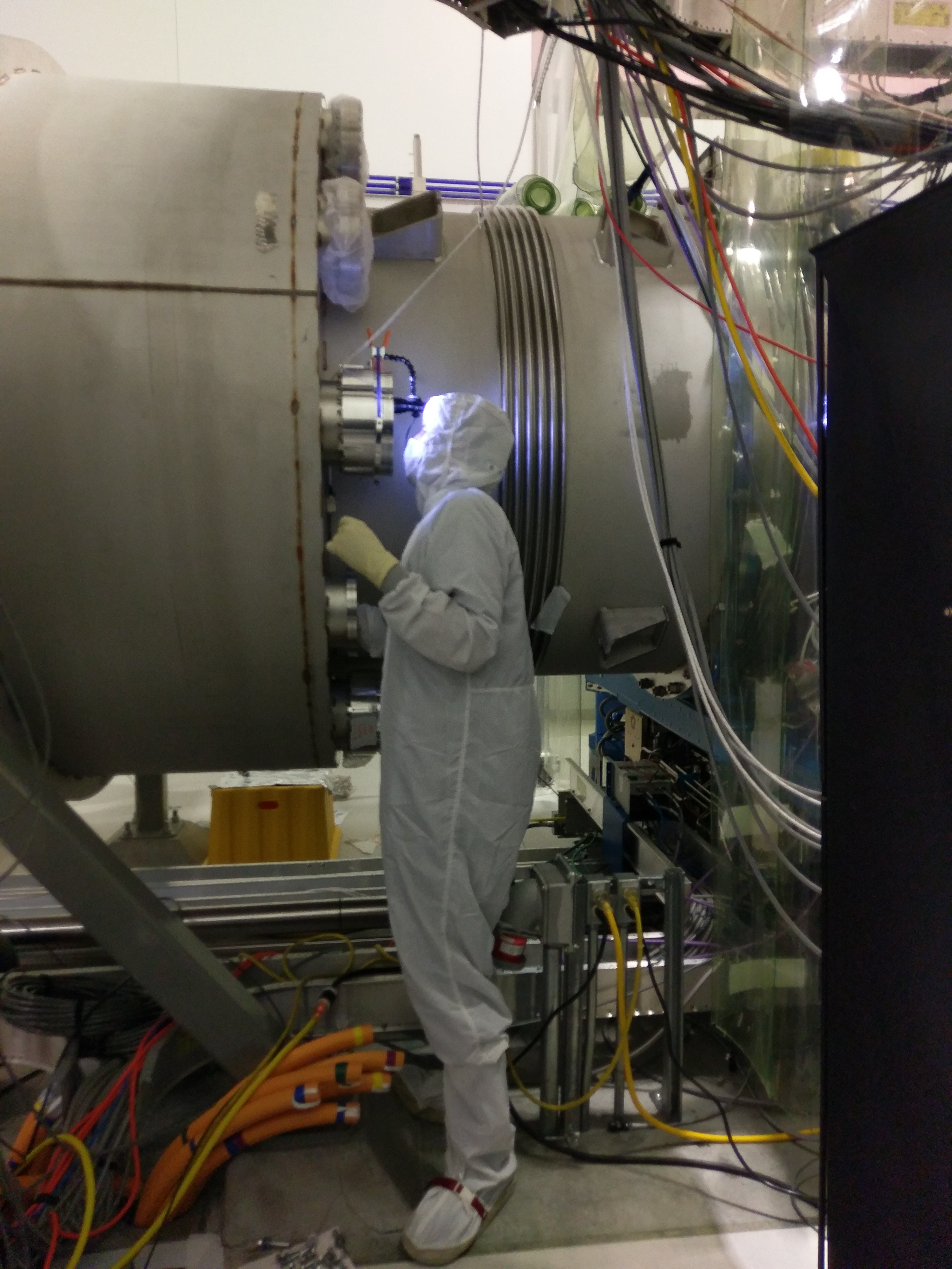
Gerardo, Vinny, Robert
First picture: Robert looking through the viewport at 9 o'clock position while inserting his hand into lower viewport hole at 8:00 position.
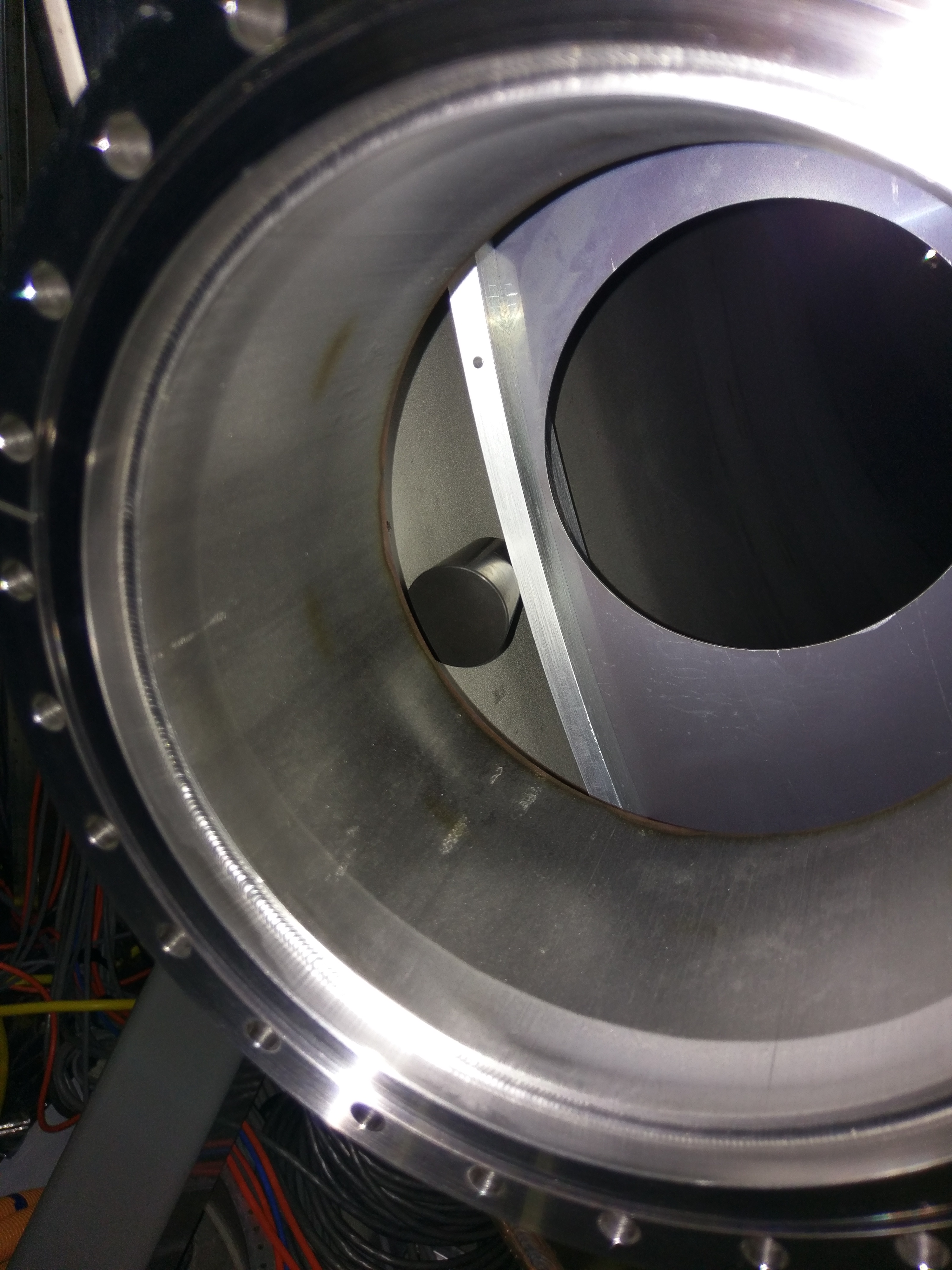
Second picture: A view through the lower viewport hole at 8:00 position. Black viton cork is inserted between the rib of the baffle and the chamber wall.
Pointer to the follow-up log entry: https://alog.ligo-wa.caltech.edu/aLOG/index.php?callRep=36147
Just to avoid any future confusion, the pictured location of the cork just above was not the final position. Based on feedback from the laser vibrometer, I moved it to 7:00, as pictured in the follow-up link given by Stephen.
