While HAM4 was open, I took a photo looking towards HAM5. I couldn’t quite reach safely down into the middle of the SR3 – BS path, so the attached photo was taken from just above that path. The photo shows a strong retro-reflection from the HAM6 septum. The septum is at a fairly small angle from the beam spots on the BS and SR2, is nearly normal to the beam, and is not vibration isolated like the other reflectors in HAM5. I think we want to include a baffle in our upgrade plans that keeps the septum from being visible from the BS or SR2.
[Kyle, Gerardo, Chandra]
After 20 hrs of rough pumping over two days, we transitioned to turbo pump (0.6 Torr). Before we leave tonight we will transition from QDP80 backing to scroll backing and decide if we need turbo water cooling. Tomorrow we'll turn QDP80 off and leak check HAM2 conflats.
Pressure currently at 0.4 Torr.
The Swiss Cheese Baffle, MCA1, has been identified as the worst scattering coupling site at LHO (https://alog.ligo-wa.caltech.edu/aLOG/index.php?callRep=35735 ). The baffle’s Q was so high that even minor damping was expected to significantly reduce its velocity. In addition, the baffle was accessible through ports in the reduction flange between HAM2 and the input mode cleaner tube, so the vent plan was modified at a late date to include damping of this baffle.
Before damping, I mapped out the motion of the baffle using the laser vibrometer. I was able to shine the beam through the camera ports beside the baffle at 3:00 and 9:00 and measure the motion of the suspension ring and the edge of the baffles (either side of the proposed dampers). I found that, at these locations, the baffle edge was, at 12 Hz, moving more than ten times as much as its support ring and about 1/3 as much as the center of the baffle. Measurements at multiple baffle locations suggested to me that the 12 Hz mode was a combination of a torsional mode around the shorter standoffs, a mode where the whole baffle moves back and forth in the beam direction within its suspension ring, and a bullet-like mode where the baffle moves somewhat more at the center. These measurements increased confidence that the selected locations were likely to work.
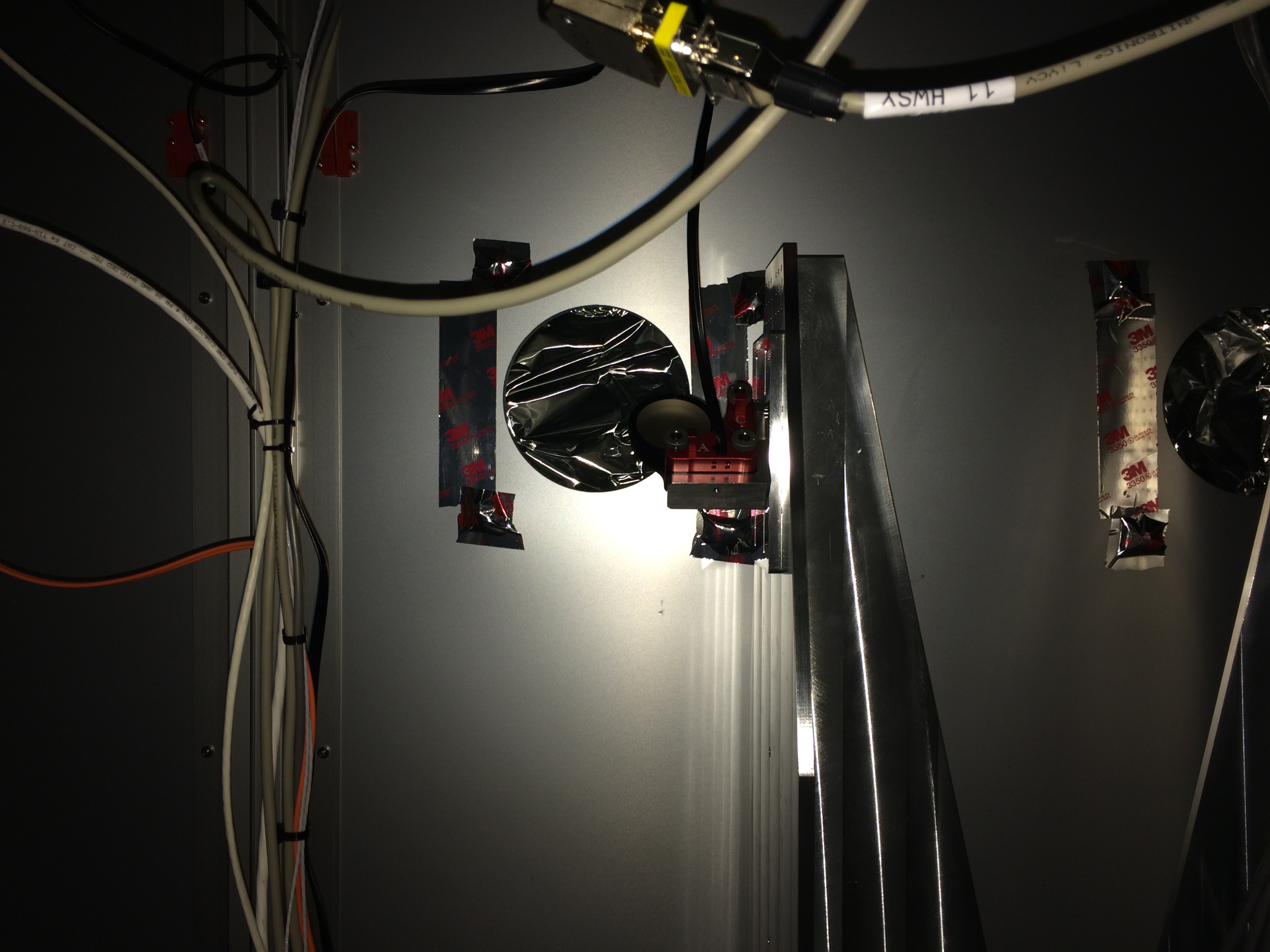
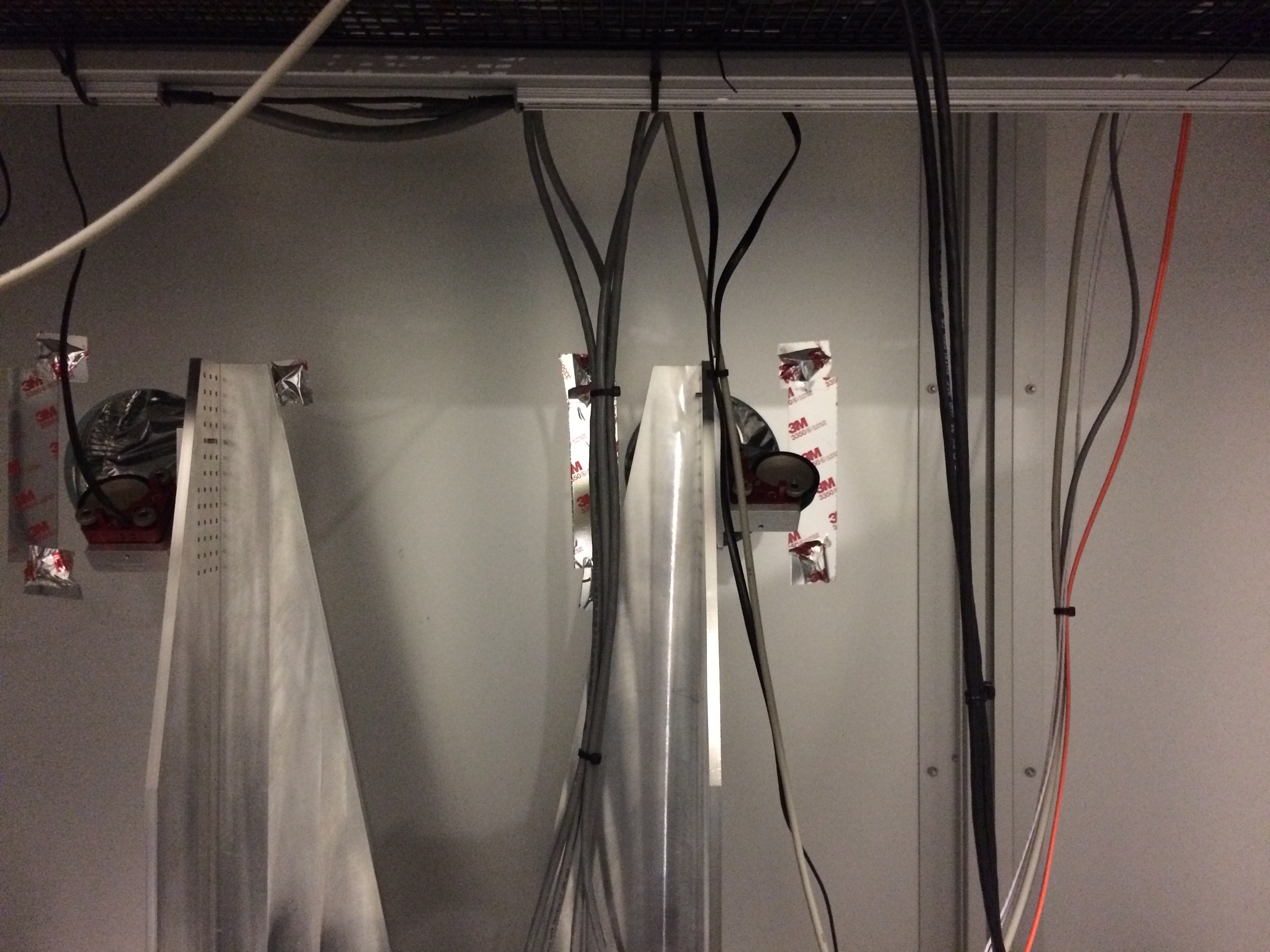
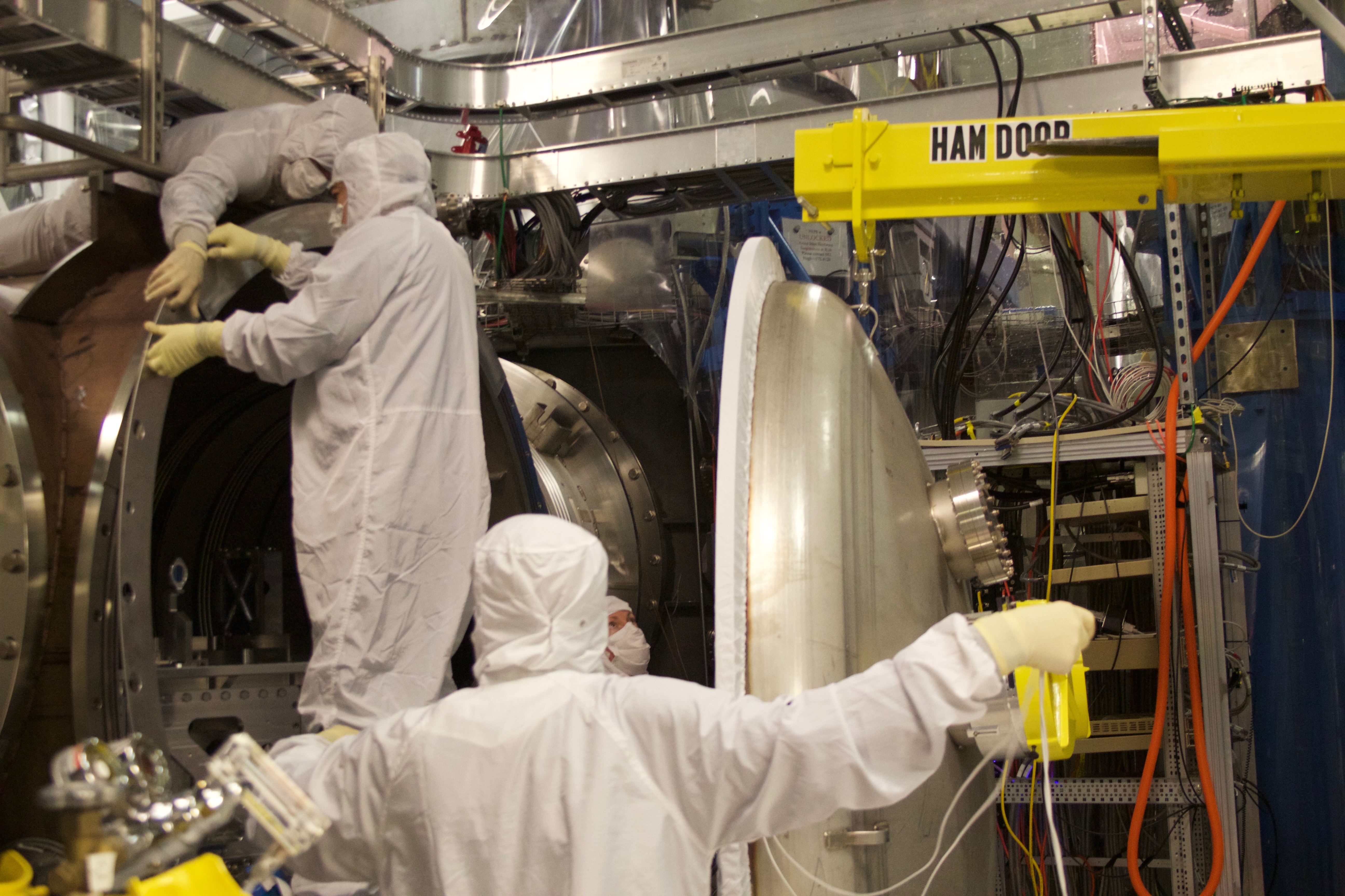
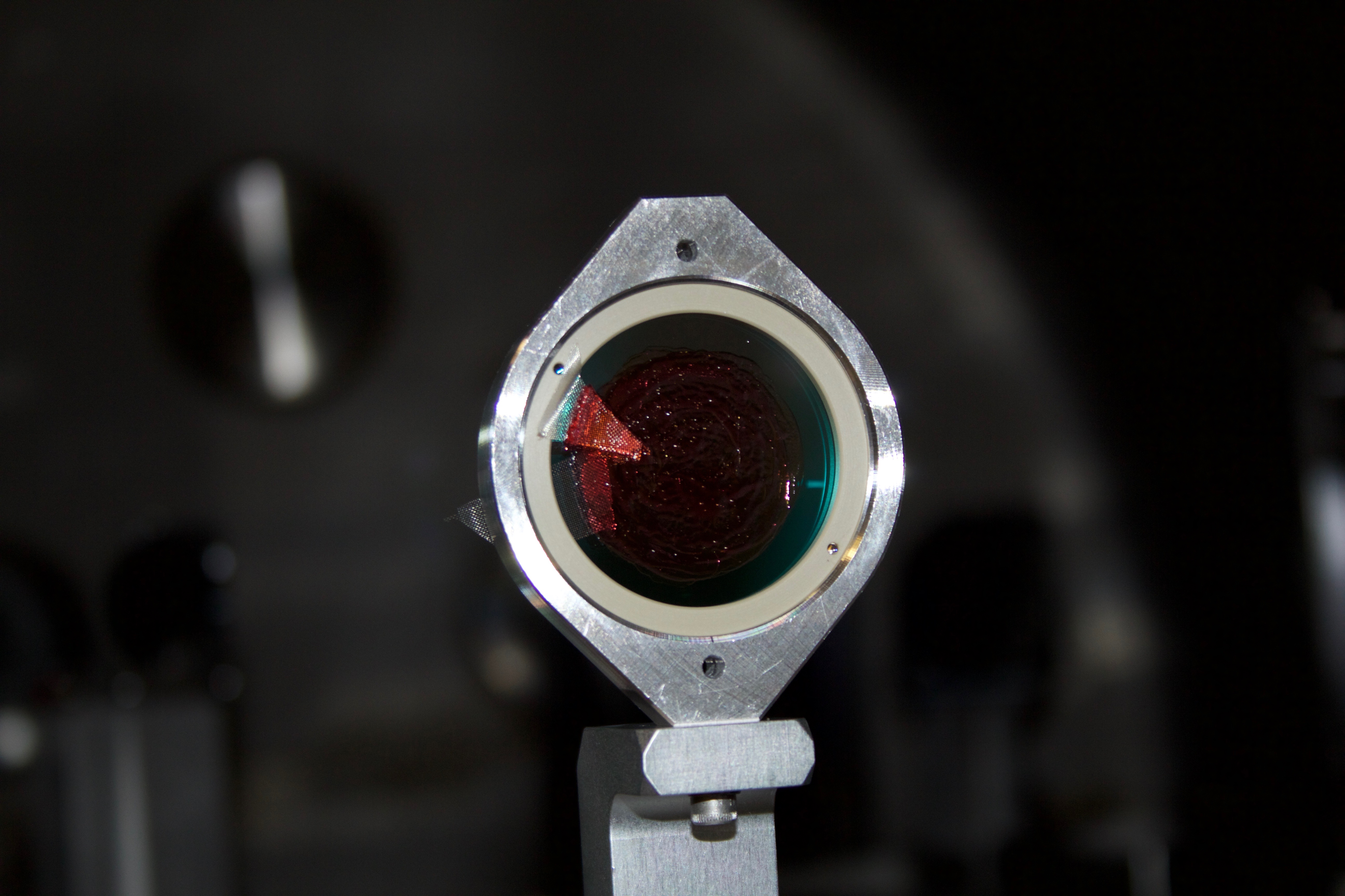
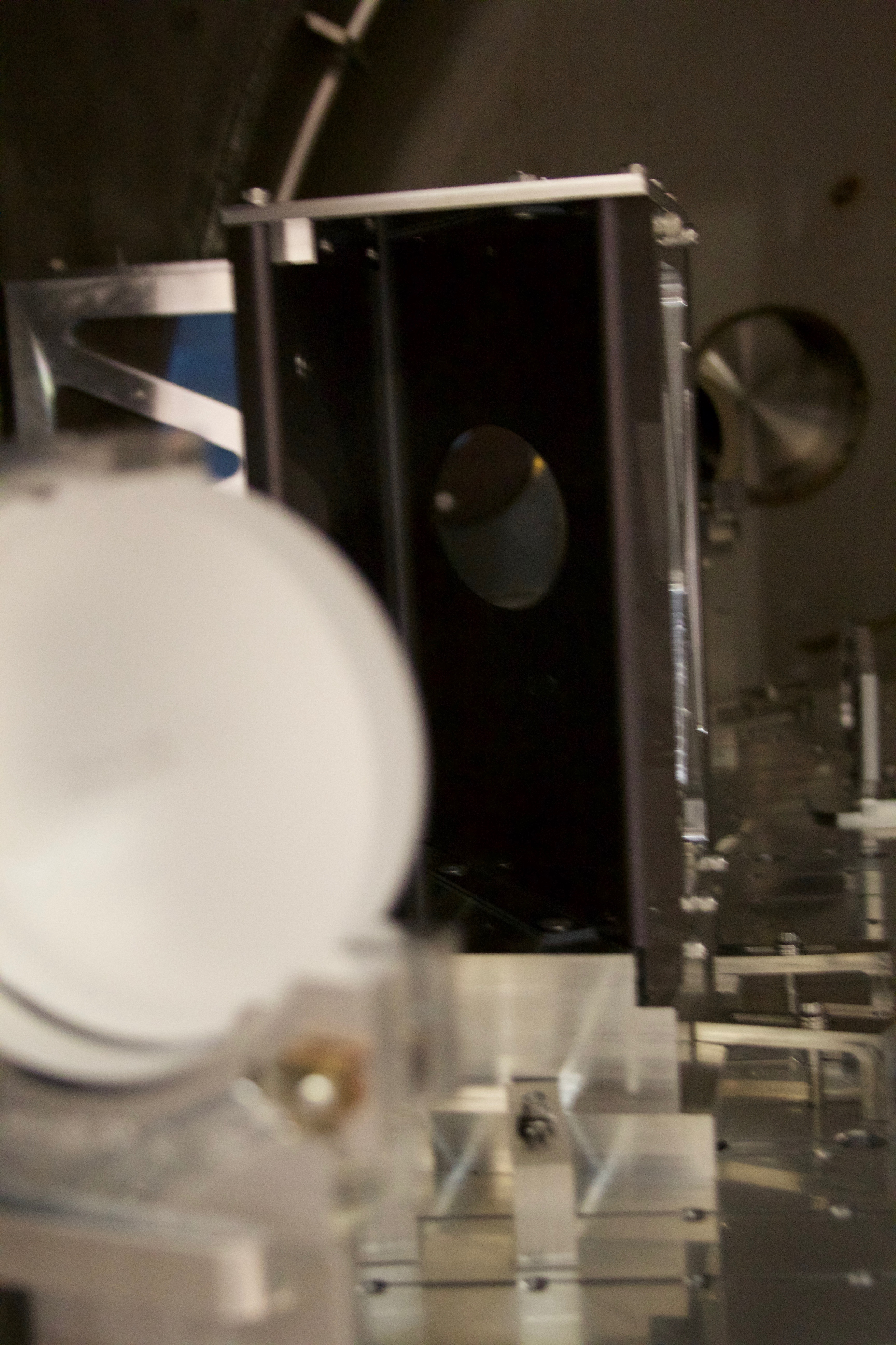
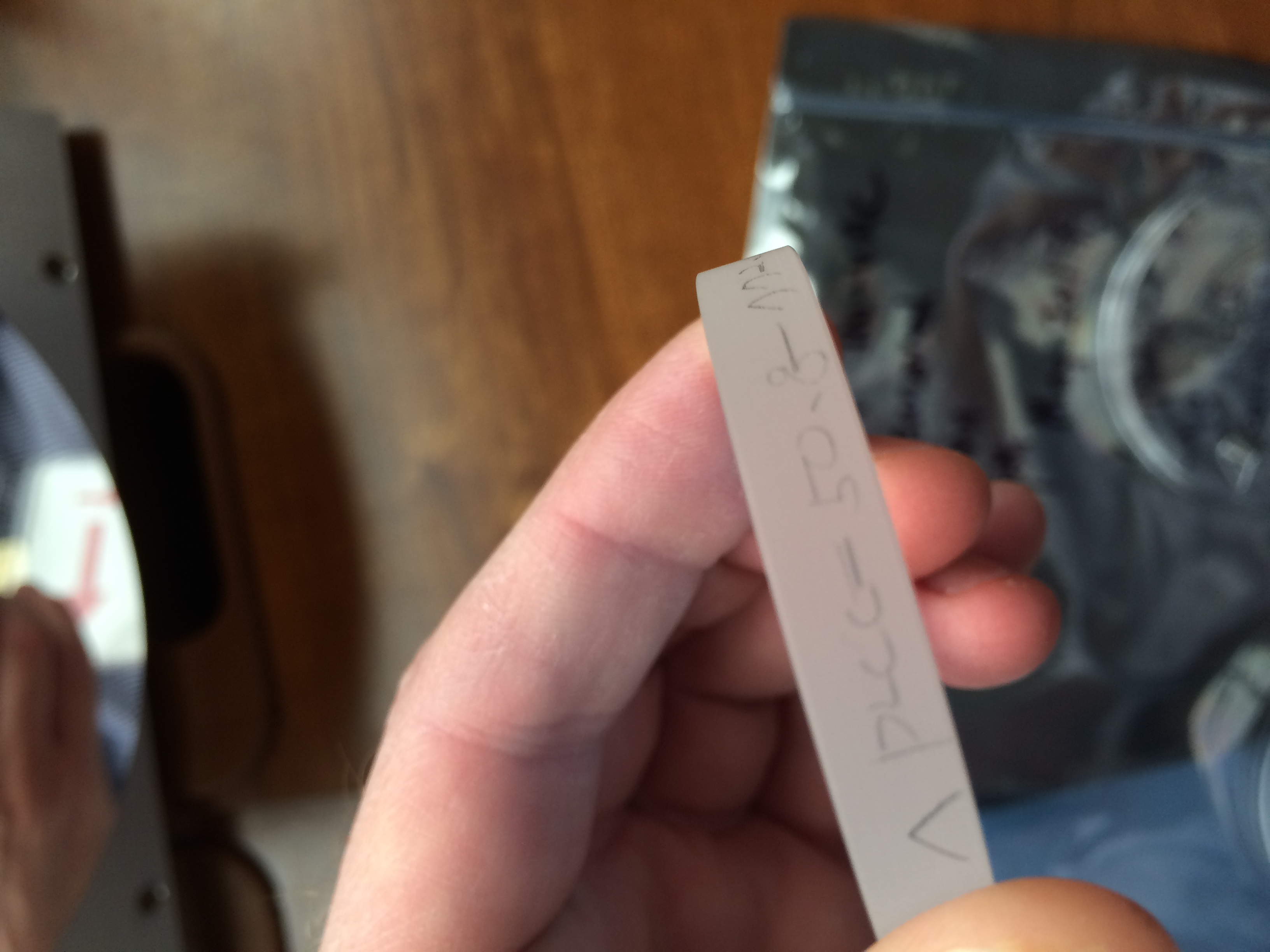
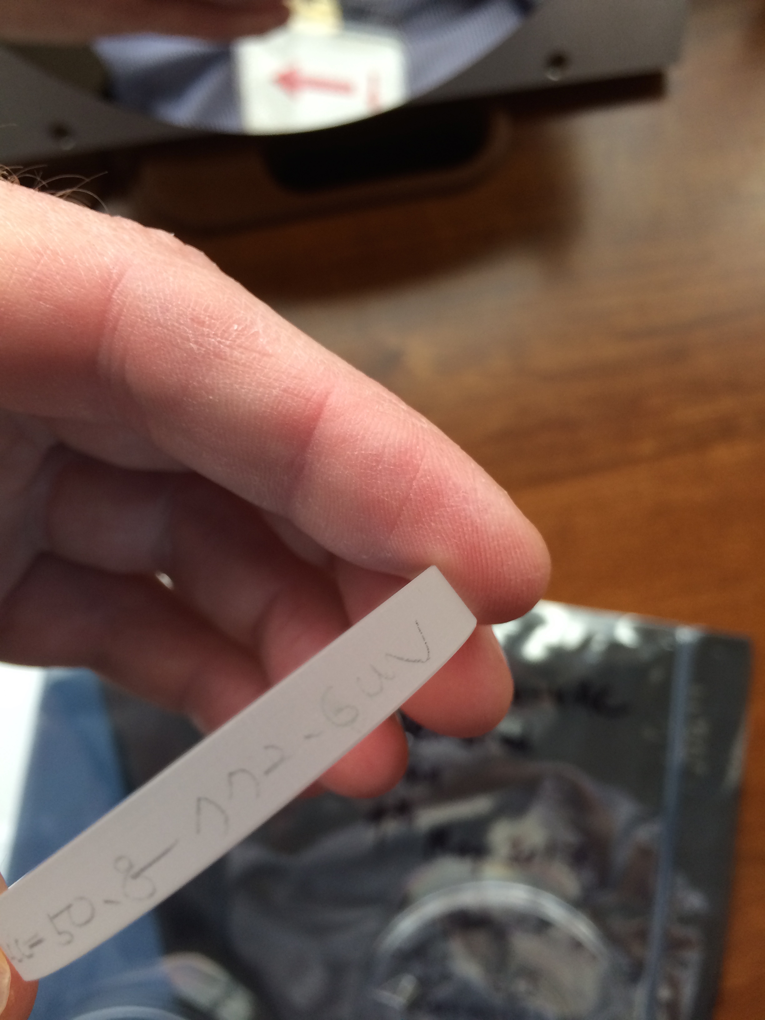
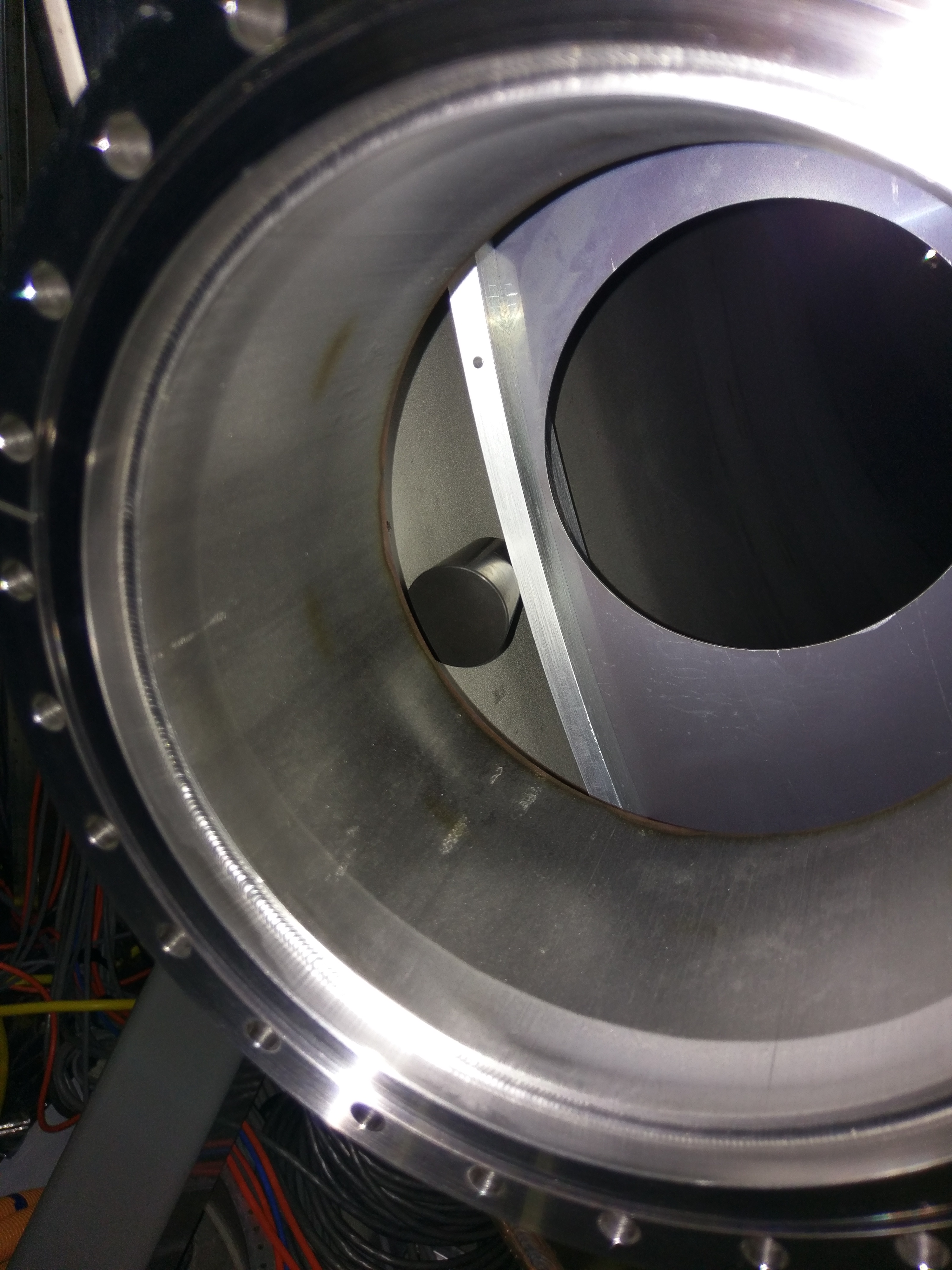
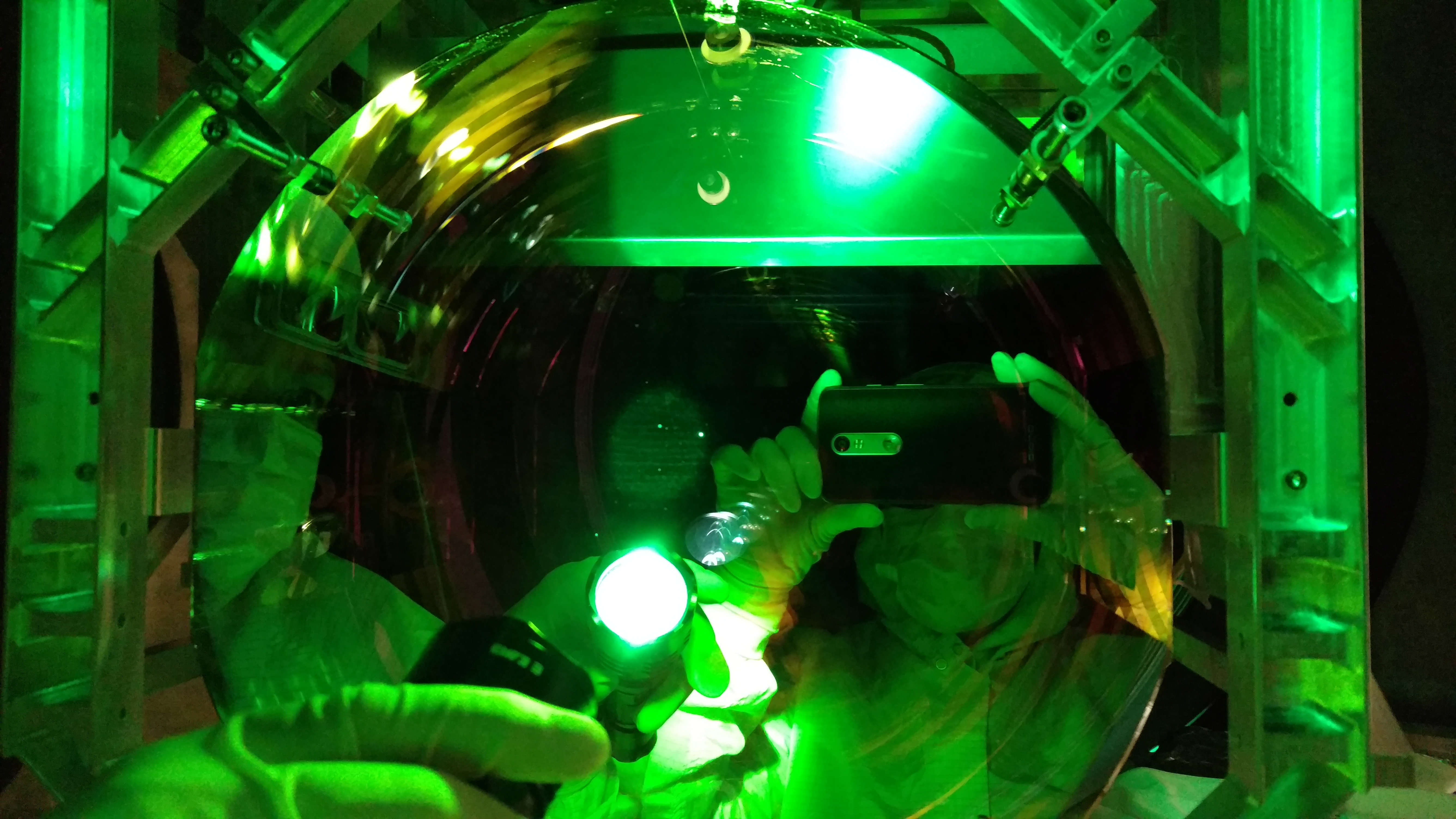
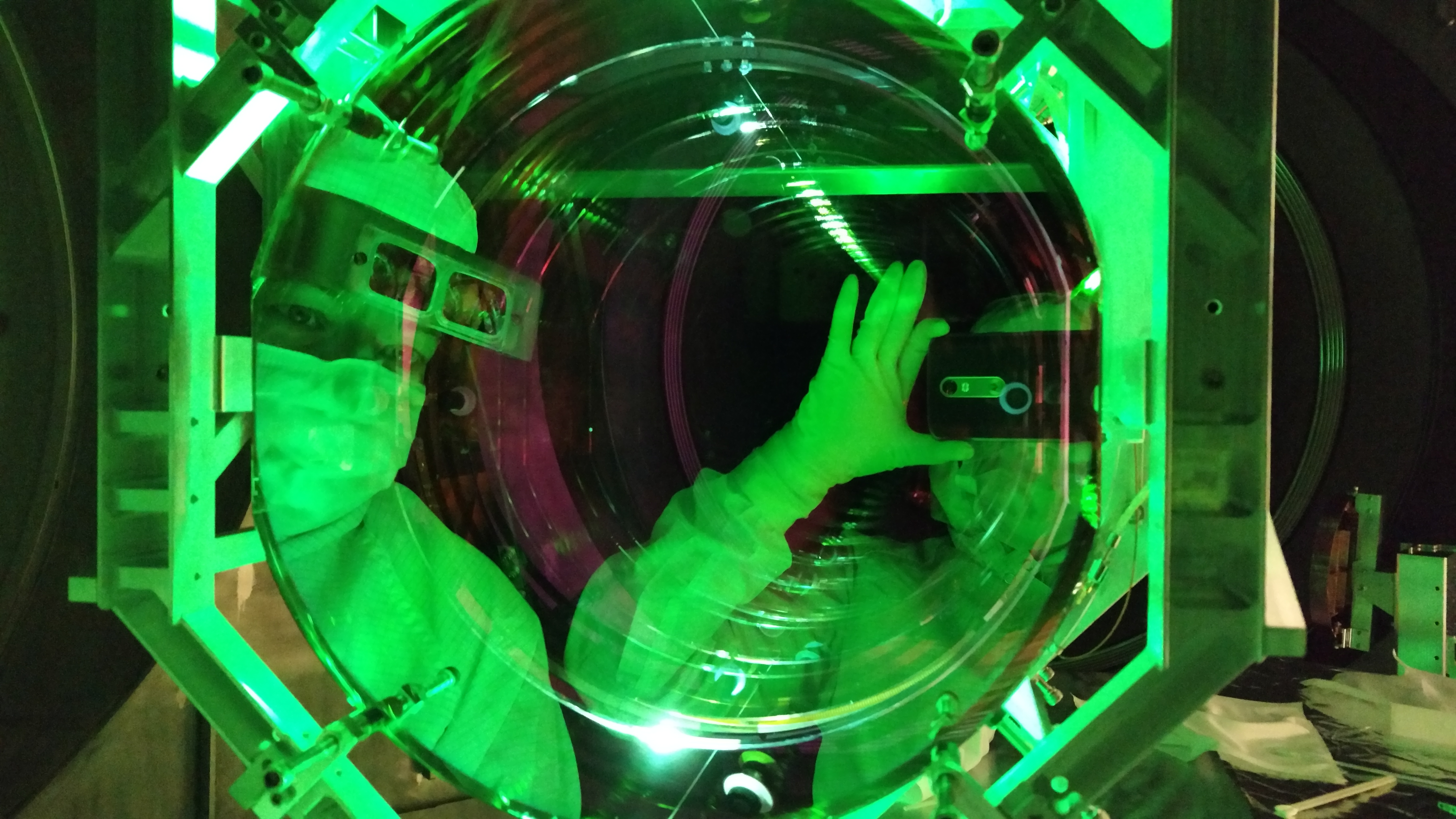
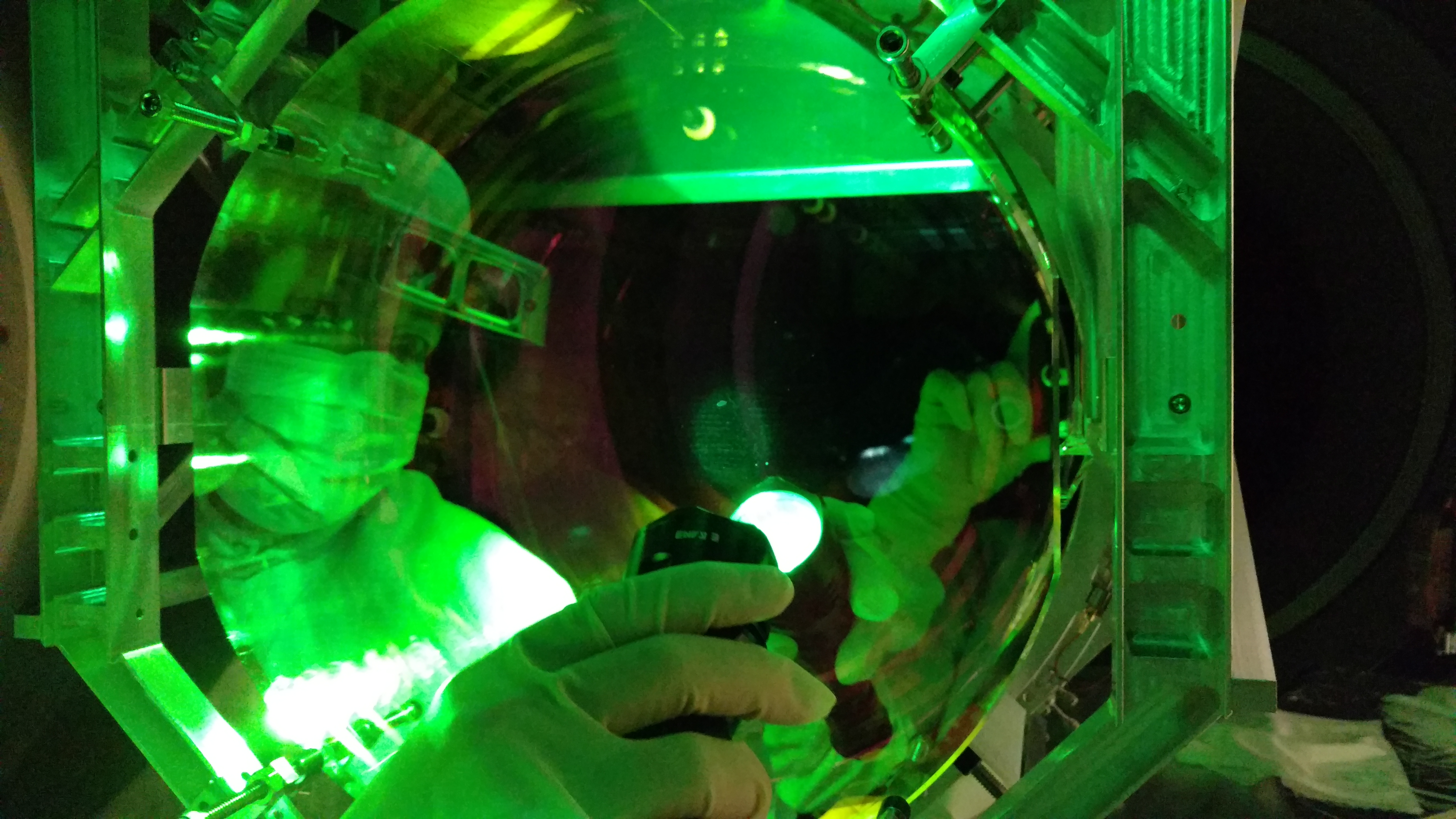
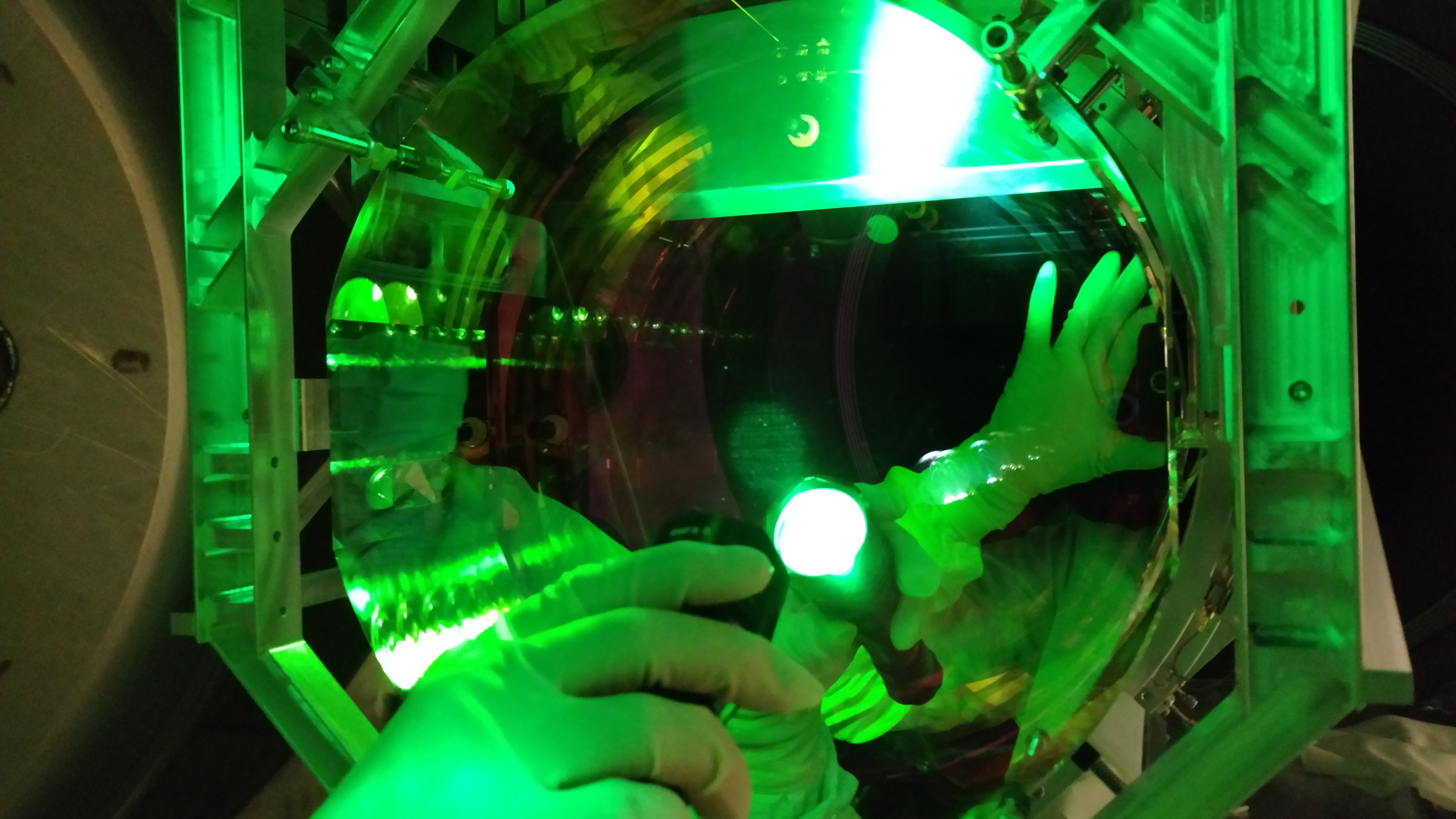
After doors had been put back on the open chambers, increasing purge air pressure, we pulled blanks covering ports at 4:00 and 8:00 (as viewed from the HAM2 side), one at a time. I reached in through the port at 4:00 and inserted a Viton HAM1 table spring (cork) between the baffle and the baffle support ring at about 3:00, viewable through the camera port (see Figure 1). At the port at 8:00, the baffle is closer than the support ring, so I reached up and through the hole in the baffle at 9:00 and inserted the cork from the HAM3 side. I put a third cork as far away as I could reach from the 8:00 port in the 6:00 direction, reaching about 7:00. Since the baffle and support ring are too far apart at this location for the cork, I inserted the cork between the baffle and the wall of the beam tube. We monitored the effect of each insertion with the vibrometer. The total time during which either port was open was under 45 minutes.
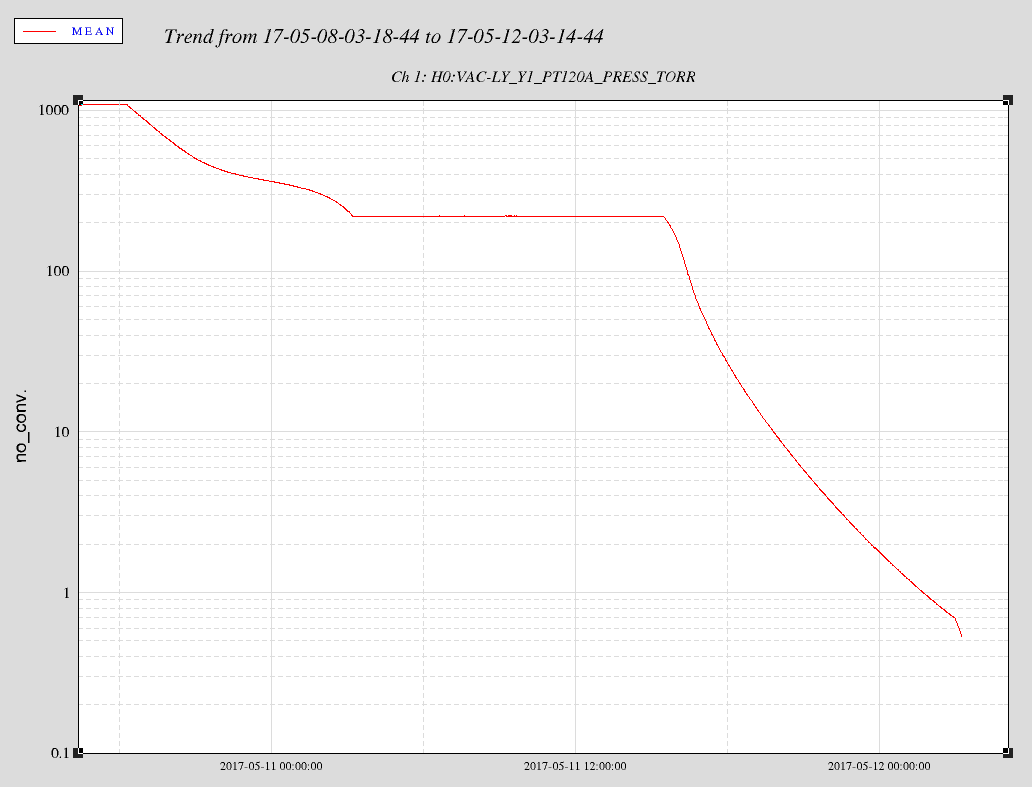
Figure 2 shows before and after spectra from the vibrometer and an accelerometer on the beam tube. Both sets were taken in similar conditions at air pressure. After damping, the 12 Hz peak was reduced to the degree that it no longer appears in the spectra for ambient vibration levels. To observe the peak I had to bang on the beam tube (lower plot). Other regions of the spectrum did not show new peaks. Of course the final evaluation will require time and DARM.
A simple damping scheme like this could be used on other off-table baffles: at least one of the Eye baffles is moving in the micron range.
Robert S., Calum T., Stephen A., Eddie S., Vinny R., Gerardo M.
HAM4 Annulus system was valved off at 23:45 utc, aux cart remains connected and running.
BSC3 Annulus system was valved off at 23:50 utc, aux cart remains connected and running.
If pressure maintains for both systems the vacuum aux hardware will be removed tomorrow.
WP 6635
FRS 8091
This morning the 24MHz RF oscillator source for EY showed a timing error. Chassis was powered cycled and timing error cleared. RF output levels for unit are within spec. Richard did noticed the readback signals for this unit were incorrect. Unit is currently in the EE lab for troubleshooting.
S1000581
The RF Source (24MHz) is now reinstalled at EY. Both the timing and readback signals errors have cleared.
1. Timing error for RF source EY was reported.
2. Unit was power cycled and timing fiber reseated. Unit locked according to front panel led lights.
3. The readback frequency, error, and control signal all displayed incorrect values in MEDM.
4. Looked at RF levels and frequency outputs. All within spec.
5. Unit was brought back to EE lab.
6. The input IC buffer on the timing interface 1 PPS locking board was replaced. We later convinced ourselves IC buffer never had an issue.
7. The FPGA on the timing slave was reprogrammed. We used the same Version 4 subversion 118 code.
8. Unit was reinstalled at EY. Unit locked within 5 minutes and all readback signals now show expected values.
F. Clara, R. McCarthy, M. Pirello
WP 6624
Field cabling to the Hartmann Table (ISCHT4) are reconnected. Things to note:
1. HWS cameras and new digital camera are on external power supplies. Same configuration as before vent.
2. Hartmann Sensor Power Distribution D1002206 - S1201877. Replaced led for negative 18V on rear panel.
3. Signal and power cables for Polarization PD Whitening Field Box inside the enclosure do not have a feedthrough panel.
WP 6625
ECR E1600210
The Kepco HV power supplies for ITMX, ITMY, and ETMX were replaced with an equivalent linear supply made by Mid-Eastern Industries Inc. Power supplies for ETMY were replaced on Dec 5 2016. Alog 32186.
New units installed:
S1700114 & S1700115 ITMY/ITMX
S1700116 & S1700117 ETMX
S1610431 & S1610433 ETMY
Units at EY are S1610431 & S1610432. Previous entry with S1610433 is incorrect.
TJ, Aidan
We realigned the HWSX and HWSY on-table optics today. For both X and Y we ran through the alignment in the following procedure:
Right now we're ready to inject the beams into the vacuum system. We won't be able to do this until the viewport covers are removed.
We also confirmed that both HWS cameras are accessible:
H1HWSMSRH1HWSMSR1
TITLE: 05/11 Day Shift: 15:00-23:00 UTC (08:00-16:00 PST), all times posted in UTC STATE of H1: Planned Engineering INCOMING OPERATOR: None SHIFT SUMMARY: Vacuum pumping of the vertex was resumed this morning. Chandra and Kyle are currently leak testing GV7 (WP 6636). Aidan and TJ worked on the HWS table. They are currently waiting for Chandra and Kyle to finish before resuming. (WP 6629) The LVEA was switched from laser safe to laser hazard and back to laser safe. The FMCS channels at end Y are no longer valid as a result of the FMCS upgrade. Jeff, Jason and Peter worked in the PSL enclosure to clean up routing of cables and plumbing (WP 6628). The fire department was on site and tested audible alarms. There is a timing error at end Y. Filiberto has pulled the RF oscillator source for troubleshooting. LOG: 14:56 UTC Marc -> mid Y (parts) end Y (timing system) 15:17 UTC Gerardo to LVEA to start pumps 15:19 UTC Apollo at end Y (as reported by Richard) 15:41 UTC Filiberto to end Y 15:45 UTC Richard to end Y 15:55 UTC Jeff to PSL enclosure (cable untangling) 16:09 UTC Filiberto and Richard back. Powercycled timing VCO chassis. Timing is back. 16:13 UTC TJ transitioning LVEA to laser hazard 16:17 UTC TJ done. Aidan to LVEA to start work on TCS table 16:24 UTC Marc back 16:24 UTC Jason to join Jeff and Peter in PSL enclosure 16:28 UTC Chris retrieving helium bottle from BSC7 16:36 UTC I went into the server room and plugged in the power for PSL enclosure phone per Peter's request. 16:43 UTC Fire department through gate, turning around to go to LSB 16:45 UTC Karen to LVEA and optics lab to clean 16:49 UTC Filiberto back from cabling hartmann table 16:51 UTC Christine to LVEA to clean 17:02 UTC Gerardo checking on turbo pump 17:05 UTC Filiberto to end Y 24 Mhz OCXO 17:10 UTC Hanford testing fire panel 17:14 UTC Gerardo back 17:43 UTC TJ and Aidan back from HWS table 17:44 UTC Hugh to end stations looking for serial numbers 17:55 UTC Gerardo back to LVEA to check on turbo pump 18:01 UTC TJ to PSL chiller to fill when instructed by Jason 18:10 UTC Filiberto back 18:17 UTC TJ done 18:19 UTC Aidan and TJ back to table 18:26 UTC Mike taking guest on tour in LVEA 18:27 UTC Karen out of LVEA, to mid Y 18:48 UTC Jeff B. out of PSL enclosre, Peter and Jason taking power measurements 18:54 UTC Mike and guest out of LVEA 19:02 UTC Karen leaving mid Y 19:21 UTC Peter and Jason done 19:29 UTC Kyle to mid Y 19:30 UTC Hugh back from outbuildings 19:46 UTC Filiberto to end Y (timing) 19:51 UTC Kyle back 20:16 UTC Betsy to take transfer functions of SUS 20:24 UTC Aidan and TJ back 20:33 UTC Hugh to LVEA, getting serial numbers off equipment on BSC1, HAM6, climbing around chambers 20:41 UTC Betsy running transfer functions on ITMX 21:22 UTC Hugh done on BSC1 21:44 UTC Hugh done 21:55 UTC TJ transitioning LVEA to laser safe for Chandra to climb on gate valve for leak testing. 22:12 UTC TJ done 22:41 UTC Fire department done 22:46 UTC Cheryl to optics lab Peter powered phone for PSL enclosure back off 22:59 UTC Cheryl back 23:03 UTC Marc to LVEA to photograph gatevalve leak testing 23:10 UTC Apollo leaving for the day
Yesterday we moved the ISCHT4 (Hartmann sensor) table back in position next to HAM4. Because of the on-going pumping on the vacuum system, the viewport covers remained in place and the light pipes remained disconnected. We spent several hours getting all the cables carefully hooked up again to the table.
We also noticed that the persicopes are severely out of position relative to the holes in enclosure (both shifted about 2" to the right). It's not immediately clear why this is the case but since the enclosure and periscopes are all bolted to the table, it is not a result of the table move. It may be that the table has been out of position for a long time and the periscopes were moved to capture the green beams that exit the vacuum system. Once we get access to the viewports, this should become clearer.
We also installed the nominal HWSY AIRLENS, PLCX-50.8-515.1-UV (per Table 2, T1000179-v20), replacing the lens installed to compensate for the incorrect vacuum lens.
There were a few needing N2 but they were only ones that had slowly been approaching action level over time, some that were just marginally okay, and a few that lost charge as we struggled to get the gauge to seal. These had not been checked since Oct '16 and none were at action level. Closing FAMIS 4596.
Measured the NPRO output power using a Gentec Pronto-250 (S/N 233415) power meter. After the conglomerate of optics after the NPRO but before the phase correcting EOM the power was measured to be 1.36W. Going into the power amplifier, 0.90W. The output of the monitoring photodiode at this time was 0.708V. This is the number reported by the laser MEDM screen. Jason / Peter
- Gerardo started vacuum pumps - Fire department testing onsite - Filiberto, Marc, Richard investigating timing error at end Y - LVEA transitioned to laser hazard, TJ and Aidan working on TCS table - Jeff B., Peter and Jason cleaned up cabling and piping in PSL enclosure
8pm local time
Vertex pressure is 92 Torr at turbo station and 220 Torr at pirani gauge (not accurate). Valved out QDP80 roughing pump for the night as a chamber safety precaution. Will resume roughing down tomorrow morning.
Powered down Kobelco purge air skid.
Leaving site now.
Stuff that needs to be replaced or fixed:
Correction: pirani gauge is PT120A (not PT120B)
(Aidan B, Corey G, TJ S, Jim W, PLUS much assistance to by Vacuum Team, Betsy W for prep work, & Jeff B. for staging of Contamination Control supplies)
All times in PDT
On Tues (May9th) multiple in-vacuum tasks were on the docket for work on H1, and this log covers the work at/inside HAM4: Replacement of the H1 HWSY VAC LENS. While performing this work, we followed Vent Plan (E1700124) & followed STEPS #32 - 39. Also used the Chamber Entry & Exit Procedure (E1201035, sheet4). Attached are some photo highlights from this job (all photos are on resourcespace [links below]).
HAM4 was roughly open from 10am - 2pm with only minimal entry within the chamber (access was from the North & only arms/upper body entered the chamber for this work task).
NOTE: During this activity there was an Alert/Site Area Emergency event on the Hanford site (first time this has happened for LHO in ~20years of being here).
| 0.3um (particle/L) | 0.5um (particle/L) | |
|---|---|---|
| Before Door Removed | 68 | 12 |
| After Door Removed | 5 | 1 |
| In-Chamber | 11 | 4 |
The new lens is from the bag (and box) labeled: CVI PLCX-50.8-360.6-UV-700-900, per Table 2 of T1000179-v20

The old lens had a label penciled onto the side. This read: PLCC-50.8-772.6-UV
This confirms our educated guess back in October 2014: (T1400686, page 2).


Installed the filter mounts under the PSL table. Given the tangle of cables and plumbing it will be necessary to rework this area to relieve the strain and entanglement of these cables and plumbing. A separate work permit will be filled for these activities. The photos below are of before and after mounting the filters.
Damping completed and flanges back on. No hitches. Three viton corks are in, preliminary laser vibrometry looks good. More later.
Gerardo, Vinny, Robert
First picture: Robert looking through the viewport at 9 o'clock position while inserting his hand into lower viewport hole at 8:00 position.
Second picture: A view through the lower viewport hole at 8:00 position. Black viton cork is inserted between the rib of the baffle and the chamber wall.
Pointer to the follow-up log entry: https://alog.ligo-wa.caltech.edu/aLOG/index.php?callRep=36147
Just to avoid any future confusion, the pictured location of the cork just above was not the final position. Based on feedback from the laser vibrometer, I moved it to 7:00, as pictured in the follow-up link given by Stephen.
GariLynn Billingsley, Travis Sadecki, Betsy Weaver, Calum Torrie, Nicki Washington (and a BIG support crew)
ITMx inspection with green light and portable microscope revealed several scattering sites. The center most sites were located high and right of center. (Camera images will be attached soon.) One of these (the brightest / closest to center) is shown in the attached picture. It measure roughly 0.5 mm across the halo.
There were many scatter sites of the same character all the way out to the edge of the optic. At the edge we attempted to clean one of these sites using the following solvents (IPA, Acetone, red FC and clear FC) without success.
Following this local cleaning and the overall inspection we then cleaned the entire HR face as per normal procedures i.e. with red first contact (FC) spray along with the cone etc ....
Subsequent inspection showed no change to these scatterering sites.
For full chamber report see alog by Betsy.
GariLynn and team.
A few more pix of various "spots" we saw on the HR surface of ITMX today which did not come off with cleaning.
The first shows 2 very visible spots near the center of the optic which are the "halo" shaped nature that Calum/GariLynn show zoomed in above.
The second picture shows a small damage spot on the lower left of center on the HR surface that we believe has been on the optic since processing/coating/fabricating. This is a surface penetrating feature visible with back-illumination, and is the only one observed of it's kind.
The third picture shows a much different "feature" far right of center, that is not anywhere else on the optic, but interesting.
Here's one more picture of us illuminating the section of the ITMX-HR slightly below and right of center where we DIDN'T find much during inspection.
We did see similarly described "donuts" on the BS-HR - see Kates alog and Betsy's attempt at pictures in ~2014:
https://alog.ligo-wa.caltech.edu/aLOG/index.php?callRep=12876
Need to review to confirm related!
Calum
Now with the BS picture attempts during the time frame of Kate's alog:
https://ligoimages.mit.edu/?r=24661
https://ligoimages.mit.edu/?r=24659
Here are the articles I mentioned in the SYS call this morning. These are not the same, as they describe a short, intense burst of light on a clean surface, rather than the suspected culprit of a CW beam on a bit of dust. Never-the-less, perhaps they will useful or interesting.
Morphology of femtosecond-laser-ablated borosilicate glass surfaces
Adela Ben-Yakar, Robert L. Byer, Anthony Harkin, Jacqueline Ashmore, Howard A. Stone, Mengyan Shen, and Eric Mazur
Citation: Appl. Phys. Lett. 83, 3030 (2003);
doi: 10.1063/1.1619560
View online: http://dx.doi.org/10.1063/1.1619560
View Table of Contents: http://aip.scitation.org/toc/apl/83/15, Published by the American Institute of Physics
Femtosecond laser ablation properties of borosilicate glass
Adela Ben-Yakar, Robert L. Byer
Citation: Journal of Applied Physics 96, 5316 (2004);
doi: 10.1063/1.1787145
View online: http://dx.doi.org/10.1063/1.1787145
View Table of Contents: http://aip.scitation.org/toc/jap/96/9, Published by the American Institute of Physics
I've included a picture of some of the craters from the second paper (fair use)
Facts: Nothing was found where we were looking for the absorber, low and right from center on the HR surface. Aidan's plot showed ~25 mm down and ~25 mm Right. No particulate was seen standing proud of the HR surface. Nothing was found on the AR surface of the adjacent CP. The features found on the ITM HR surface were of uniform size ~0.5 mm, with no more than 50% variation in size. All of the characteristic spots were circular. There were various dark (uncontaminated?) shapes in the center of the circles - keyhole, linear, dot or uniform (filled) Features were found all over the optic including the very edge - Can’t say if there were any off the coating or not. No immediately apparent distribution. tried the following cleaning on a spot at the bottom edge of the optic to the left of the bevel damage. (in order) Acetone - scrub with cotton swab IPA - scrub with alpha swab DI water - scrub with alpha swab Windex - scrub with alpha swab clear first contact paint red first contact paint Within estimated beam waist we found 7 circular features counted 1 spot (very small) penetrating the coating (glowed when illuminated from behind) - believed to be present as polishing defect. Silica wafer, mounted parallel to ITM03, but low of the arm cavity baffle: no similar scatterers - only small particulate. 1” optic mounted perpendicular to ITM03 on the side of the compensation plate suspension structure: no similar scatterers - only small particulate. Speculation: Possible vaporization of particulate depositing on the surface. Possible contamination underneath the HR coating, present all along. Further investigation at: https://dcc.ligo.org/T1700193
Particle counts during the in-chamber work were taken a few times:
2:30pm PT during first contact work with 1 person in the chamber, 2 people just prio
| Count Size | 10am PT entrance to chamber - Jim was starting ISI locking, 1 person in chamber | 2:30pm PT during first contact work with 1 person in the chamber, 2 people just prior |
| 0.3um | 9 | 135 |
| 0.5um | 2 | 82 |
| 1.0um | 2 | 24 |
BSC3 DOOR WAS OFF FROM ~9am to 5pm PT.