Sheila, Jason, Evan G, Krishna
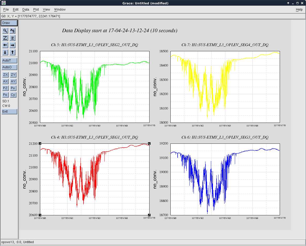
Mode hoping of the ETMY oplev has been showing up in hveto since April 19th, although the oplev damping is off. The glitches that show up are definitely glitches in the sum, and the oplev is well centered, so the issue is not that the optic is moving. There is a population of DARM glitches around 30 Hz that is present on days when the oplev is glitching but not on other days. We are curious about the coupling mechanism for these glitches and wonder if this coupling could be causing problems even when the oplev is not glitching loudly .
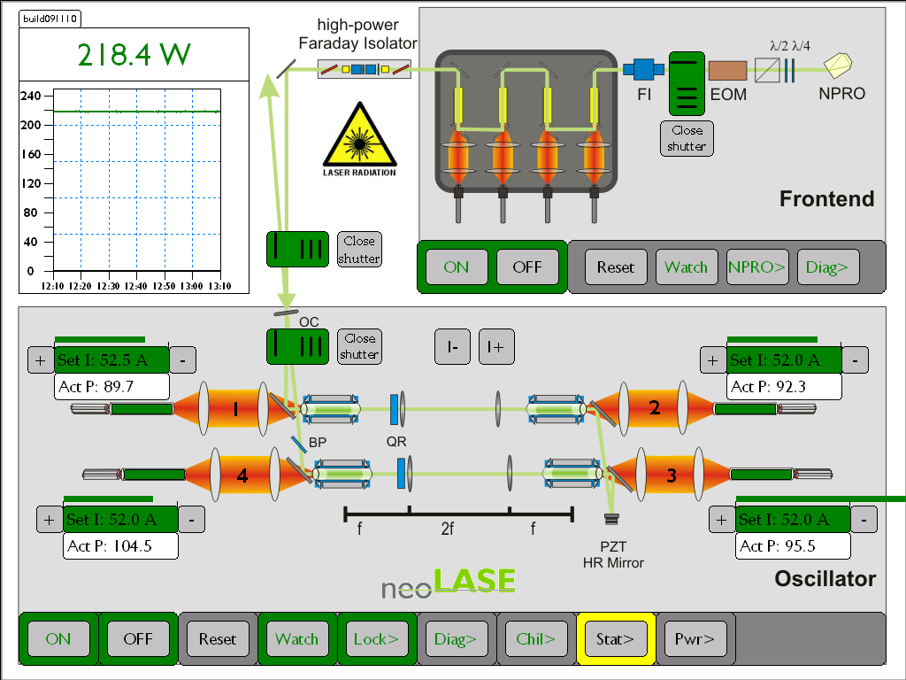
Evan, Jason and I connected the monitor on the oplev laser diode power to one of the PEM ADC channels used to monitor sus rack power (we used H1:PEM-EY_ADC0_14_OUT_DQ, which was monitoring the +24V power and is channel 7 on the field rack patch pannel. Jason can make the laser glitch by tapping it, with this test we saw clear glitches in the sum but no sign of anything in the monitor so this monitor might not be very useful. Plugging this in means that the lid of the cooler is slightly open.
We also unplugged the fiber, so that for the time being there is no light going into the chamber from the oplev. If these glitches are coupling to DARM electromagnetically, we expect to keep seeing them in DARM. If they were somehow coupling through the light (radiation pressure, something else), we would expect them to go away now. One glitch that we looked at is about a 75 uW drop in the laser power on the optic. (A=2P/(c*m*omega^2)= 3e-19 meters if all the power were at 20 Hz). We don't really know how centered the beam is on the optic, or what the reflectivity is for the oplev laser, but it seems like radiation pressure could be at the right level to explain this.
Using an ASD of the oplev sum during a time when the oplev is quiet, this noise is more than 3 orders of magnitude below DARM at 30 Hz.


Keita writing as Corey.
ASC -> Jenne, Sheila and others. Locked IFO needed.
EY oplev -> Jason. IFO status doesn't matter.
Additionally, the following might happen.
OMC jitter measurement -> Sheila, locked IFO.
Removing/putting on Hartman plate on the end station HWF camera when the IFO is unlocked -> Nutsinee.