WP6590 Gather Ubuntu12 workstations from outbuildings and LVEA
Richard, Carlos:
All ubuntu12 workstations were removed from the LVEA and VEAs and are stored in the CUR awaiting OS upgrade to Debian8.
WP6594 NDS2 client update
Jonathan:
Actually the new NDS2 client 0.14 was made the default for matlab.
WP6577 Read out new FMCS data using the BacNET EPICS IOC
Patrick, Carlos, Dave, Buba, John
EPICS FMCS channels which are now being montored by the new FMCS system were removed from the old IOC (h0epics) and added to the new IOC (fmcs-epics-cds). Due to a difference in the way binary data is handled, the cell phone text alert configuration was changed and restarted. This change is being propagated to the MEDM screens by Patrick.
Carlos installed the new server in the MSR, it spans the CDS-SLOW (10.105) and the FMCS (10.2) networks, talking BacNET on the FMCS network, and EPICS on the SLOW network.
WP6603 Rack up 4th DMT computer
Dan, Carlos, Dave:
An iLIGO Sun X2200 was racked up in the MSR (second DAQ rack) above h1dmt2. This will be configured as the fourth DMT machine (h1dmt3) and be used as a test system.
WP6602 Downgrade DMT calibration/hoft code
Greg, Aaron, John Z.
The DMT code was downgraded to the version as-of three weeks ago. This is a temporary status while the new code is made ready for release.


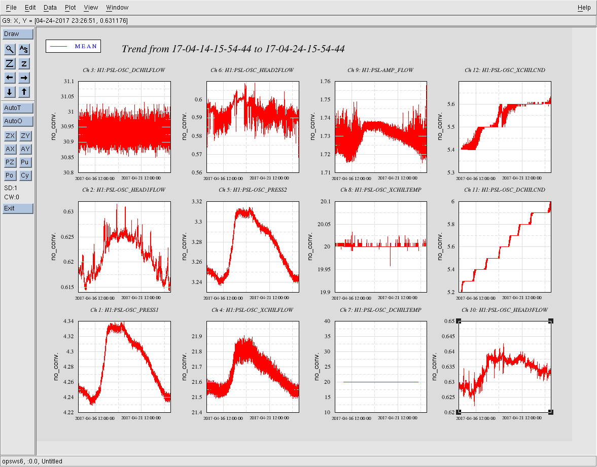
Pressure build at the vertex due to closure of GVs.