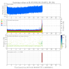
By driving a line in CARM at 400 Hz we saw that the 9 MHz demod phase was mistuned by 9° at 2 W of PSL power. We tuned the demod phase to within 0.5° and then powered up.
Once the interferometer reached its final power (44 W), we could see that the demod phase was again mistuned, this time by 5°. Over the course of 30 minutes it relaxed to ~0.5° of detuning.
TCS-X: Levels OK. TCS-Y: Added 200ml (low = 6.5, fill = 8.5)
TITLE: 10/16 Day Shift: 15:00-23:00 UTC (08:00-16:00 PST), all times posted in UTC
STATE of H1: Lock Aquisition
INCOMING OPERATOR: Jeff
SHIFT SUMMARY: Locked for most of my shift, last 30min it broke. To keep it locked when the range has drifted to ~35Mpc, adjust SRM to minimize POP90. Seemed to help get a 10Mpc and keep it locked. Evan H. has been doing some work, and we are on our way back up now.
LOG:
I wanted to find out how much contrast defect light we have in DARM at the moment. It seems to be about 2.0(5) mA at the moment. Since we run with 20 mA of total photocurrent, this implies a homodyne angle that is mistuned by about 6° away from the nominal value of 90°. I did not check how stable it is over the course of several hours.
To measure the contrast defect, I watched the height of 332 Hz pcal line in DARM while varying the dc offset.
Also, I found that the DARM residual is microseism-dominated at 50 W of input power (the current blrms is about 0.5 µm/s). So I turned on a boost in FM6 of LSC-OMC_DC. We should incorporate this into the DARM filter modules.
Expanding more on Evan's methods here: Optical gain values in [mA/pm] were obtained by taking the magnitude of the transfer function at 331.9 [Hz] between H1:CAL-PCALY_RX_PD_OUT_DQ (pre-calibrated into [m] / zpk([],[1,1],1)) and H1:OMC-DCPD_SUM_OUT_DQ (pre-calibrated into [mA] to ~10% accuracy). Total light on the OMC DCPD values in [mA] were pulled directly from H1:OMC-DCPD_SUM_OUT_DQ (again, pre-calibrated into [mA]). The DARM DC offset was varied by adjusting the "fringe offset" or H1:OMC-READOUT_X0_OFFSET (pre-calibrated into [pm] to ~20-30% accuracy). This EPICs record can be found on the "IFO DC READOUT" sub-screen (called OMC_DC_READOUT.adl) of the OMC_CONTROL.adl overview screen. The nominal value is 10.65623 [pm], and to obtain the above data Evan varied the DARM DC offset from 6 to 13 in 1 [pm] increments. zeta = homodyne angle [rad] = arccot( contrast defect [mA] / total light on DCPDs [mA] ) where the contrast defect [mA] is the y intercept of the parabola. The subsequent IFO optical gain vs. DC power on the DCPDs was then fit (by-eye) to blind/simple quadratic function with a DC offset. to arrive at the answer. From Evan's presentation G1601599, which nicely distills the famous-yet-cryptic 2001 Buonnano&Chen paper, the response of a DRFPMI interoferometer using detuned resonant sideband extraction can be parametrized into a pair of complex poles (for the optical spring, at frequency |p| and quality factor Q), a pair of real poles (for the coupled cavity, or "RSE" pole, at frequency xi) and zero, at frequency z, which can potentially (and typically does for low detuning) cancel one of the RSE poles: dP 1 + i f / z -- = g * --------------------------------------- (5) dL (1 + if/|p|Q + (f/|p|)^2) - (xi / f)^2 The zero, in his presentation, is composed of the following fundamental parameters, cos(phi + zeta) - r_s cos(phi - zeta) z = f_a * ------------------------------------------ (8) cos(phi + zeta) + r_s cos(phi - zeta) where f_a is the arm cavity pole frequency (assumed to be the same for both arms), phi is the SRC detuning phase, and zeta is the homedyne angle. One of the outputs of the above measurement, is that, if the homodyne angle, zeta, is consistently 90 +/- 6 [deg], then we can used Eq. (8) to simply fix the zero frequency in the overall IFO response (5), assuming the arm cavity pole frequency and SRC detuning phase also remain constant. This would reduce the parameter space over which the calibration group would have to MCMC in fits to measurements of the overall response (e.g. LHO aLOG 28302). However, (1) This is, again, *one* measurement of the homodyne angle, zeta. We're going to have to measure it multiple times, and quantify the uncertainty in the estimate better, to make sure that we're confident it stays there. (2) The SRC detuning phase, phi, and the arm cavity pole frequency, f_a, also need measuring with quantifiable uncertainty. These are also parameters believed to be fixed, but the question is always to what level. f_a has been measured before to be ~83 Hz, using several techniques (e.g. LHO aLOG 7054), but rarely with quantified uncertainty. Further, those measurements are typically taken of a single cavity, and there is worry that the pole frequency may change a bit in the full IFO due to different spot centering*. The detuning phase "can be determined by the spring frequency." To me, this is quickly going down a rabbit hole of another independent MCMC parameter estimation fitting regime, but I'm still quite ignorant on the topic. *word on the street is that LLO has a technique, once in full lock, of "kicking the SRM fast enough" such that full IFO remains locked but simple as an PRFPMI. I couldn't find an aLOG on it, and these discussions with Evan today were the first I'd heard of it. Worth exploring!
Doing a real least square fit gives different results, depending on what you assume
TITLE: 10/16 Day Shift: 15:00-23:00 UTC (08:00-16:00 PST), all times posted in UTC
STATE of H1: Lock Aquisition
OUTGOING OPERATOR: Travis
CURRENT ENVIRONMENT:
Wind: 21mph Gusts, 15mph 5min avg
Primary useism: 0.05 μm/s
Secondary useism: 0.44 μm/s
QUICK SUMMARY:
Looks like Guardian took it all the way up on its own after Travis left, and it has stayed locked for 2.5hrs. The range drift still looks the same.
TITLE: 10/16 Owl Shift: 07:00-15:00 UTC (00:00-08:00 PST), all times posted in UTC
STATE of H1: Lock Aquisition
INCOMING OPERATOR: TJ
SHIFT SUMMARY: Made it to Increase_Power a couple of times during lulls in the wind. Had to reset the Noise Eater a few times and struggled with FSS locking again. At the beginning of my shift, Sheila suggested that if the wind doesn't get better, it may be futile to stay and try locking. Being a bit stubborn, I decided to give it a while, but with the wind still in the high 30s and predicted to get worse as the day wears on, I am giving up. I'll leave the request at NLN and hope that it will be locked when TJ arrives, but no promises.
LOG:
Evan, Sheila, Jenne
The overall message: looking at refl control and IMC control signals leads to different conculsion about our frequency noise, but we can slightly improve our DARM noise at high frequencies by engaging an additional boost in the IMC. The sensing noise should be large enough to see on the DBB, so it would be helpful to get the DBB running again.
IMC control signal suggests a lot of excess IMC sensing noise:
Yesterday afternoon Evan and I looked again at the frequency noise as seen in IMC control signal. The attached screenshot shows the IMCF spectrum with and without CARM locked.
We think that when the mode cleaner is locked the IMC control signal should be the sum of:
Once CARM is locked, it will be the sum of:
Between 100Hz and 1kHz, the noise stays in the same with and without CARM locked, so this noise should be either laser noise or ref cav sensor noise imposed by the laser. The noise which goes away when we lock CARM should be IMC sensing noise or VCO noise. Since there isn't any frequency where locking CARM increases the noise in IMCF, this measurement gives us an upper limit on the REFL9 sensing noise.
We think that the IMC shot noise should be abot 15uHz/rt Hz, the ref cav shot noise should be about 0.4mHz/rt Hz, and the shot noise on refl 9 should be about 5uHz/rt Hz at 1kHz, increasing as f. The second attached png shows the measurements for IMC with and without the mode cleaner locked, the estimated levels of shot noise we would expect to see in there and in maroon an estimate of the where the IMC loop noise should appear when CARM is locked. If you believe that and make a projection to the light blue and maroon traces are IMC sensor noise and make a projection to Watts on refl 9, then to DARM using the measurements posted here, I predict a noise in DARM of around 1-2e-21 m/rt Hz at 100 Hz. There are several things that don't quite make sense, the projection doesn't agree with the measured REFL9 spectrum or Evan's estimate of the REFL 9 spectrum using the refl control signal (those things don't agree with each other either).
The refl control signal tells a different story:
Tonight, Jenne and I tried engaging boosts in both the IMC and CARM. The third attached screenshot shows that the refl control signal was reduced when we added a boost to the IMC, both peaks at around 1 kHz and the higher frequency noise. This means that at these frequencies the frequency noise is not limited by sensing noise from REFL or the IMC, which contradicts the conclusion above. Not suprisingly, it looks like the peak at 280Hz is sensing noise from the IMC or REFL. In any case, we saw a small improvement in DARM at high frequencies by using the IMC boost, so we should probably make this a regular part of our locking sequence. Boosting the CARM loop (using the 40Hz/4kHz filter) didn't change anything in DARM.
Edit:
I've done a quick calibration of the REFL control signal by wathcing the IMC PDH signal at the point where the REFL AO path gets summed in. We have about 2.4Vpp there (at 2Watts, with 16 dB of gain), using the IMC cavity pole of 8812Hz, Alexa's quick PDH calibration in 7054, -24 dB AO path gain, and 0.00061Volts/count, REFL control has about 0.1413 Hz/count. I've added this to the front end filter for REFL control. Now we can plot the IMC and refl control signals together. At 1kHz, we expect a supression of about 200 without the IMC boost on, so the noise at 1kHz makes sense as laser frequency noise or ref cav sensing noise.
Daniel and I had another look at the calibration of REFL control, and sorted out some factors of 2.
Just to be clear: I measured the IMC ODH signal at out1 with 2 Watts into the IMC and the loop disengaged. We get 2.4V pp for the error signal, measured after 15dB IN1 gain. The attached matlab script has a simple model of the IMC loop without taking into account the FSS gain, with the gain at the point where the AO signal is added is 3.67kHz/Volt. However, when we transition to analog CARM, we reduce the fast gain by 6dB and add 6dB gain to the in1 gain slider, so in full lock the calibration is 1.86kHz/Voltat the summation point. This will have to be updated if we change the IMC IN1 gain in full lock other than scaling it for input power changes.
The calibration is now in the refl control filter:
anti whitening: Two zeros at 100Hz, two poles at 10 Hz, DC gain of -6dB. This previously had a DC gain of 0dB, which was not correct because the input is differential.
cnts2Volts: 6.1e-4
-24dB of AO gain (this will have to be updated if we change this)
imcV2Hz: 1836 Hz/V at the point where the IMC error signal is summed with REFL control. (probably too many digits here)
Title: 10/15/2016, Evening Shift 23:00 – 07:00 (16:00 - 00:00) All times in UTC (PT) State of H1: IFO is locked at NOMINAL_LOW_NOISE, 48.0W Intent Bit: Observing Wind: Ranging from a Gentle to a Fresh Breeze (8-24mph 0.03 – 0.1Hz: Z & Y running around 0.8um/s; X at 0.04um/s 0.1 – 0.3Hz: All elevated to around 0.3um/s Outgoing Operator: TJ Activity Log: All Times in UTC (PT) 23:00 (16:00) Take over from TJ 23:25 (16:25) Set Intent Bit to Commissioning 01:08 (18:08) Checked TSC chillers. X OK. Added 300ml to Y 01:13 (18:13) Lockloss – Commissioning. IFO had been locked for 6.5 hours 01:23 (18:23) Sheila - Going to PSL rack area to make measurements 01:38 (18:38) Sheila – Out of the LVEA 04:35 (21:35) Lockloss – Commissioning 05:25 (22:25) Reset Fiber Polarization down to 2 06:30 (23:30) Environmental conditions are deteriorating. No luck relocking. IFO in DOWN 06:31 (23:31) Shelia – Going into LVEA to work on MC 06:52 (23:52) Sheila – Out of the LVEA 07:00 (00:00) Turn over to Travis Shift Details: 10/15/2016, Evening Shift 23:00 – 07:00 (16:00 –00:00) All times in UTC (PT) Support: Jenne, Sheila Incoming Operator: Travis Shift Summary: IFO locked at start of shift. Jenne is commissioning. After lock loss, kept IFO down so Sheila can run some MC measurements. After relocking, just before 03:00 (20:00), PI modes 18 & 26 started to ring up. It took many iterations to get the modes to start to come down. When they were coming down they would hit a point just above the 1 line, drop straight down, then bounce back up. For a while the bounce backs were getting smaller and smaller. However, after a few minutes they started to ring back up. After many more tweaks both modes started to come down. After about 20 minutes both modes disappeared into the noise. Environmental conditions were improving until about 05:00 (22:00), when the second round of storms start to move into the area. Winds are back up from Moderate Breeze (around 15mph) to Fresh Breeze (high 20s). Gusts are in the Gale to Sever Gale range (34 to 47mph). Both seismic bands are correspondingly elevating. To paraphrase W.C. Fields “It’s not a fit night out for man nor beast, or interferometry”.
After relocking, just before 03:00 (20:00), PI modes 18 & 26 started to ring up. It took many iterations to get the modes to start to come down. When they were coming down they would hit a point just above the 1 line, drop straight down, then bounce back up. For a while the bounce backs were getting smaller and smaller. However, after a several minutes, they both started to ring back up. After many more tweaks both modes started to come down. They were still dropping just before the 1 line, and then bouncing back up. The trend was downward and after about 20 minutes both modes disappeared into the noise.
I tuned the Xarm TCS, eventually down to 0W. Recall that the Yarm TCS is already at 0W at high PSL power.
This consistently made my frequency coupling and jitter coupling lines better. My intensity coupling line went through a bit of a minimum, but didn't come up very far from that.
We started the next lock with 0W TCS, and it still seems good. When the SRM is optimally aligned to minimize POP90, the peaks around a few hundred Hz are a little smaller. But, if the SRM moves even a bit, they come back to their usual height. On the one hand, this is good, since it means the peaks are better when the sideband buildups are better (previously it has seemed like the peaks are better when the SRC is slightly misaligned). On the other hand, it's not good that it's so sensitive to the SRM being perfect. We definitely need to close some kind of loop around the SRM, even if it's just the dither loop.
I'm obviously at the limit of how low I can go with the Xarm TCS, but it will be good to try increasing the Yarm CO2 a bit, to see if that also helps. I know it's a pain, but we may also want to think about increasing the ITMX ring heater even more, so that we have more room to move with the CO2.
In the attached plot, you can see my demodulated DARM signals (orange-ish yellow is demodulated DCPDs in all rows). Top row is the frequency line at 900 Hz, middle row is intensity line at 860 Hz and bottom row is pitch jitter line in the PZT on the PSL table at 820 Hz. Bright yellow in all rows is the ITMX CO2 power. You can see that things got a bit worse when I increased it from 0.24W nominal to 0.40W around -120 minutes, then better when I went to 0.1W around -80 min. Things continued to improve, although not much, when I went to 0W around -30 min. It's not clear why we lost this lock. For the intensity line in the middle row, you can see that it went through a minimum around about -65 minutes. Unfortunately I didn't have the demod-phase-zeroing servo on with enough gain for this loop until about -130 minutes, so we can't compare directly to the coupling that we had during nominal operation of 0.24W, but it doesn't get as bad as it was with 0.40W.
[Jenne, JeffB]
After our lockloss this afternoon, we couldn't get the ISS to quit oscillating. Eventually we were able to engage the loop using PD_B, and since the new PD_A location didn't seem to make a big difference in DARM, we left it on PD_B for this lock. Someone may want to revisit this on Monday.
Sheila & Jeff B. While the ISS was oscillating, Sheila dropped the gain from 30.0dB to 24.0dB and the ISS stopped oscillating. The ISS appears to be behaving better. Trending the gain showed on 10/11/16 the gain was changed from 18.0dB to 30.0dB. Over the past several Ops shifts, after a lockloss the mode cleaner, ISS, and FSS would be oscillating continuously during the green locking; breaking the lock. After many such attempts ALS would finally lock. Since Sheila adjusted the gain, it has taken a just a couple of tried to get past LOCKING_ALS. The MC, ISS, and FSS are now relocking more quickly after a Lockloss.
Checked the TCS chillers. X was OK. Added 300ml water to TCS-Y Raised level in site glass from 6.8 to 8.5. The mesh filter was seated properly in place.
Posted HEPI pump Trends (FAMIS #4525). Pressures for the 4 CS pump stations are flat around 100. The control voltage shows some fluctuations during the period, however day 1 and day 45 values are within a few 10ths of each other. Both end stations pressures and voltages are, by comparison, somewhat noisy. End X max pressure and min difference for the end points is 0.2. For End Y this same difference is 0.1. Between the measurement end points there is a more noise in both the min and max values. There is no apparent pattern to the fluctuations.
Sorry Jeff but these trends are just 10 minutes long.
TITLE: 10/15 Day Shift: 15:00-23:00 UTC (08:00-16:00 PST), all times posted in UTC
STATE of H1: Observing at 47.5928Mpc
INCOMING OPERATOR: Jeff
SHIFT SUMMARY:
Daniel points out that the behavior of REFL LF during the 9 MHz modulation depth reduction does not make sense:
One possible explanation is that the 9 MHz depth is a factor of 3 lower than we think it is. However, based on single-bounce OMC tests (described below), this seems to not be the case. So the discrepancy remains unexplained.
For the OMC test, I first turned up the modulation depth by 3 dB (the slider value is normally 16.8 dB during lock acquisition, so I turned it to 19.8 dB).
Then I locked the OMC on the carrier, and then each of the 9 MHz sidebands, and recorded the following data:
Frequency |
PSL power (W) |
OMCR A sum (ct) |
OMC trans sum(mA) |
Carrier | 9.8 | 600 | <0.01 |
82 | 14.6 | ||
USB 9 | 47.2 | 2930 | 0.01 |
2860 | 1.07 | ||
LSB 9 | 47.7 | 2920 | 0.01 |
2880 | 1.07 |
I assign an uncertainty of 10% to the OMCR and OMC trans sum values. The OMC visibility is not perfect here, but we can nonetheless roughly infer the modulation index. If the carrier measurement had been done at 47 W, we would have seen 70.6 mA of sum photocurrent. Since Psb/Pc ≈ Γ2/4, this implies Γ = 0.25 rad during this measurement. This implies a value of Γ = 0.17 rad during normal lock acquisition. This is within 30% of the old value measured with the PSL OSA (0.22 rad). In other words, we are not missing a factor of 3 in the modulation depth, so the behavior of REFL LF during lock acquisition does not make sense.
I am attaching more time series for what happens during 9 MHz modulation depth reduction.
The ~0.8% increase in the transmitted arm powers suggests a modulation depth during lock acquisition of about 0.13 rad. With this modulation depth, we'd expect a change of 2.0 mW on REFL LF during the reduction (instead we see 0.54 mW).
I made the following power measurements at 1.9 W:
RF9 | RF45 | REFL LF (mW) | AS LF (mW) |
16.8 | 23.2 | 0.315 | 69.7 |
13.8 | 23.2 | 0.271 | 68.5 |
13.8 | 20.2 | 0.236 | 49.1 |
I made the following measurements at 44 W, after reaching some kind of thermal equilibrium:
RF9 | RF45 | REFL LF (mW) | AS LF (mW) |
16.8 | 23.2 | 3.55 | 545 |
13.8 | 23.2 | 3.71 | 575 |
13.8 | 20.2 | 4.20 | 823 |
Note that (somewhat confusingly) REFL LF is calibrated into milliwatts on the diode itself, while AS LF appears to be calibrated into milliwatts exiting the AS port (i.e., before OM1).
We can use the REFL LF measurements to infer the carrier and sideband content both at 1.9 W and at 44 W. Here we assume the modulation depths have their nominal lock-acquisition values (16.8 dB for 9 MHz and 23.2 dB for 45 MHz, which based on old OSA measurements correspond to 0.22 rad and 0.28 rad of modulation depth). Additionally, we can scale the 1.9 W measurements to infer what we should see at 44 W, all other things being equal.
9 MHz (mW) | 45 MHz (mW) | Carrier (mW) | Total (mW) | |
1.9 W, from measurement | 0.088 | 0.070 | 0.157 | 0.315 |
44 W, from measurement | 0.64 | 0.84 | 2.55 | 4.02 |
44 W, scaled from 2 W | 2.04 | 1.62 | 3.64 |
7.30 |
Note the large 9 MHz discrepancy from the power-up.
I copied the RF slider values for the 44 W measurement wrong out of my lab notebook, so here is the corrected table:
RF9 | RF45 | REFL LF | AS LF |
10.8 | 20.2 | 3.55 | 545 |
13.8 | 20.2 | 3.71 | 575 |
13.8 | 22.2 | 4.20 | 823 |
The algebra and resulting numerical values for the PD sideband content were done correctly, though.
Sheila, Jenne, Kiwamu
Attached is a spectra of IMC-F in different configurations. (MC locked at different powers, DC readout, low noise) From 100 Hz to about 1 kHZ, the spectrum of IMC F doesn't change much at all in all of these different configurations. So the IMC control signal is not dominated by REFL9 sensing noise in full lock, and probably represents the real frequency noise at the input to the IMC.
We can do a better job later, but if we assume this is really frequency noise we can roughly calibrate this into Watts on REFL 9I:
At 1kHz: 0.1Hz/rt Hz Frquency noise arriving at IMC (which is roughly consistent with measurements in P1100192, Fig 8) Suppresion of IMC loop: 1/200 (alog 22188) Supression of CARM loop (alog 22188, our ugf is now more like 8kHz) roughly a factor of 1/30. We can scale the DC optical gain of 0.017W/Hz used in 22188 by sqrt(2) to account for the factor of 2 increase in input power and the 6dB modulation index decrease since then. Taking into account the coupled cavity pole at 0.5 Hz give another factor of 1/2000:
0.1Hz/rtHz(1/200 Hz/Hz IMC supression )(1/30 Hz/Hz CARM suppression) (0.024*0.5/1000)W/Hz = 2e-10 Watts/rt Hz signal on REFL 9I or 1.7e-5 Hz/rt Hz of residual frequency noise expected.
We can repeat this at 400 Hz:
0.03Hz/rtHz(1/600 Hz/Hz IMC supression )(1/300 Hz/Hz CARM suppression) (0.024*0.5/400)W/Hz = 5e-12 Watts/rt Hz signal on REFL 9I or 1.7e-12 Hz/rt Hz of residual frequency noise expected.
Comparing this to Evan's in loop measurement of the CARM noise using REFL control, (here) it is close at 1 kHz but not at 400 Hz. You can also compare it to the transfer functions from REFL 9I to DARM posted here, and see that at 1 kHz the expected frequency noise is of the order of 5e-20 m/rt Hz at 1 kHz.
The main message: It is probably worth making a projection for frequency noise in DARM using IMC-F to estimate the frequency noise after the ref cav, because a very rough estimate says it could be within a factor of 2 of DARM at 1kHz.
I just quickly tried changing gains on the FSS while watching the IMC F spectrum in full lock. The features from 100 Hz-1kHz do not change in IMC F as the FSS gain at these frequencies changed by 7 dB, so we are not limited by gain in the FSS at these frequencies. The FSS might have been oscillating at both the highest and lowest gain settings here.
The gain at 1kHz from the IMC should be ~50 (ugf at 50 kHz) * 20 (boost) / 2 (mismatch between filter/cavity pole) ~ 500.
If the IMC gain is near 70 KHz one can probably kick in the second boost.
The noise level at high frequencies is 20 mHz/rtHz. Assuming this is the IMC shot noise at 2W, It would be at 4 mHz/rtHz at 50W. The VCO noise is around 2 mHz/rtHz at 1kHz. What we see is more like 8 mHz/rtHz, about twice higher than expected. Reference cavity?
The noise floor seen in IMCF with only the mode cleaner locked does not seem to be IMC diode shot noise, since it doesn't change as the input power is increased.
Also, the REFL9I readback now agrees almost perfectly with the CARM control readback; not sure why (this was true even before changing the demod phase). The CARM error readback is still mostly junk.
I tried again to check for REFL sensing noise in DARM by reducing the CARM gain, it seems that we cannot reduce the gain enough to bring the ugf to a few hundred Hz without loosing lock. (I could reduce the gain by 8 dB, but not turn off the boost, the other day we turned off the boost first, were able to reduce the gain by about 4dB, then when we tried to reduce the gain by 3 more dB we lost lock.