TravisS, KarlT, PeterK, RickS
We captured several series of images with the exposure for each successive image about a factor of three higher than the previous image.
Attached are four multi-page .pdf files containing the photos with:
- Resonant Green only (ITM OptLev on)
- Resonant IR and Green (ITM OptLev on)
- Resonant IR at 2W incident (ITM OptLev off)
- Resonant IR at 20W incident (ITM OptLev off)
The camera settings for the images are in the fifth attached .pdf file.

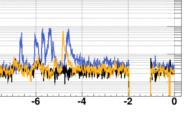
Is there any chance that these images are flipped left-right? If not, the bright spots seem to be in a position that is inconsistent with the position of the heat absorption, as shown in Aidan's alog 35336. According to Aidan's alog, the absorber is on the bottom right when viewing the ITMX HR side, however the bright spots here seem to be on the bottom left when viewing ITMX's HR side.