Following yesterday's alog 90219:
- IM2 and IM3 were reverted back to Monday evening position just using the slider values.
- Using flashes, confirmed that the IM4 trans as well as ISS QPD were roughly at the same position as the Monday evening position.
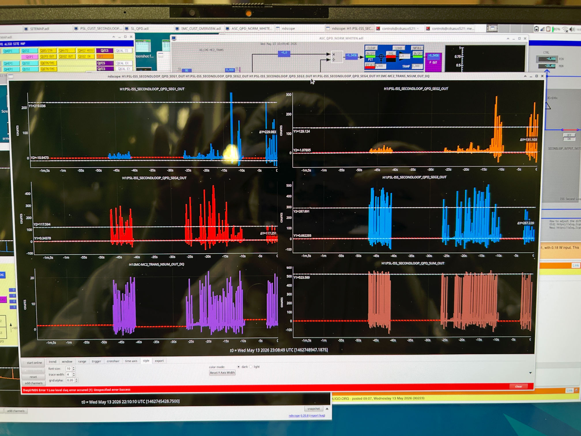
- Elenna confirmed that ISS OUTER SUM flash peak minus dark offset was 0.031 with 200mW input. (INNER SUM was much smaller.) Back in March it was 0.062 with 2 W input. So somehow the alignment into ISS array used to be REALLY poor.
At this point I and Rahul checked the beam positions in HAM2. Some things to note:
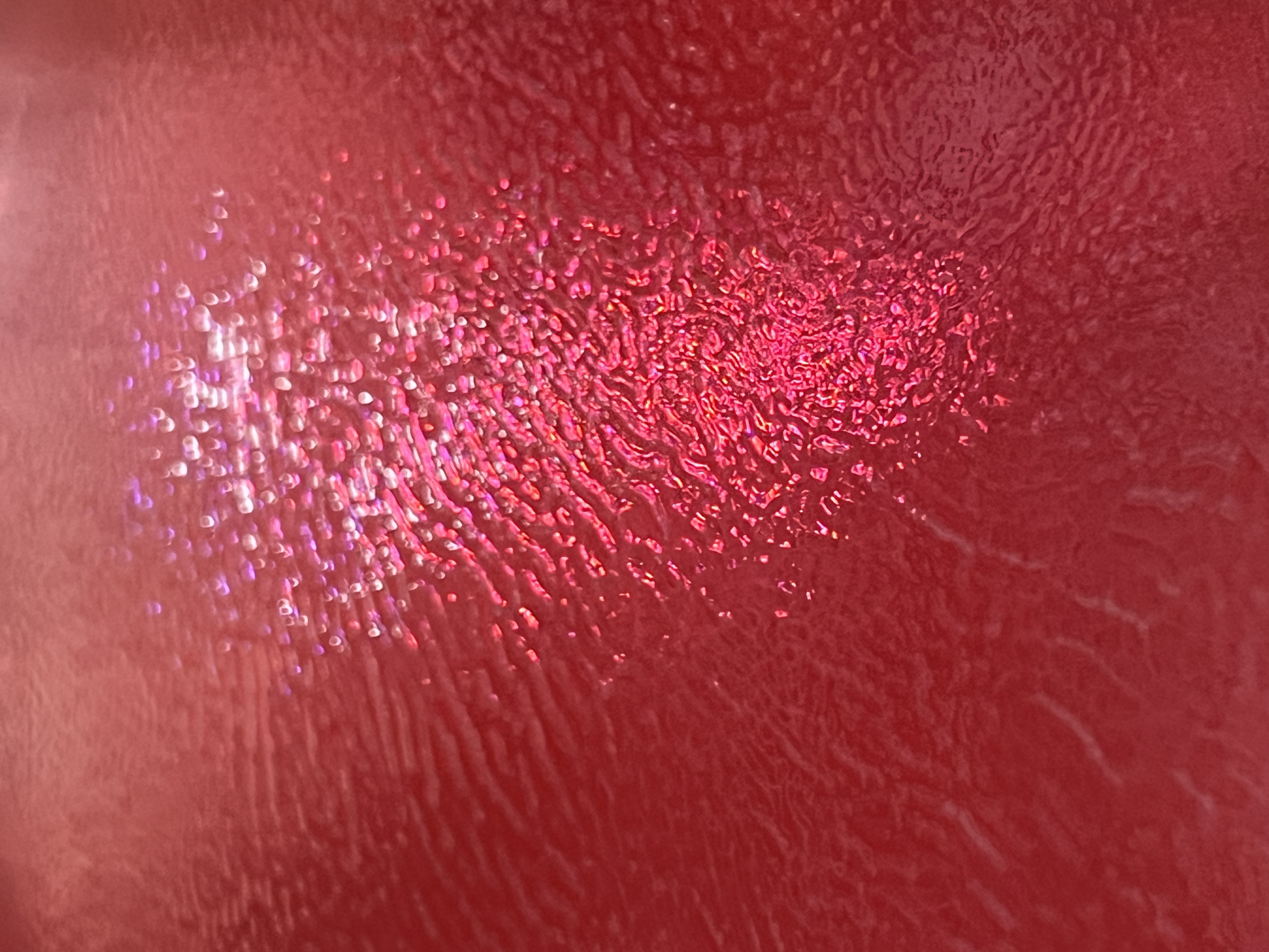
- The beam was uncomfortably close to the holes in the last baffle before the ISS array. It might have been clipped back in March. See ISS_two_hole_baffle.png showing the flash on the right hole. That hole is the "exit" hole for the reflection of the last pico mirror. Left hole is for the incoming beam from the 1" lens (which is right behind the baffle in the picture) but we couldn't take a good photo of the flash in the left hole at the time.
- Once the beam clears the last baffle, the beam is not clipped by the array cover nor the input hole of the array elevator plate.
- IM4 trans beam goes to the first pico mirror cleanly without getting clipped, and it's not clipped at all on the 2" lens.
- IMC trans beam from MC3 hit the IM1 cleanly, clears the baffle after that (IMC_REFL_peri.jpg), and appeared to go to IM2 without getting clipped. Couldn't check IM2->IFI->IM3 but no reason to get suspicious either.
- IM1 transmission was clearly visible using a card and the IR viewer, it was not clipped by the suspension cage with considerable marging and was hitting the steering mirror behind IM1.
- IMC REFL comes out of the last (second) IMC REFL periscope cleanly, the beam is well centered on the baffle hole. See IMC_trans_after_IM1.mp4.
We proceeded to swap the ISS array unit.
- Rahul went inside HAM2 and disconnected the QPD and array PDs after powering down the transimpedance amplifiers. Note that ISS QPD TIA shares the chassis with the IM4 trans, so IM4 trans went dark for some time too.
- The old array assy was separated from the ISS array spacer. The latter remained in the chamber, only the top assy was swapped, as was explained in alog 90158.
- The new array assy SN1202965 (S1202965) was put on top of the array spacer. We took time to double check that the bias voltage for QPD comes to the expected pin on the QPD connector before making connection because the connector could be rotated by 90, 180, or 270 degrees and we can ruin some quadrants. Array PD cables were straightforward, it went as planned in alog 90158.
- TIAs were turned on.
At this point we saw flashes on QPDs as well as array PDs right away. INNER as well as OUTER SUM flashes were both about 0.06 (in the old unit it was 0.03 for OUTER but INNER was much smaller).
We started trying to center the QPD using the first pico mirror. Since pico driver is temporary unavailable (IOT2L is moved away) Rahul turned the pico manually while Elena looked at the laptop screen to monitor flashes in the individual segments. We managed an OK job (arrayqpd_centered.jpg) and checked the beam spots again.
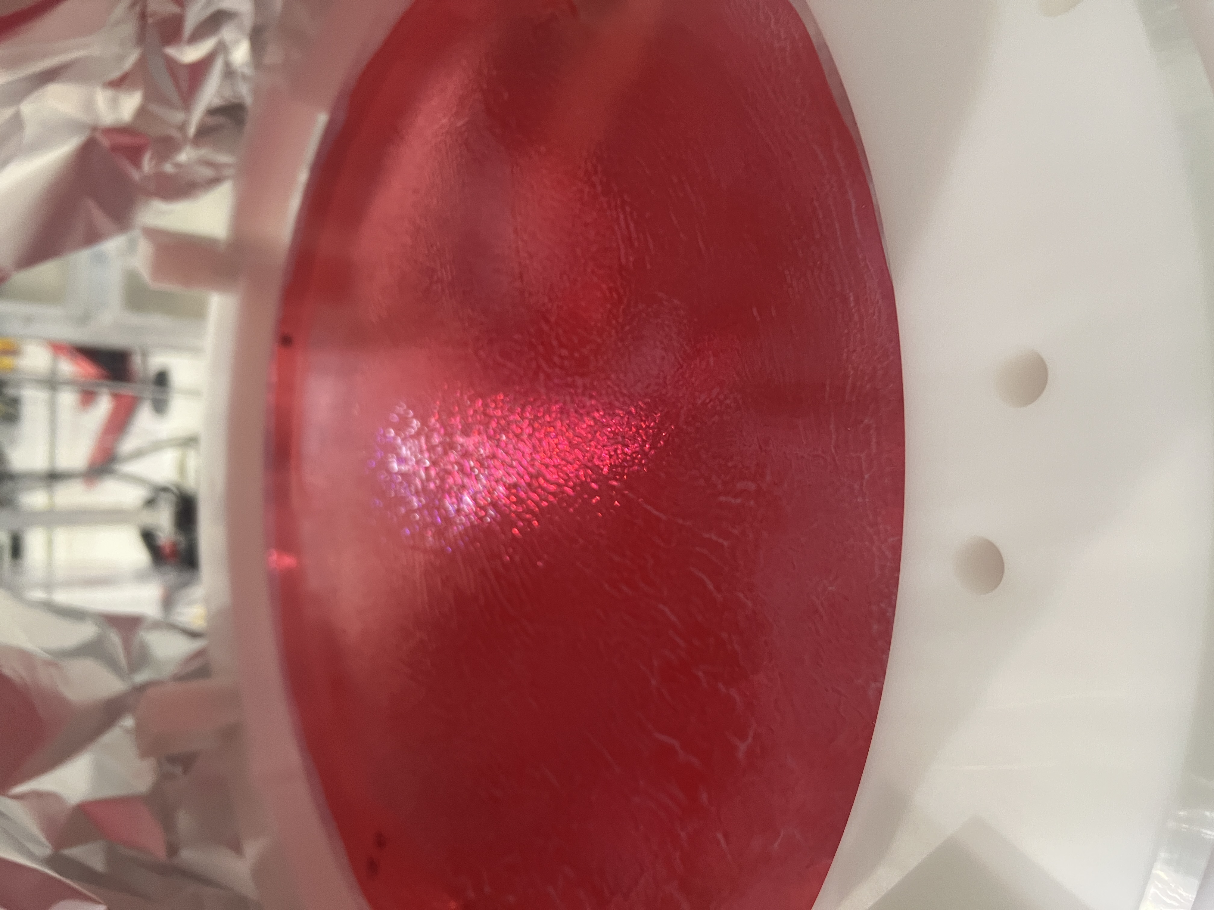
- The beam was very high on the left hole of the two-hole baffle (Rahul has a good pic), high on the right hole (right_hole_after_new_array_QPD_centered.mp4), and OK on the input hold of the array (array_input_after_new_array_QPD_centered.mp4).
The baffle height might not be the same as the lens height and/or the ISS array input hole height, but otherwise it seems that we're shooting down the beam from the 1" lens to the ISS array. We'll check if the lens, baffle and the array are all at the same height or not, and decide how to proceed.


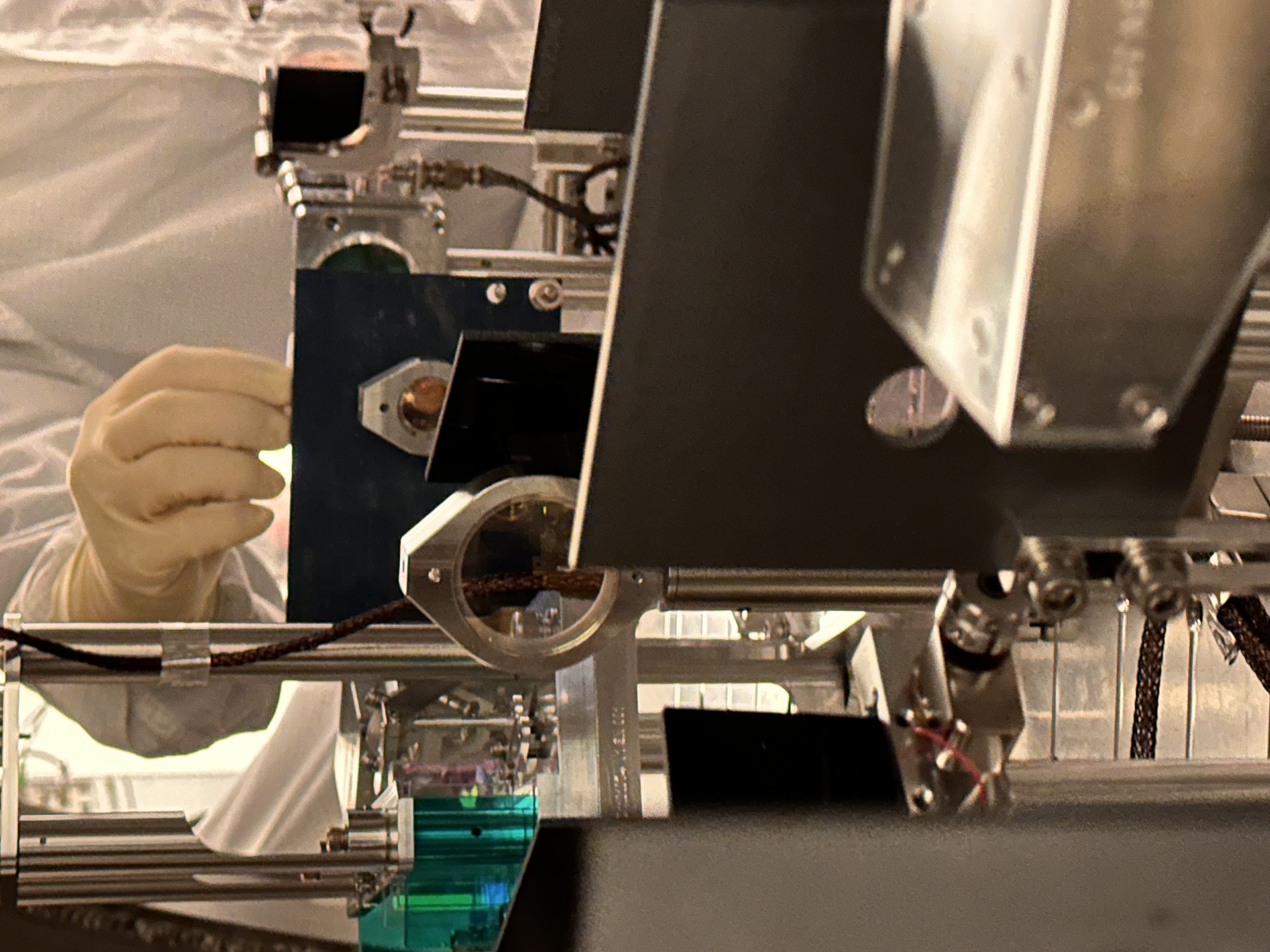
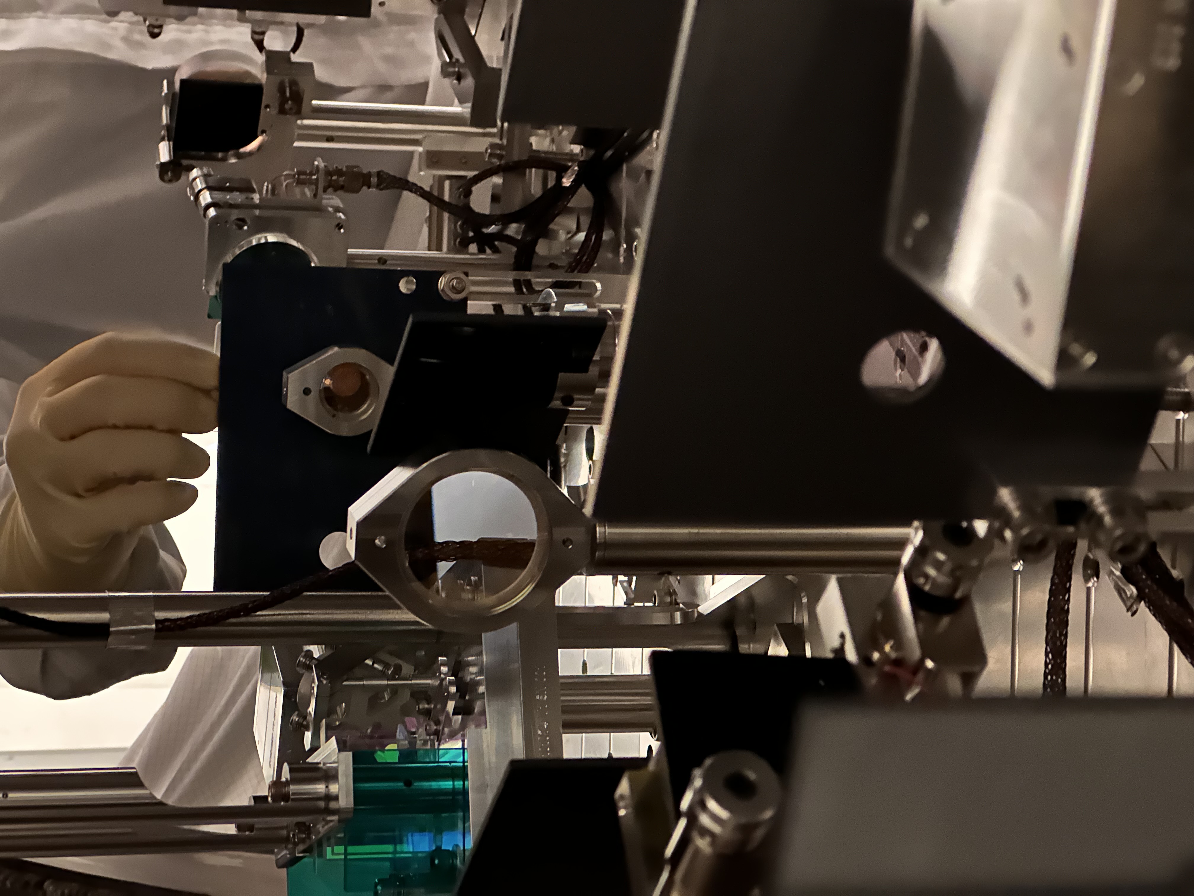
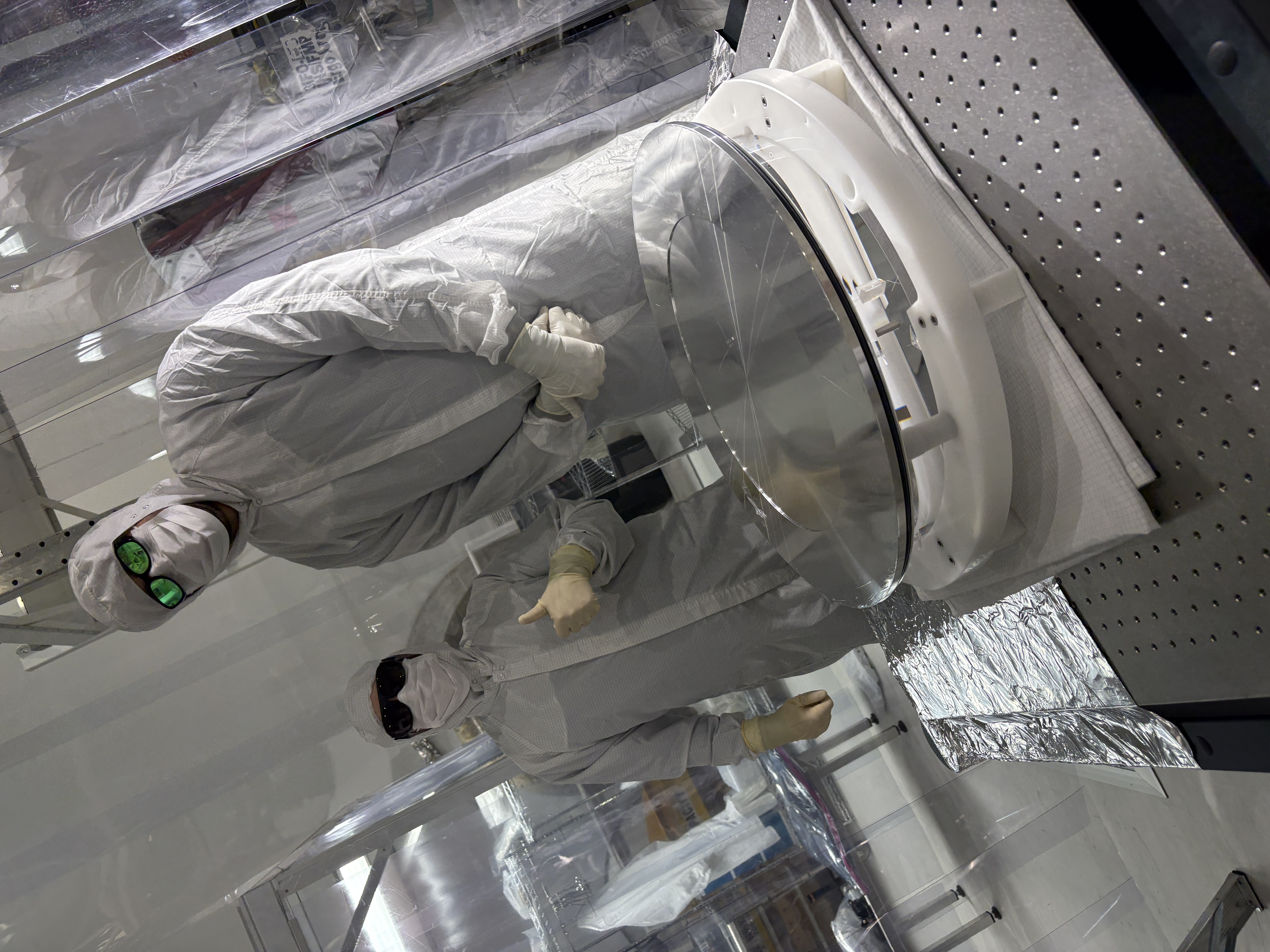
1st: Rahul is disconnecting the QPD cable.
2nd, 3rd (photo by Betsy): Rahul in chamber (me outside).
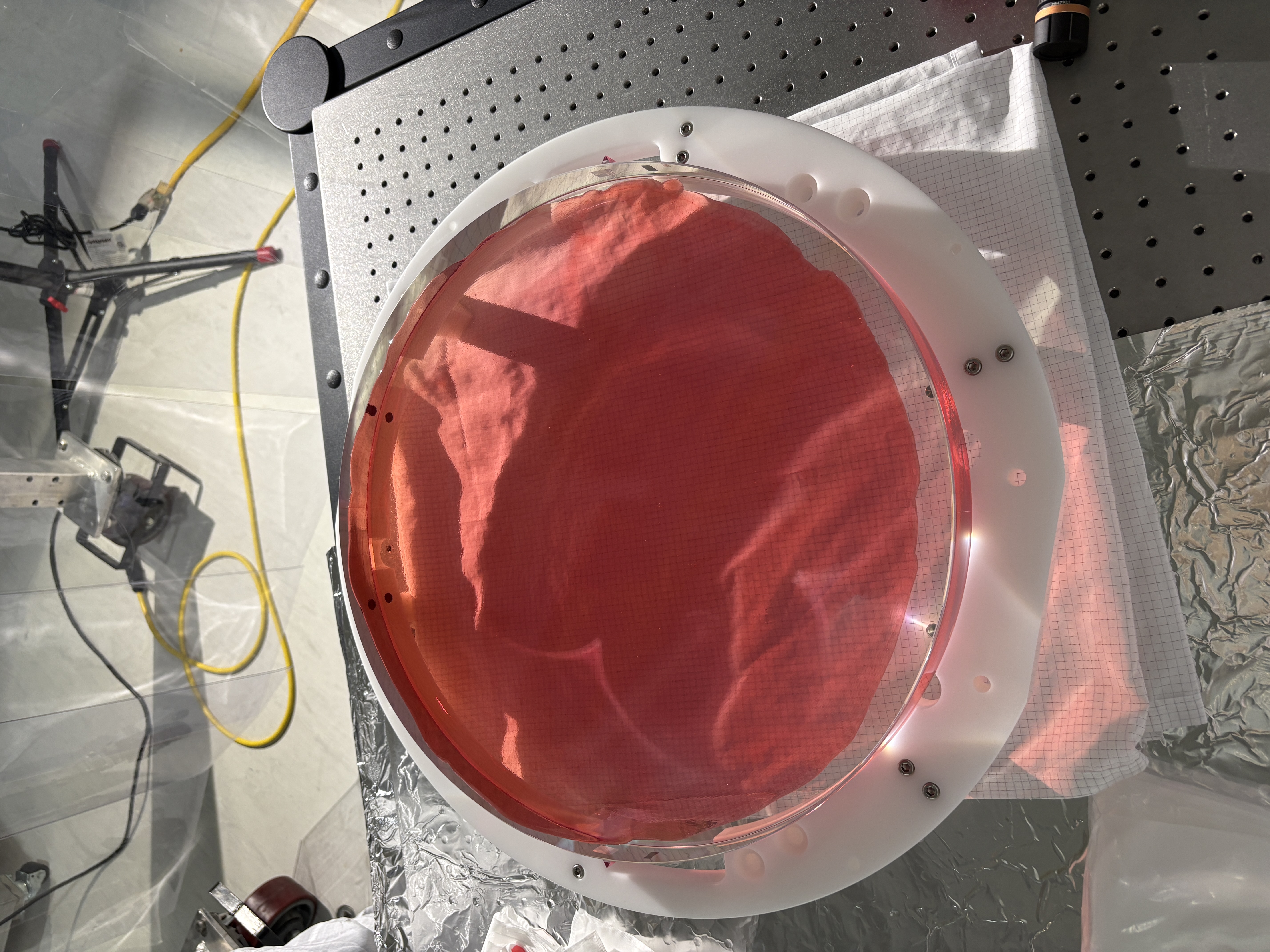
4th: Old unit was extracted. This is S1202971.
5th: New unit (S1202965) to the left, old one to the right.
6th: Rahul after successfully connecting up the new unit in chamber.
7th (photo by Betsy): Elenna (front) is checking the QPD centering, Rahul (a shadow in the back in this photo) is manually moving the pico mirror from -Y door, and I'm somewhere inbetween just observing the two doing a good job.


epo tagging for photos!
Attaching two pictures in reference to Keita's comment above - "The beam was very high on the left hole of the two-hole baffle (Rahul has a good pic), high on the right hole (right_hole_after_new_array_QPD_centered.mp4)"
We concluded that the height of the baffle and the array unit are both correct, the beam is really too high on the 1" lens and we're shooting down from there to the QPD. (This should have been the case for a long time with the old unit. Right after the new unit was installed the beam was on QPD and the beam stayed on the QPD, the diameter of the QPD is 3mm, i.e. we haven't made any huge change on the height of the beam at the left baffle hole.)
- Rahul found in solidworks that the design beam height for LHO is 6.132"=155.75mm.
- Looking at the pictures we took in the chamber, the center height of the two-hole baffle is about 156mm so that's fine.
- The height of the spacer we have, which is supposed to be D1101074 specifically made for LHO, has 4.94"~125.5mm nominal height and our measurement shows somewhat larger than 125.5mm, excellent agreement. We didn't measure the thickness of the thin part of the array base plate (https://dcc.ligo.org/LIGO-D1300323, detailed dimensions are only available in solidworks) nor the distance from the bottom to the beam center of the elevator plate D1400140 (again only available in solidoworks) but Rahul's number makes sense, the height of the actual array unit seems to be according to the design.
With this information, what we'll do next is to gradually bring down the height of the beam on the left baffle hole using the first pico mirror, and use the second pico mirror to bring the beam back on the QPD, until the beam line into the array becomes level-ish with the ISI surface. It doesn't have to be perfect but we don't want to be this much tilted.


