jeffrey.kissel@LIGO.ORG - posted 14:49, Monday 03 April 2017 (35295)
ISC LOCK Guardian Prep for new state: NLN_CAL_MEAS
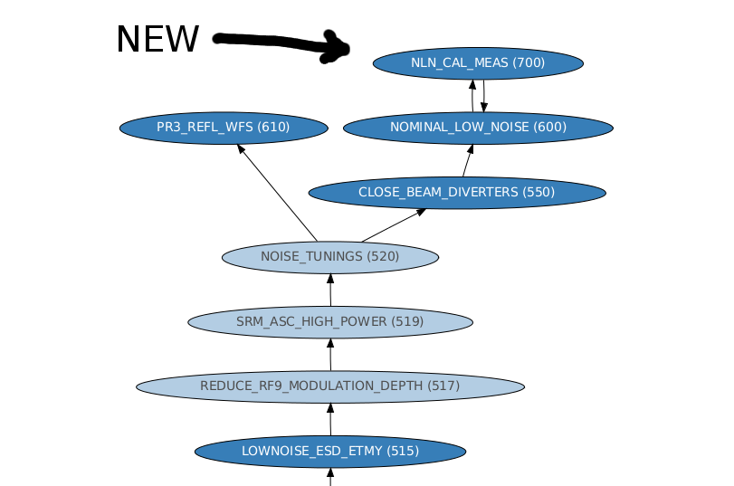
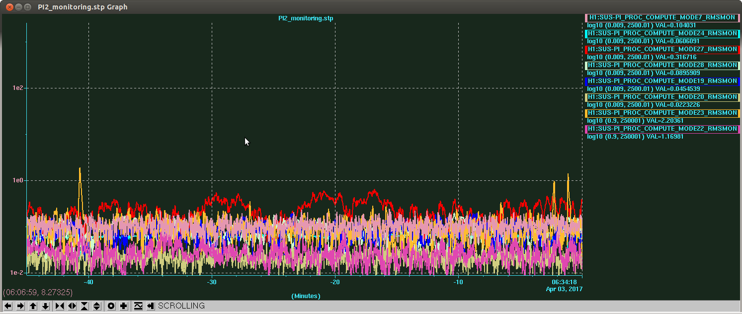
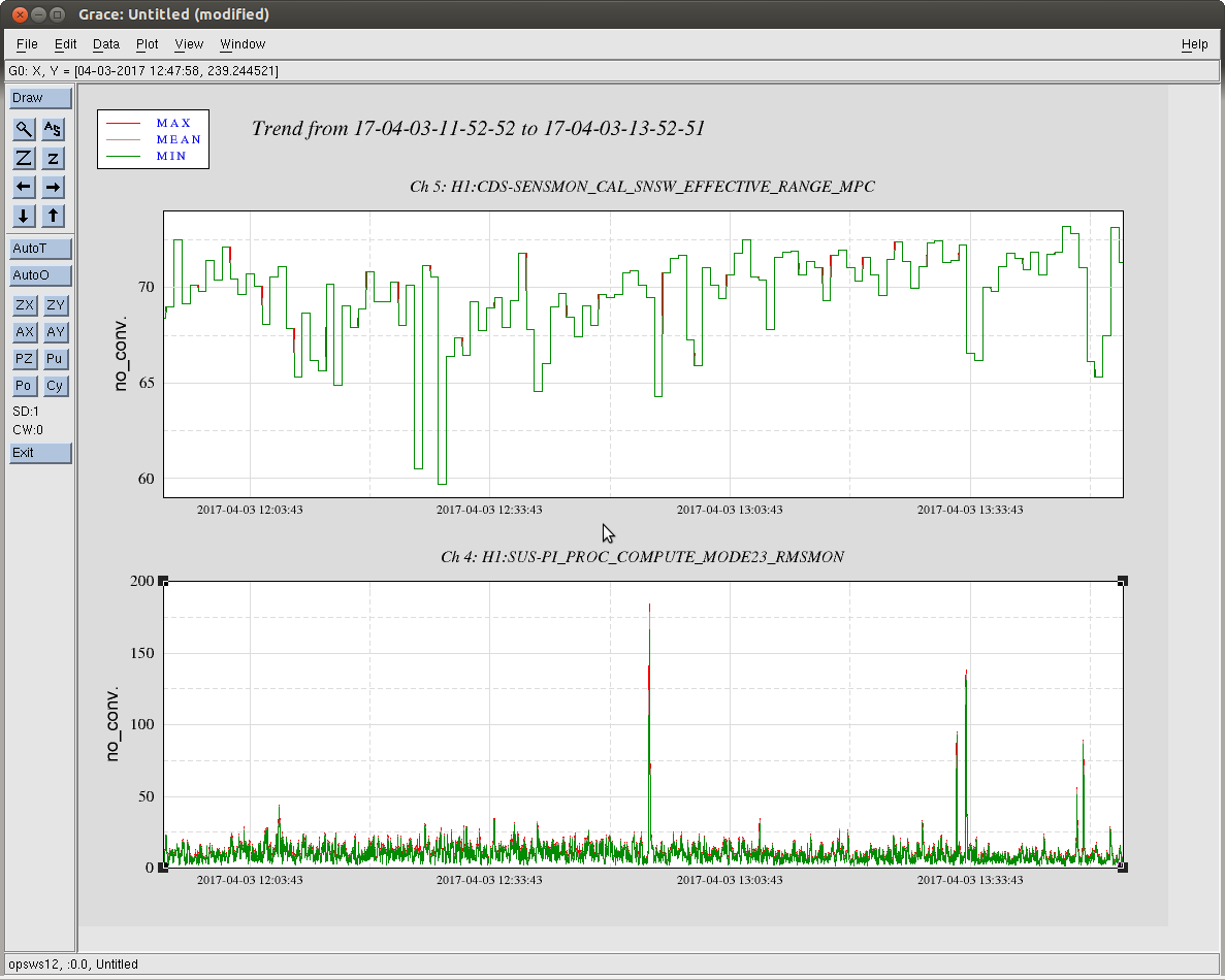
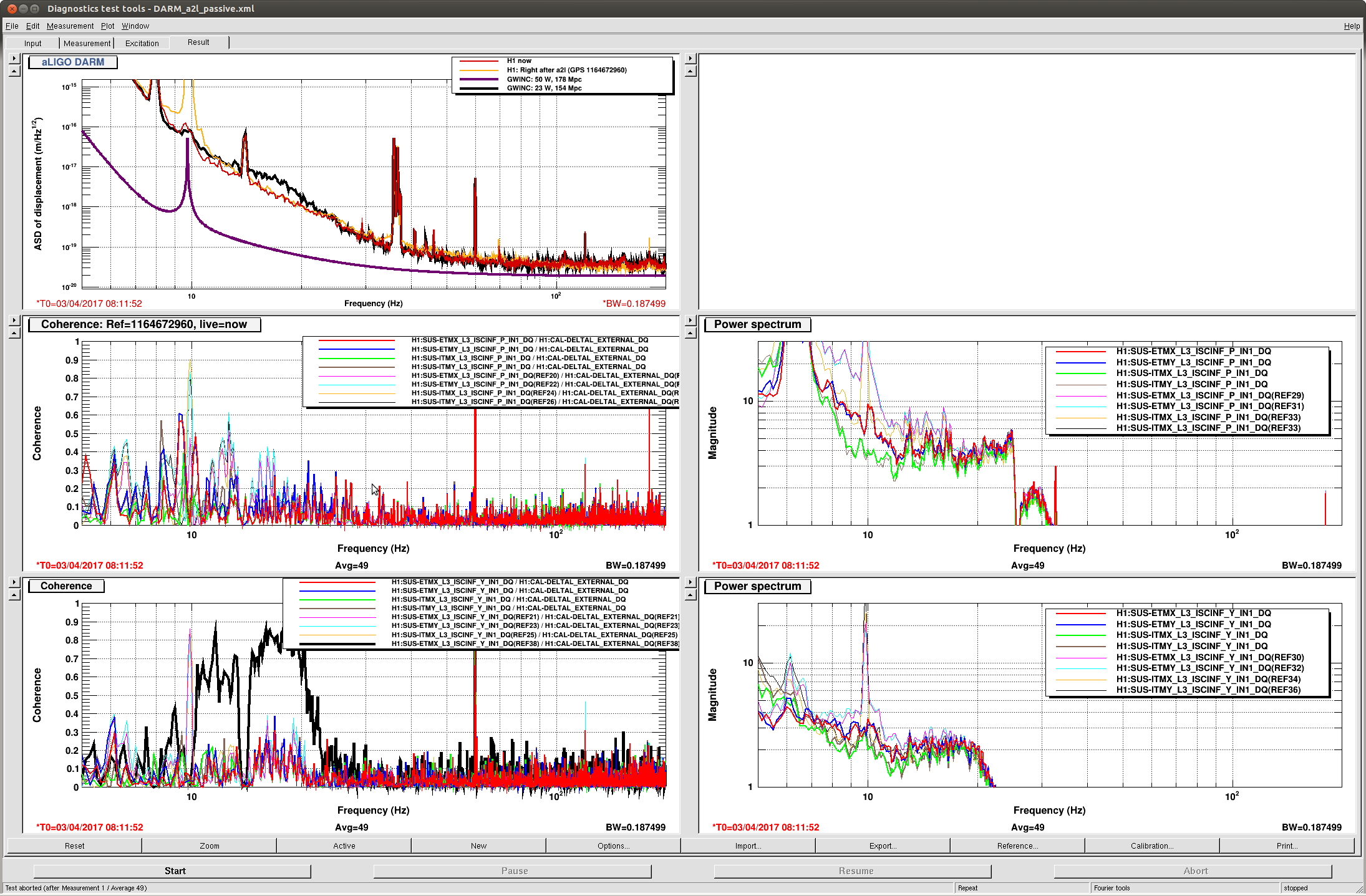
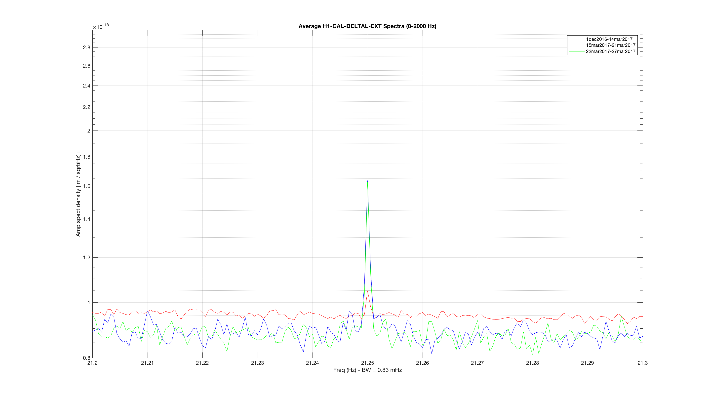
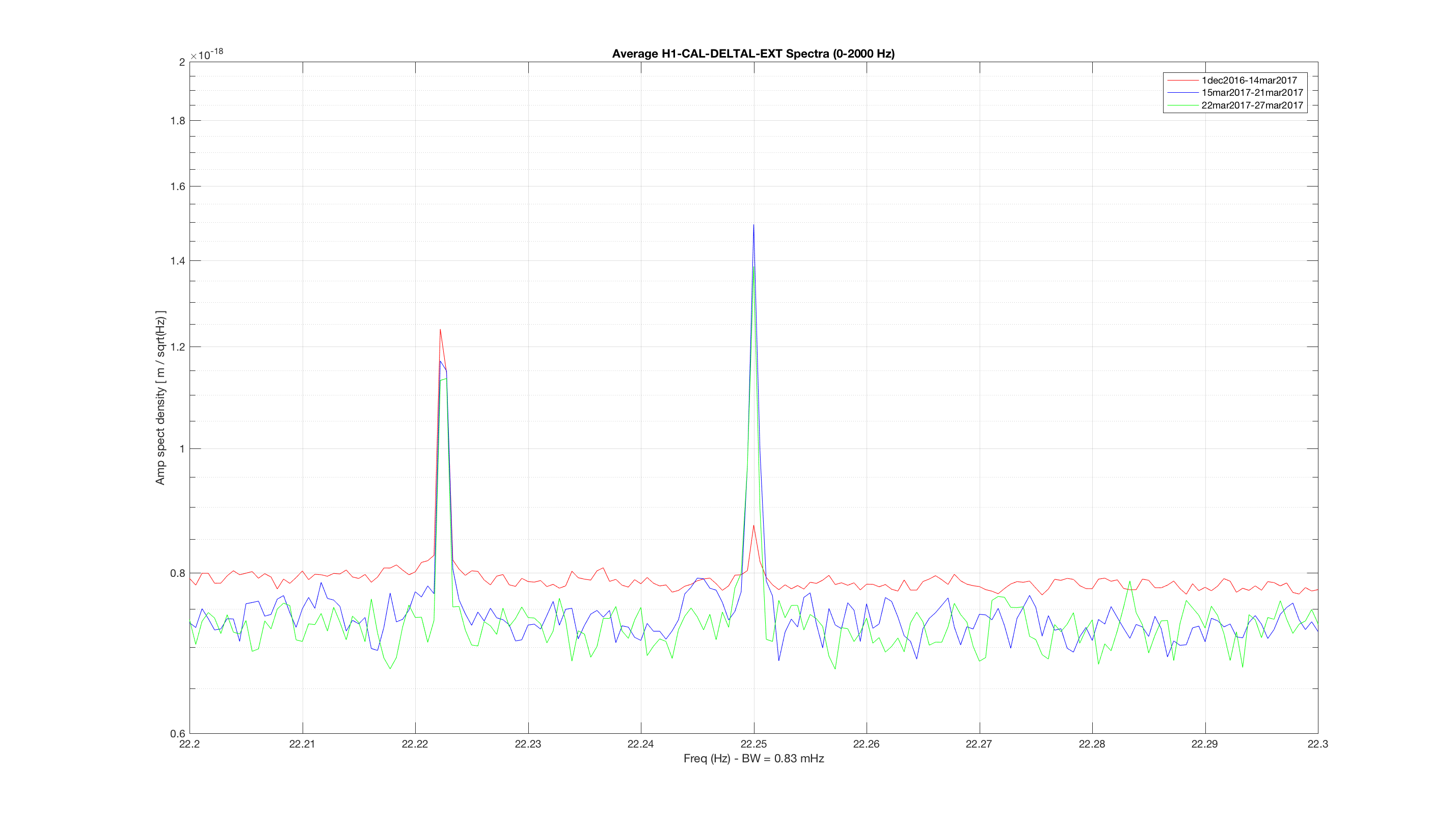
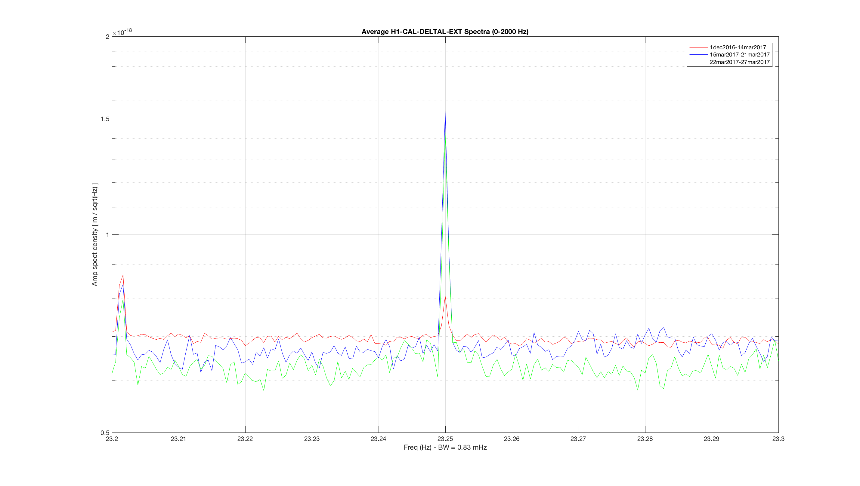
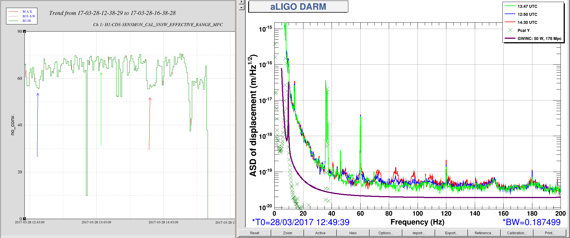
J. Kissel
WP #6557

In order facilitate regular, bi-weekly, CAL measurements, I've added a new state to the ISC_LOCK guardian code called "NLN_CAL_MEAS." So far, the state only turns OFF all calibration lines, as is needed for the frequency dependent sweeps. Upon request to return to NOMINAL_LOW_NOISE, it turns the calibration lines back on, and clears the history in the calculations for front-end calculated time-dependent correction factors (which, sadly, will take several minutes given the impulse responses of some low pass filters in the calculation).

I'll install and test the state tomorrow (4/4) after maintenance is complete.
Thus far, I've only
    - checked for a clean svn status before I started,
    - written in the change to the ISC_LOCK guardian,
    - saved it,
    - checked if the graph was OK with the new edges,
    - commented out all new code
    - committed ISC_LOCK to the svn
so if the code, for whatever reason, gets loaded before tomorrow, there will be no change applied.

I attach the test of the new edges and the representative graph to show how this state fits in the bigger picture.
Images attached to this report