patrick.thomas@LIGO.ORG - posted 04:01, Thursday 30 March 2017 (35211)
Ops Owl Mid Shift Summary
Have remained in observing except to run a2l after LLO lost lock. No issues to report.
Have remained in observing except to run a2l after LLO lost lock. No issues to report.
TITLE: 03/30 Owl Shift: 07:00-15:00 UTC (00:00-08:00 PST), all times posted in UTC
STATE of H1: Observing at 65Mpc
OUTGOING OPERATOR: Nutsinee
CURRENT ENVIRONMENT:
    Wind: 7mph Gusts, 6mph 5min avg
    Primary useism: 0.02 μm/s
    Secondary useism: 0.25 μm/s
QUICK SUMMARY:

No issues to report.
FAMIS #6891

H1:ISI-ITMX_ST1_CPSINF_V1_IN1_DQ is definitely elevated.
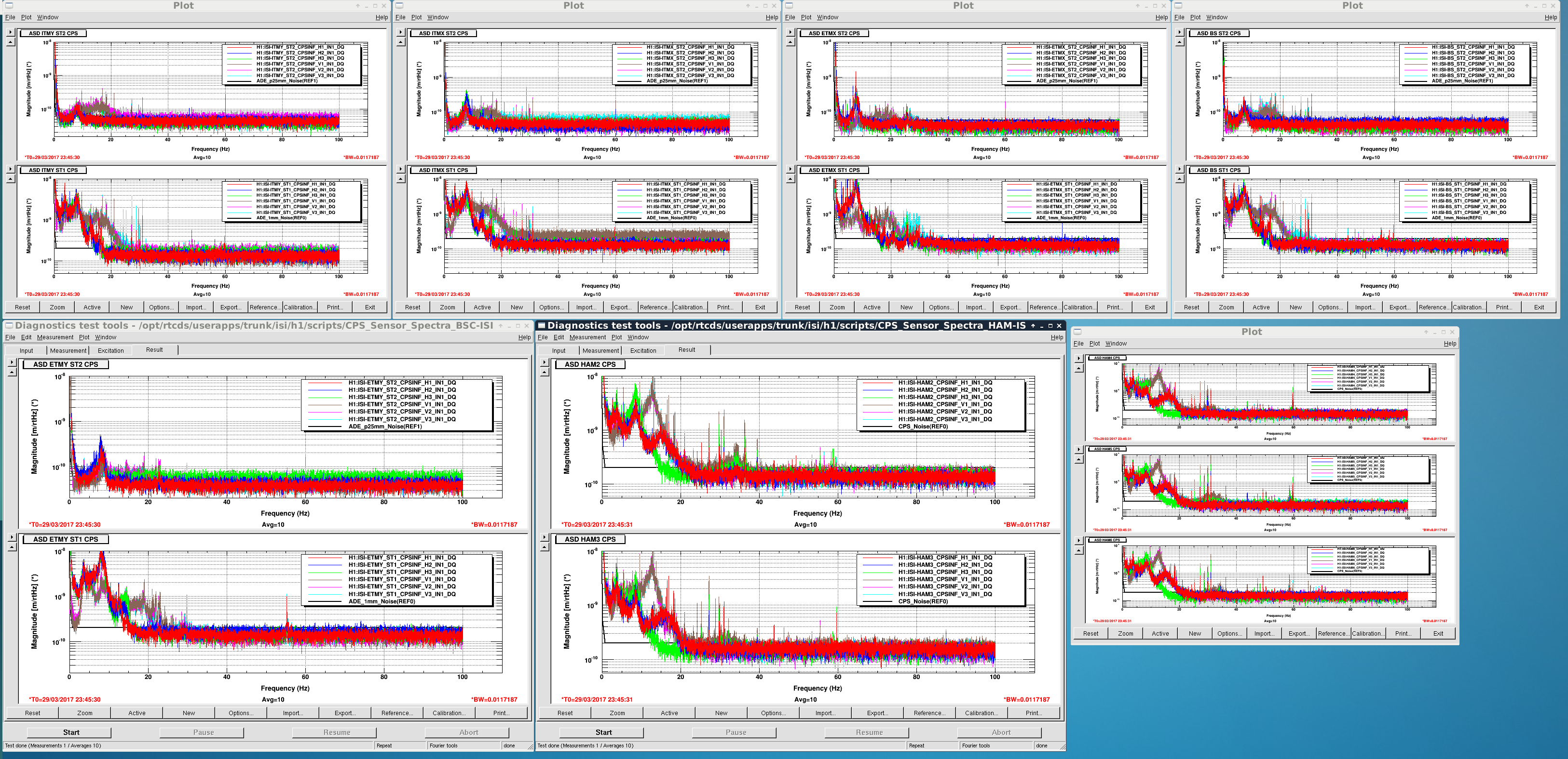
Thanks Patrick. Yes, this is elevated. It isn't extreme but it is certainly not like the others. Better we catch it here than wait for it to get bad and be noisy in band. We'll start with a gauge board un seat/reseat maneuver next opportunity.
FRS 7763.
Nutsinee, Kiwamu (on email and phone)
INITIAL ALIGNMENT
MICH_DARK_LOCKED had a bit of an issue today. It wouldn't go dark no matter how good the alignment seemed. Kiwamu suggested I added 5 counts offset on MICH1. But I was coming back from SRC_ALIGN so I had 10W while attempted to lock MICH for the last time. It worked. Not sure what fixed it though. That 5 counts offset has been removed as soon as I got pass MICH.
Spent quite some time on SRC_ALIGN. It seems like every time ASC tried to engage it kicked SRM too hard and tripped the WD. Beam looked round and error signals looked fine (fluctuating around 0). Just when I decided to call Kiwamu ASC was able to engage.
LOCK ACQUISITION
OMC was a little shy. Needed to request READY_FOR_HANDOFF twice.
SDFs
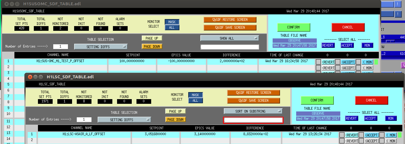
Accepted a couple of SDFs (LSC-ASAIR and SUS_OMC) so I could flip the intent bit. Let us (ops) know if we should revert them back next time we loses lock.These are probably the left overs from PRMI work. See the attachment.
Lockloss 04:23
Stepped out to make coffee. PI rung up when I came back. Couldn't damp it in time.
05:05 UTC Back to Observe
Doing an initial alignment. After some problem with MICH DARK LOCKED (now resolved), SRC ALIGN is not cooperating. SR2 and SRM optics are pretty far off compared to the last time they were locked. This might take some time.
[Cheryl, Daniel, Jenne, Keita, Nutsinee, Kiwamu]
As planned, we locked PRMI with the carrier light resonant. At the very end of the test, we had one good (but short) lock in which the PRC power reached 90% of that for the full interferometer case.
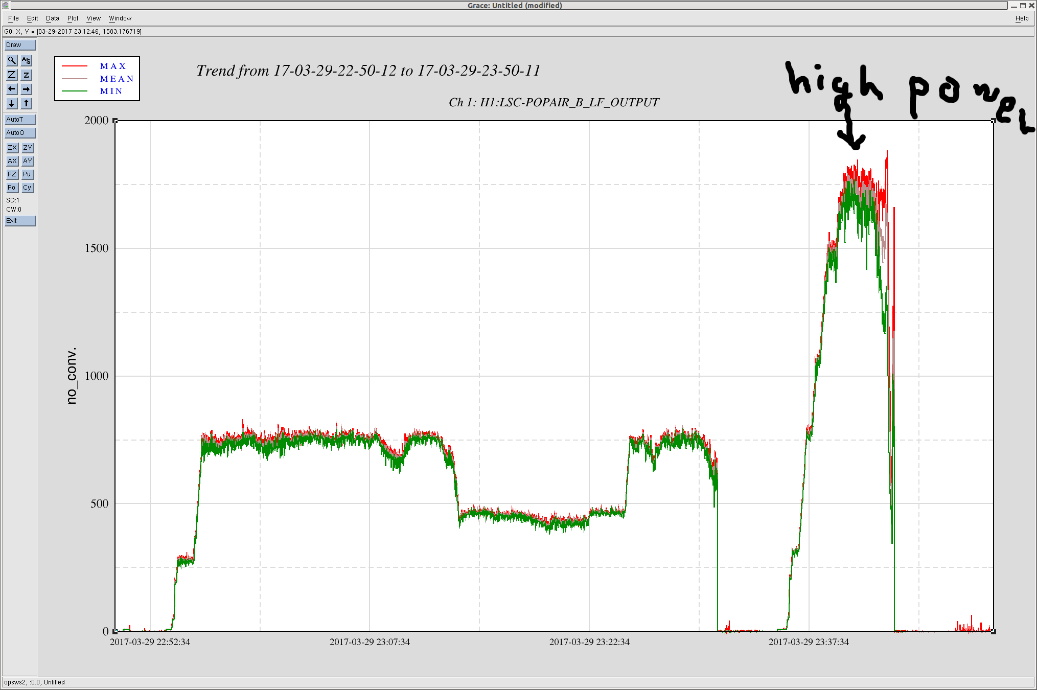
Here is a time line for the last good lock stretch.
See the attached for trend of POP_A_LF. Assuming a power recycling gain of 30 for the full interferometer, we can estimate the usual PRC power to be 30-ish W * 30 = 900 W during O2. Today we achieved 90% of it according to POP_A_LF. Therefore 900 W * 0.9 = 810 W. Considering the 50% splitting ratio at the BS, ITMX receives ~400 W during the last high power test today. In addition, we had a number of lock stretches that lasted longer but with smaller PSL power prior to the last high power test.
Also, technically speaking, MICH wasn't locked at a dark fringe. Instead it was locked at a slightly brighter fringe using the variable finesse technique (35198). Also also, during the last test, Daniel and Keita unplugged a BNC cable from the trigger PD by HAM6 which triggers the fast shutter in HAM6 such that the shutter can stay closed throughout the test to prevent some optics from damaging. After we finished today's test, Daniel put the cable back in so that we can go back to interferometer locking.
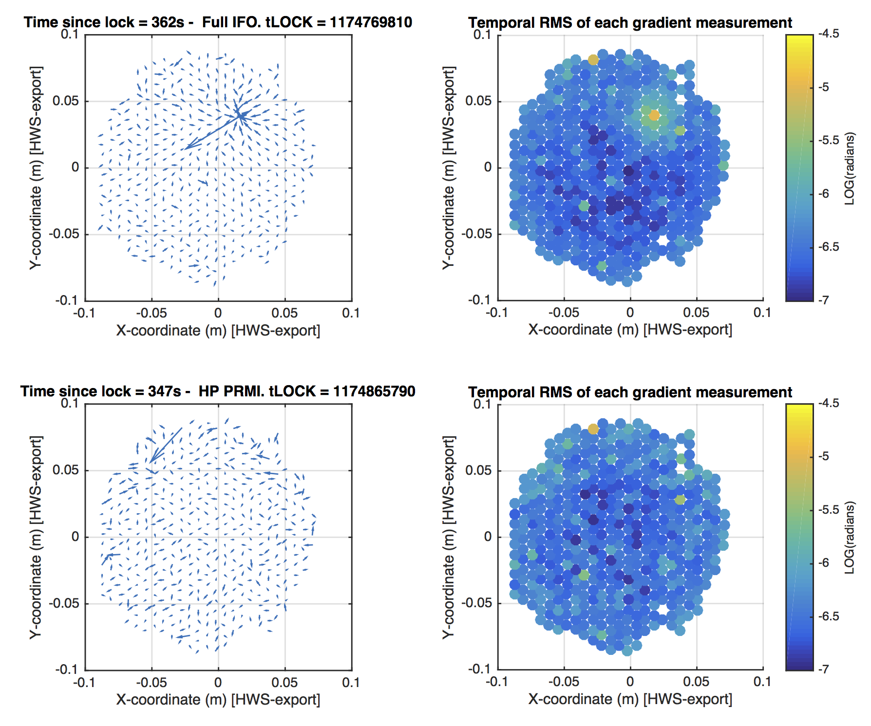
Hartmann sensor test results:
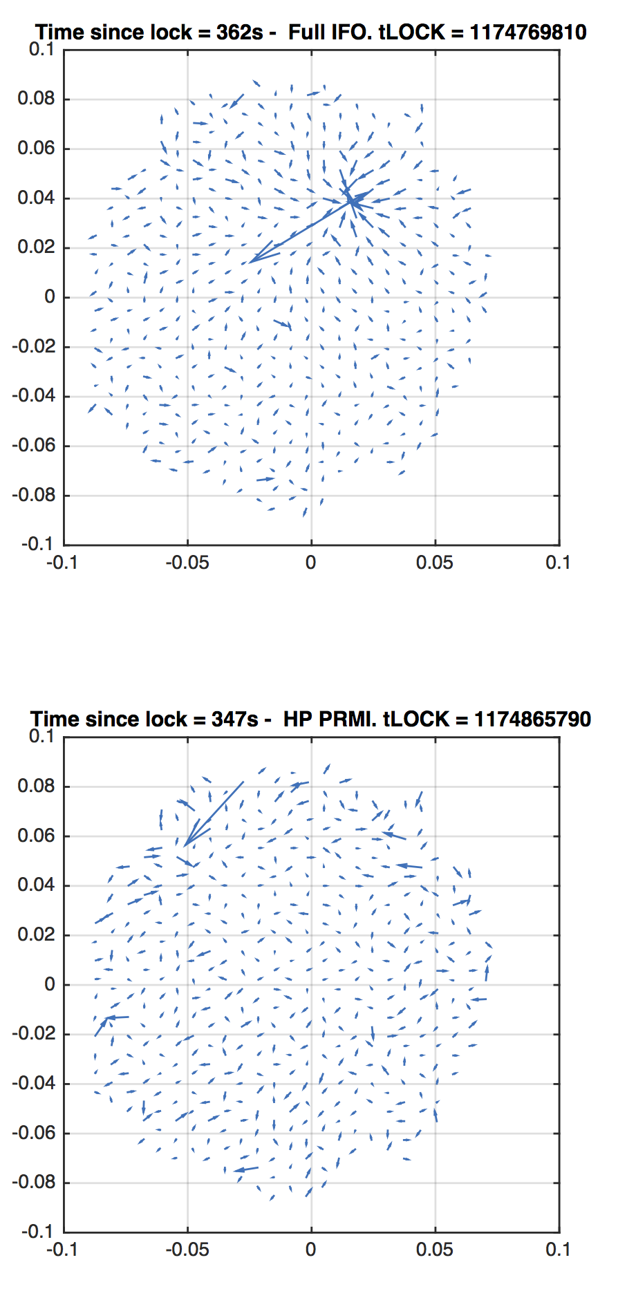
The last lock was initialized at 1174865790, reached full power approximately 210s afterwards and then was lost around 1174866190.
I've plotted the gradient field data for the PRMI test, 350s after locking (cleaning up errant spots). For reference, I've also plotted the gradient field data for the full IFO, 360s after locking. The arrows in both cases are scaled such that they represent almost exactly the same length gradients in the two plots.
The bottom line: the full IFO shows the thermal lens. The high power PRMI does not.
Here's a GIF animation from the time segment for your amusement. There's so little data point that the animation has to be slowed down a bit. The last 120s was some optic misalignment leading to the lockloss.
I'm adding the following plot to show the uncertainty in each of the individual measurements in the HWS gradient field. This should help guide your eye as to which data points are noisy relative to their neighbours. In other words, here is the spatial sensitivity of the Hartmann sensor. This is in the raw exported coordinate system of the Hartmann sensor (that is, scaled to the ITM size but not oriented and not centered).
For example, notice that the point around [-0.03, 0.08] is unusually noisy. So the large arrow associated with it is not signal but noise.
For each data point, the RMS in the gradient of that data point is determined for the 600-1000s of data that is available. That is, for each data point:
U_i = d(WF)/dx, V_i = d(WF)/dy, where i is the i-th measurement of that data point.
RMS = SQRT(VAR(U) + VAR(V))
Note that RMS of the gradient data near the thermal lens is larger because of the presence of signal, not noise.
[Kiwamu, Jenne]
How to lock the PRMI-only
If unlock, do the following (quickly if possible, to reduce the amount of time we're saturating the optics):
Note to self for the future: We weren't ever able to switch to an RF signal for MICH, and so were not able to lock on the true dark fringe. Since we were able to increase the PSL injected power enough to have enough power in the PRC for this test, and we were running low on time, we did not persue this.
Also, PR3 and BS needed to be hand-adjusted in pitch to keep their oplev signals constant as we reduced the MICH offset, and especially after we further increased the power. Rather than commissioning an ASC setup for this one-day test, we just had 2 human in the loop "servos".
TITLE: 03/29 Day Shift: 15:00-23:00 UTC (08:00-16:00 PST), all times posted in UTC
STATE of H1: Commissioning
INCOMING OPERATOR: Nutsinee
SHIFT SUMMARY:
IFO has been down for Commissioning all day in search of some un-wantedness on an ITM surface.
LOG:
Run BRS Drift Mon check: results are posted below. BRS-X looks good. BRS-Y has been in a downward trend since 02/15/2017. It crossed the lower warning line around 03/22/2017. With the exception of a couple of spikes up to zero, it has been below the warning line since.
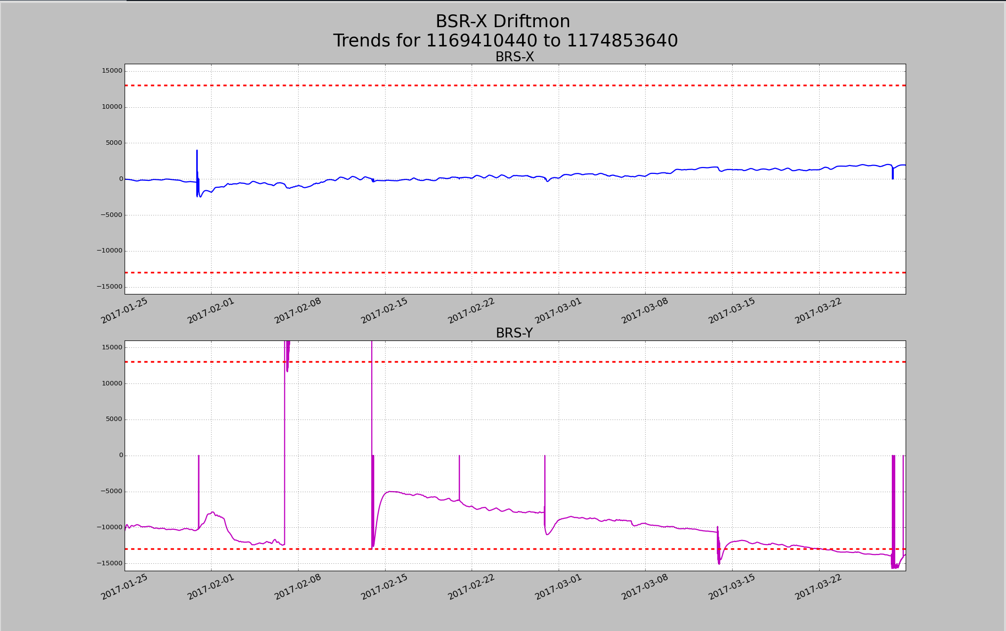
Start of downward trend is 03/15/2017, not 02/15/2017.
Laser Status:
SysStat is good
Front End Power is 34.09W (should be around 30 W)
HPO Output Power is 165.3W
Front End Watch is GREEN
HPO Watch is GREEN
PMC:
It has been locked 0 days, 6 hr 15 minutes (should be days/weeks)
Reflected power = 16.57Watts
Transmitted power = 60.79Watts
PowerSum = 77.36Watts.
FSS:
It has been locked for 0 days 4 hr and 17 min (should be days/weeks)
TPD[V] = 3.368V (min 0.9V)
ISS:
The diffracted power is around 3.7% (should be 3-5%)
Last saturation event was 0 days 4 hours and 45 minutes ago (should be days/weeks)
Possible Issues:
Xtal Chiller "light" is showing intermittent alarm on Statues Screen. 300ml of water was added
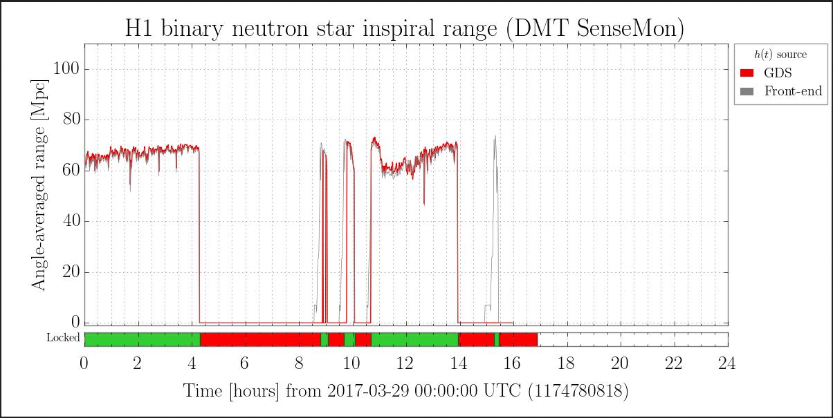
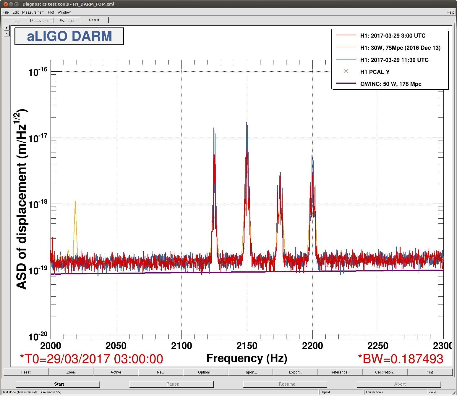
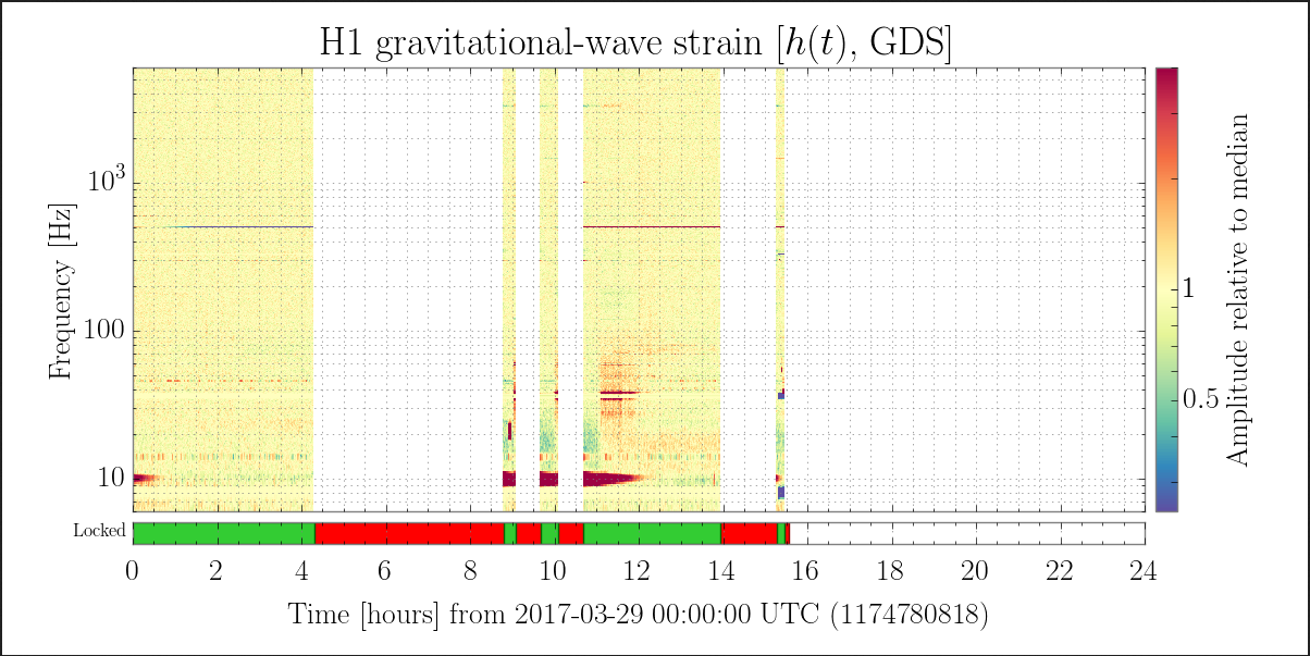
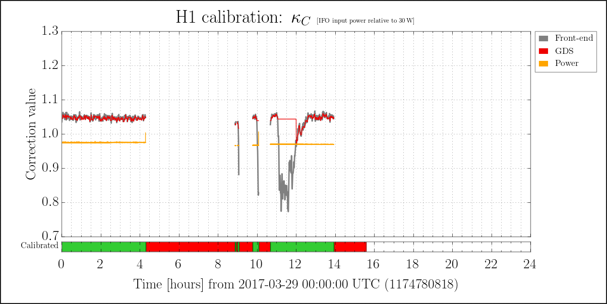
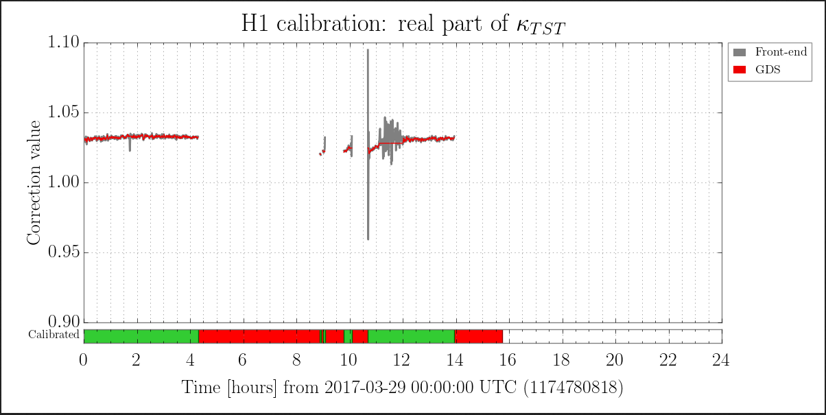
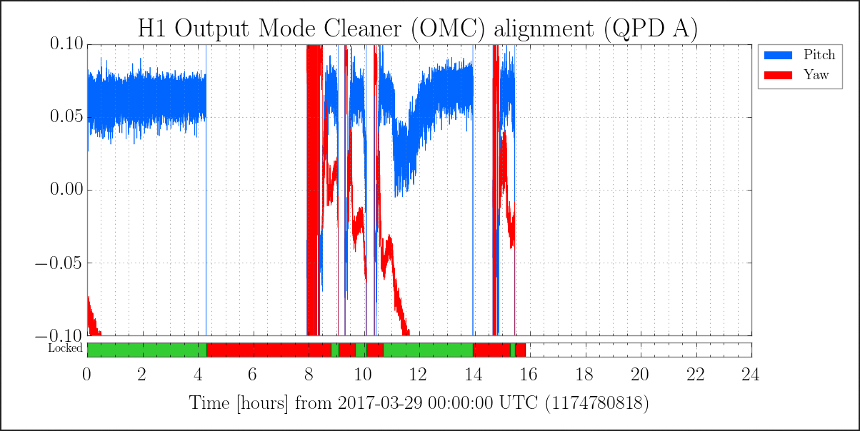
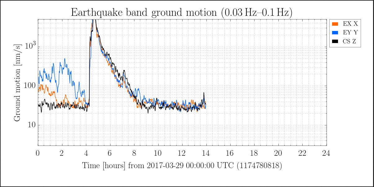
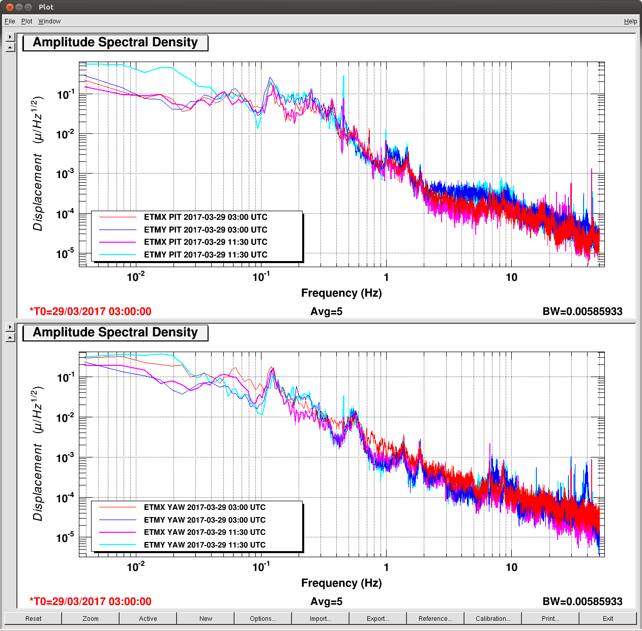
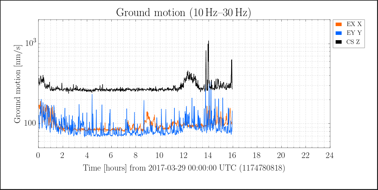
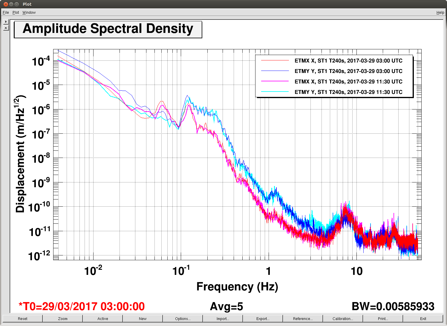
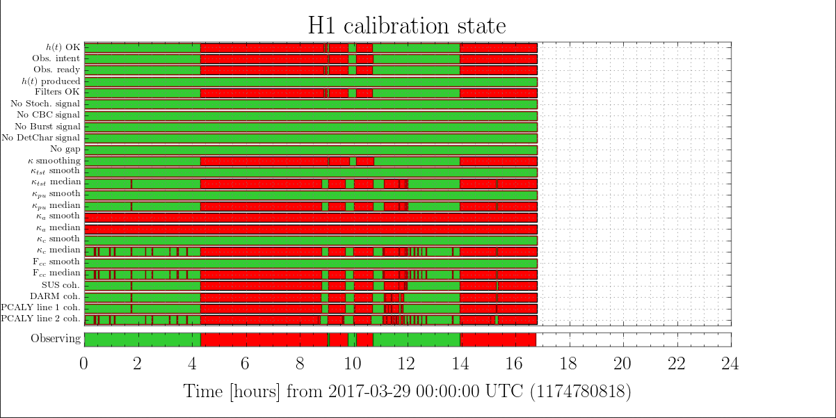
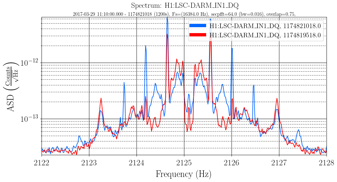
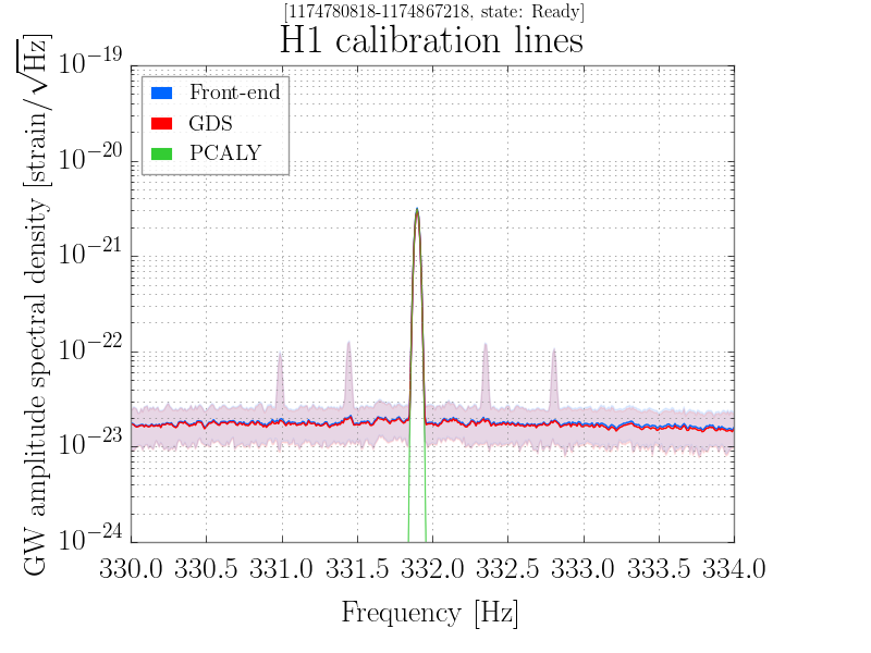
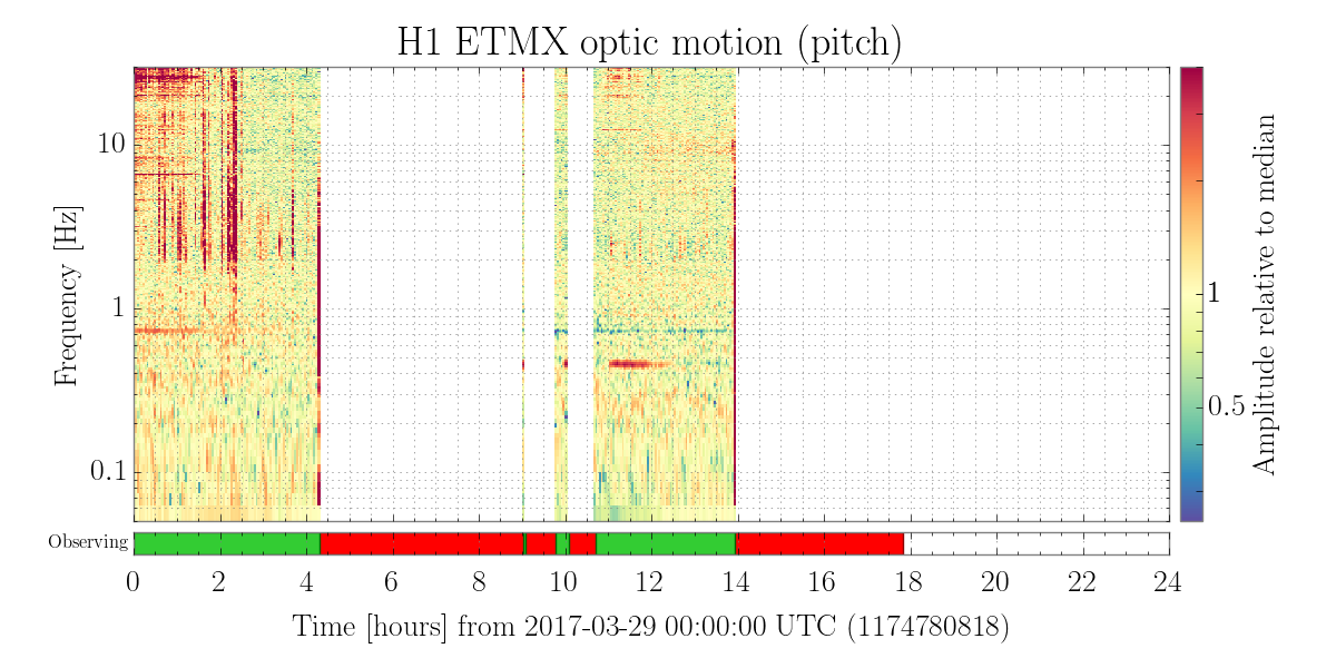
J. Kissel, J. Betzwieser

Patrick had called out that line features the DARM sensitivity around 35 Hz were "broadening and contracting" in a recent lock stretch starting 2017-03-29 11:10 UTC, which impacted the inspiral range (see LHO aLOG 35173). These features are the 35.9, 36.7, 37.3 Hz calibration lines actuated by the ETMY SUS, PCAL, and overall DARM_CTRL, respectively.

What Patrick has seen is classic alignment-related up-conversion, where low-frequency (between 0.05-10 Hz) angular motion mixes with the intentionally, and necessarily loud calibration lines and creates side-bands on the CAL lines that mirror the ASD of angular motion. We've been anecdotally/casually/qaulitatively seeing this several times in the recent past.

This time, however, it seems to have gone so far as to pollute the calculation of the time-dependent correction factors, which are applied to the astrophysical output -- namely the relative ESD/TST stage actuation strength change ("kappa_TST"), and the relative optical gain change ("kappa_C"). Since the data were so noisy around these lines (the SNR dropped from the typical ~500 to less than 10), this dropped the coherence between excitation and DARM, and increased the uncertainty beyond our pre-defined thresholds for good data.

As such I recommend this data stretch to be flagged as garbage by DetChar, from where bits 13 & 15 ("kappa_TST median" and "kappa_PU median") of the H1:GDS-CALIB_STATE_VECTOR are red during this observational stretch.

I attach good deal of plots to help support the interrelated case between
    - The DELTAL_EXT sensitivity of the detector, zoomed in around both the 2150 Hz OMC dither lines and CAL lines
    - OMC Dither Alignment Control (whose error signals are informed by 4, evenly spaced lines between 2125 and 2200 Hz)
    - OMC SUS and OM3 alignment
    - DHARD Pitch Control
    - The noisy kappa_TST and kappa_C
and then other plots that show it's NOT causally related to
    - Earthquakes (the recent EQ at 4:30 UTC was done by then)
    - ETMY Optical Lever Excursions (ETMY's optical lever went off into the weeds, but what's shown in the BLRMS is just the ring-down of the low-pass filter)
    - 1-30 Hz GND Motion (the increase happens *after* this alignment excursion)
    - Large differential motion of the ETMs (ETMX X and ETMY Y show that same ISI ST1 performance at 11:30 UTC and 03:00 UTC which are bad and good times, repectively)

I don't have any speculation as to which of the inter-related symptoms are the actual cause of the problem, and/or I don't have a clue as to why the OMC dither line heights are so much louder during the bad time. I'll ask around for speculation from other members of the commissioning team.
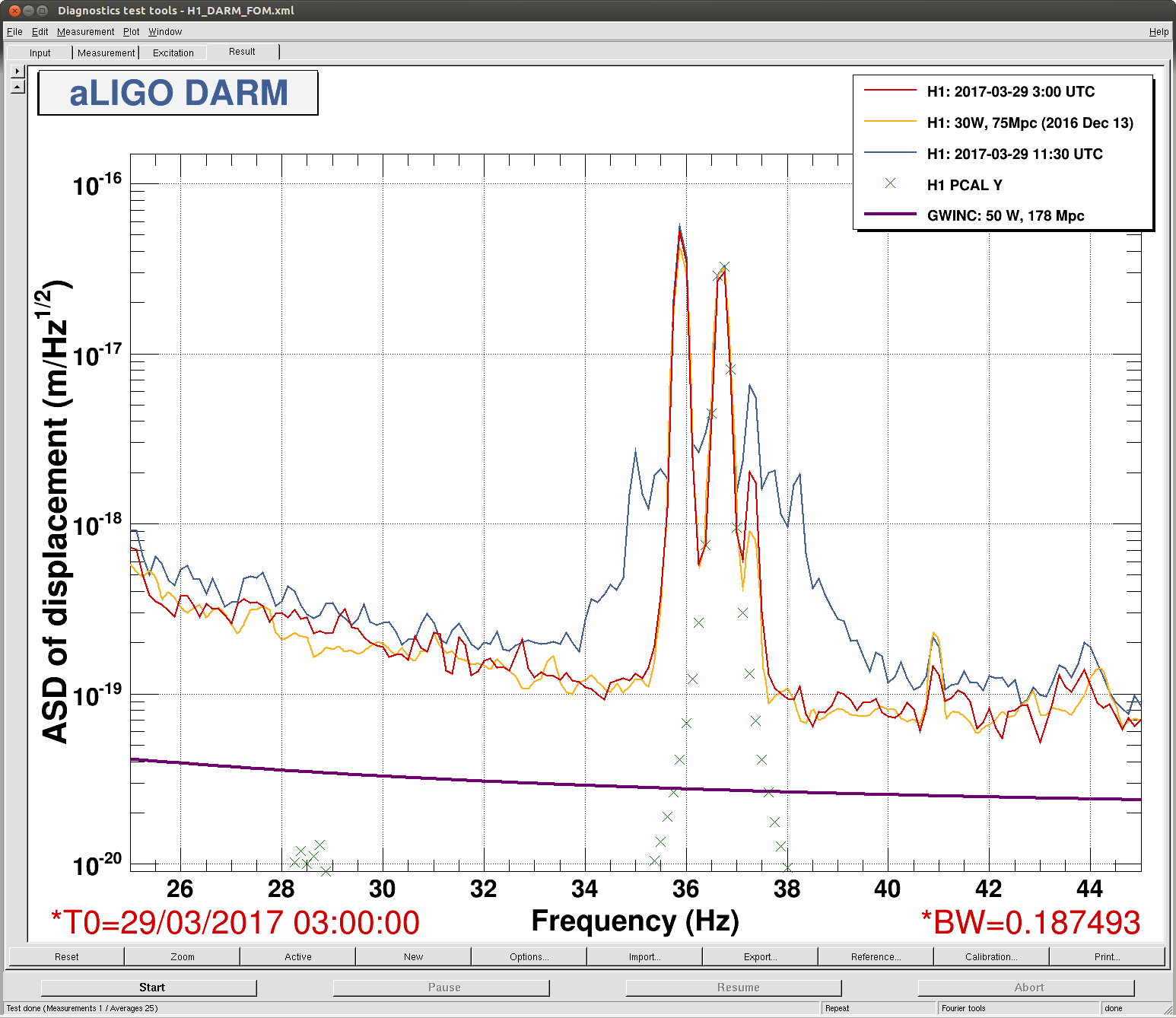
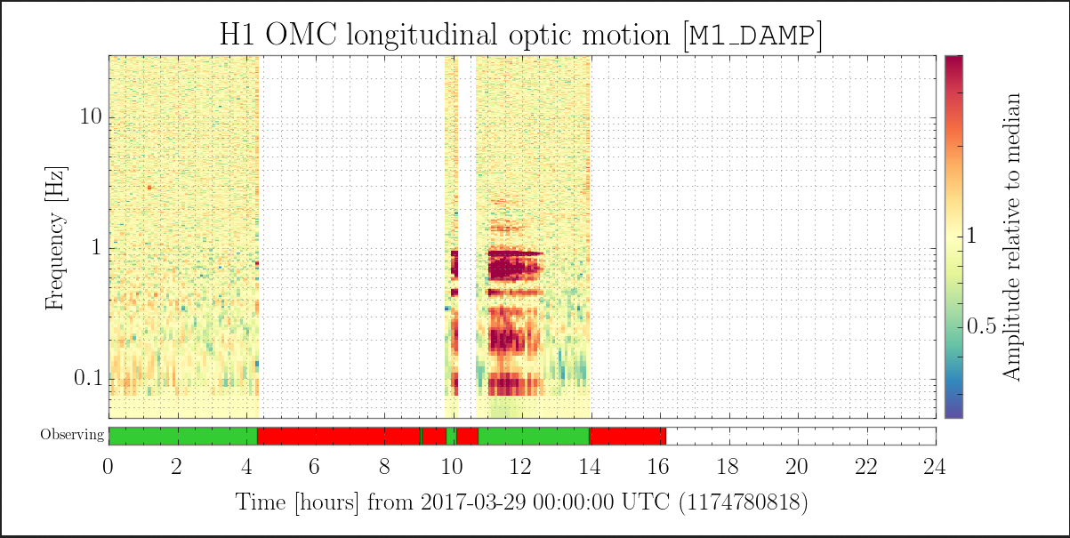
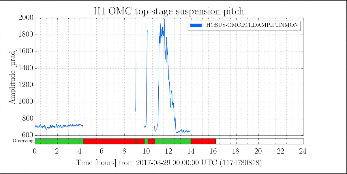
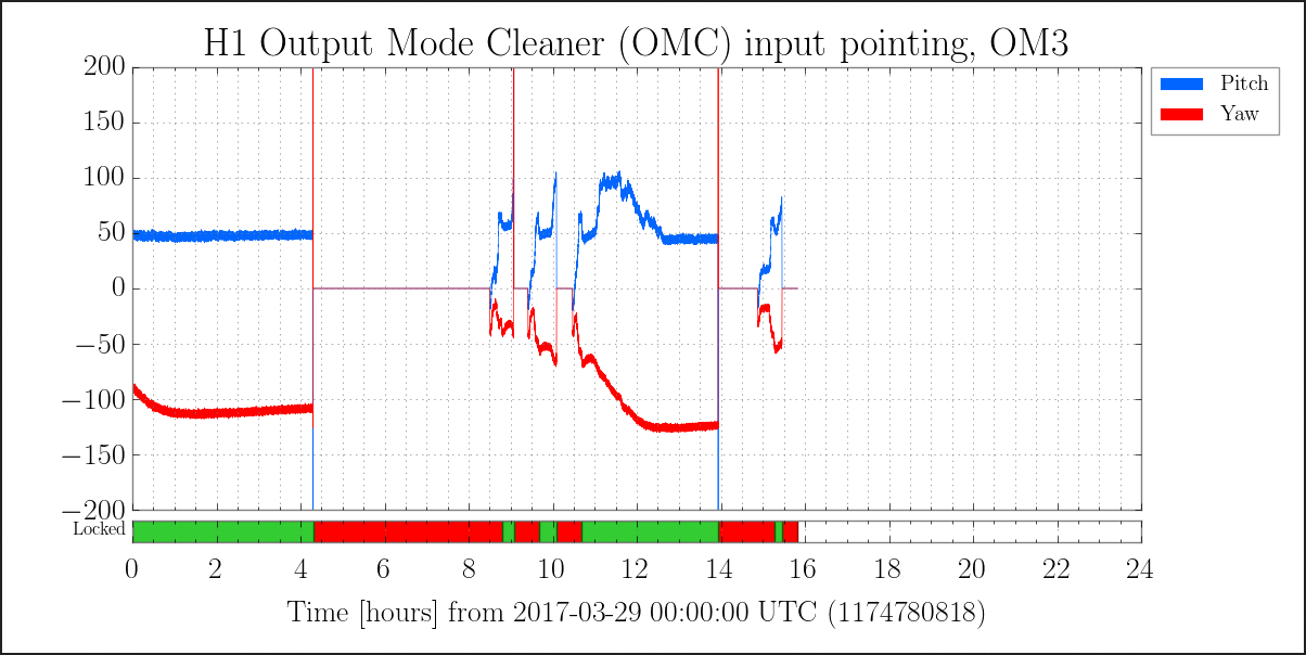
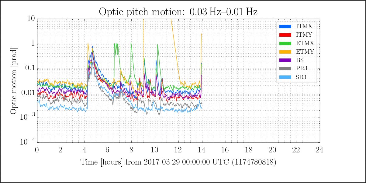
The difference in the calibration lines and the OMC dither heights seems to be mostly an increase in sidebands at about 0.4 Hz.

The first attachment is a zoomed in spectrum of the OMC dither at 2225.1 Hz compared to the time just before the bad time. The dither line itself isn't very visible in DARM (since the alignment should suppress it), the difference in the feature around that frequency are sidebands spaced by about 0.4 Hz. The second attachment is the 331.whatever Hz calibration line, which has similar sidebands. I think the same is true for the three near 30 Hz, but they overlap and it's hard to sort out.

At the same time, the test mass oplevs all show an increase in the 0.43 Hz pitch mode. Attachment three is the ETMX spectrogram. There's an increase in angular motion on other optics, like the OMC, especially at this frequency and its double. But I would guess that they're just following the motion of the test masses.

I'll point out again that the ITMY oplev signal looks very strange (final attachment). Could something wrong with the oplev damping ring up the 0.43 Hz mode?
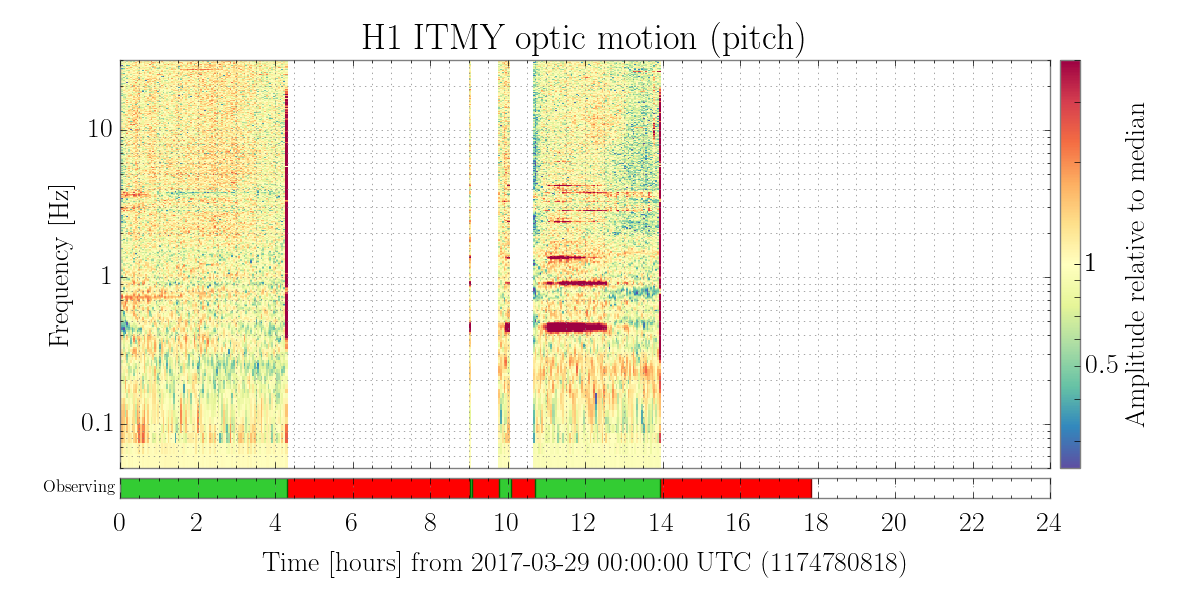
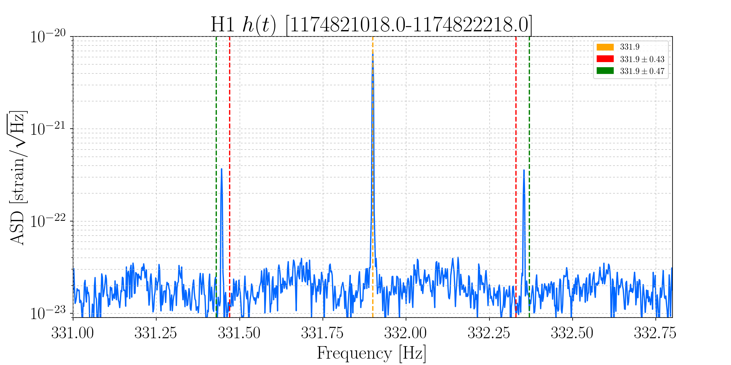
@Andy, DetChar, et. al

I think you may be on to something, but I'm not sure I would call the ITMY optical lever the *cause* just yet per se. Recall that is radiation pressure to ~0.4 Hz pitch mode coupling in the arm cavities of the IFO (G1600864), so the ITM optical lever may just be another witness to the problem (i.e. something goes bad that kicks up the instability and ITMs see it, and the Oplev Damping / ASC / LSC system tries to follow / control it) -- and the signals may look particularly bad (i.e. the harmonics) because the optical lever spot is clipping, or on the edge of the QPD or something. I agree that it's getting worse (this problem is happening more frequently), though.

I say this because -- continuing to browse around the summary pages, I see two other recent examples of this whole inter-related badness that impacts to 35 Hz calibration lines:
    2017-03-24 from ~01:30 - 2:45 UTC
        BNS Range
        DARM Spectrogram
        35 Hz CAL Lines and harmonics
        kappa_C TDCF
        DHARD Control
        OM3 Pointing
        Beam Alignment into the OMC Cavity
        ITMY Pitch via Optical Lever

    2017-03-22 from ~4:45 - 5:00 UTC
        BNS Range
        DARM Spectrogram
        35 Hz CAL Lines and harmonics
        kappa_C TDCF
        DHARD control
        OM3 Pointing
        Beam Alignment into the OMC cavity
        ITMY Pitch via Optical Lever

But I see *tons* of examples of the ITMY bad news that don't seem to have similar effects over the past several months.

(PS it would be *super* awesome if we could create a custom summary page with all of the above graphics / cross-coupled info; it'll save us from concatenating plots from 15 pages and lend it self to better pattern recognition).

The other thing, is that -- at least from what I've found and with what precision I can get on a 24 hr trend from the summary pages (which is not precise at all), the ITMY optical lever problems seem to come and go slowly, where the OMC alignment, CAL line problems, and Range decay all seem to happen a bit more suddenly.

Also -- how fine a resolution spectra are you gathering on this? Can you resolve whether the harmonics you see are 0.43 vs 0.47 Hz? The spectra / spectrograms on the summary pages don't have this kind of precision, and as far as I know, there's no cursor feature on LIGO DV, so I worry that you're colloquially referring to the wrong mode, which may be confusing the study -- especially since these modes move around with Sigg-Siddles radiation pressure stiffening / softening (see, e.g. G1600509).

Did we see any noticeable change after Jason swapped out the ITMY laser on March 7th (see LHO aLOG 34646)? I couldn't find any conclusive correlation between the swap, the above mentioned calibration line shoulder / harmonics, and the badness of ITMY after browsing through the summary pages from Feb 1 to today.
Jeff, as requested, find attached a 2mHz-resolution FFT, with appropriate markings for 0.43 and 0.47 Hz side-bands. It looks like the side-bands are actually 0.454 Hz, if that means anything to anybody.
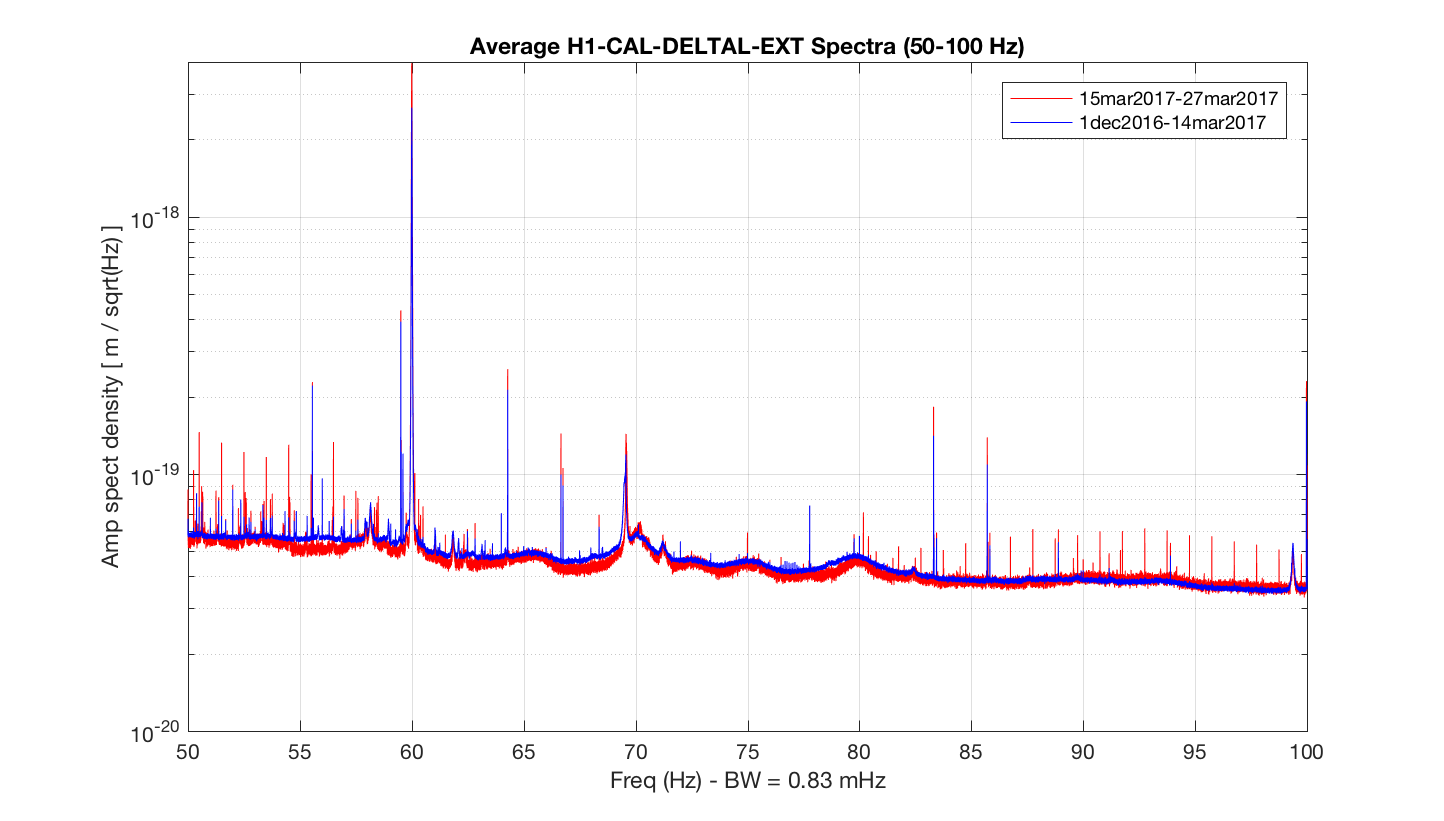
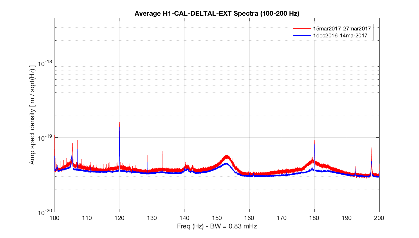
It appears that some maintenance work on Tuesday March 14 led to degradation
with respect to narrow lines in H1 DARM. The attached inverse-noise-weight spectra
compare 1210 hours of data from the start of O2 until early morning of March 14 with
242 hours since that time.

Summary of substantial comb changes:

The comb with 0.9999-Hz spacing nearly aligned with N + 0.25 Hz (N = 15-55) is stronger.

There is a new comb with 0.999984-Hz spacing visible nearly aligned with N + 0.75 Hz (N = 41-71)

There is a new comb with 1.0000-Hz spacing visible at N - 0.0006 Hz (N = 104-125)

Much activity was reported in the alog for March 14, but what jumps out at me
are two references to HWS work: here and here.

Are there HWS cameras running during observing mode?

I had thought those things were verboten in observing mode, given their
propensity to make combs.

Fig 1: 20-50 Hz comparison (before and after March 14 maintenance)
Fig 2: 50-100 Hz (before and after March 14 maintenance)
Fig 3: 100-150 Hz  (before and after March 14 maintenance)

Attachment has full set of comparison sub-bands up to 2000 Hz with both A-B and B-A orderings to make clear which lines are truly new or louder.
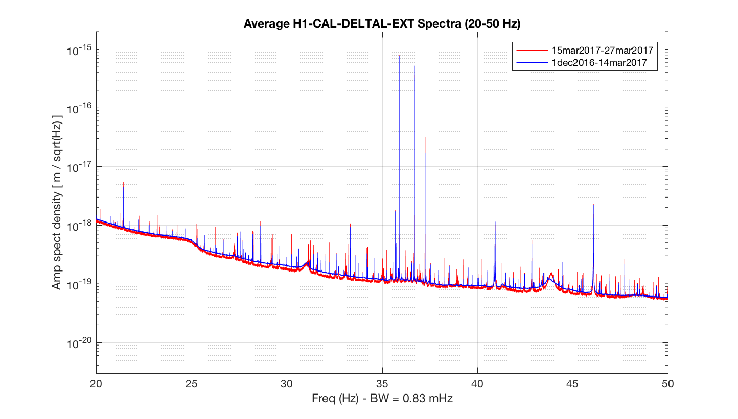
We didn't change any configuration of the HWS camera that day. All HWS cameras have been turned on since the beginning of O2 and have been hooked up to the external power supplies (alog30799) since O1. Since then I haven't heard any complains about HWS cameras making noises. HWS cameras ON has been a nominal configuration since the beginning of O2.
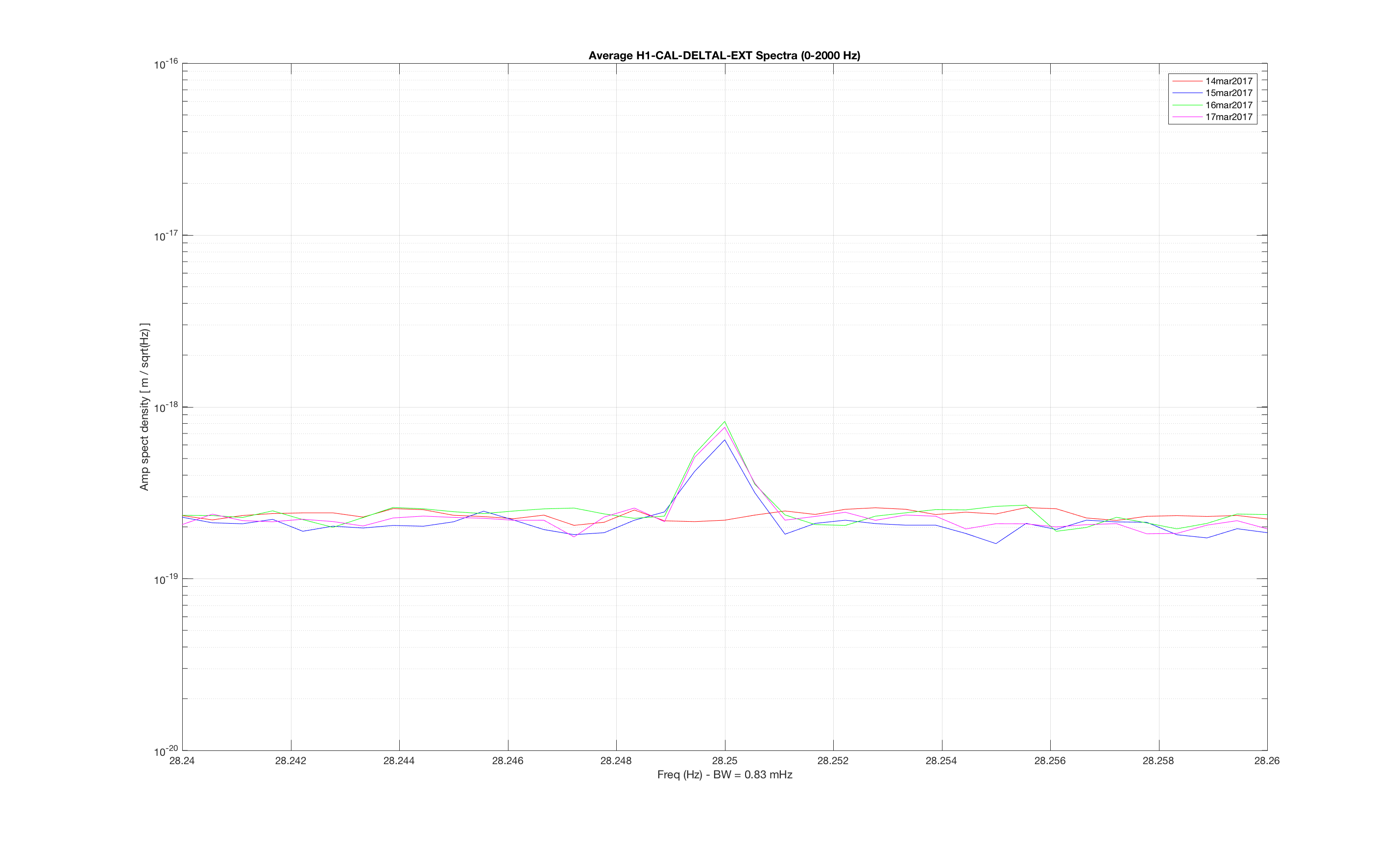
I was asked via e-mail if this problem might have started later in March
with the replacement of the Harmonic Frequency Generator. but explicit
comparisons of daily spectra below show conclusively that the N + 0.25 Hz and
N + 0.75 Hz combs are not present before Tuesday maintenance ("March 14" ends
at 6:00 a.m. CDT on March 14 in the FSCan dating convention), but are present
individually on March 15, 16 and 17. The new  N Hz comb reported above is too weak
to show up well in a single day's measurement with 1800-second SFTs.

I was also told via e-mail (and just saw Nutsinee's note above) that HWS systems
are run routinely during observing mode and that no configuration changes
were made on March 14 (although there are some new cables in place). So perhaps
there is a different culprit among the March 14 activities.

Fig 1: Zoom in of line at 28.25 Hz
Fig 2: Zoom in of line at 38.25 Hz
Fig 3: Zoom in of line at 88.75 Hz
Fig 4: Zoom in of line at 98.75 Hz
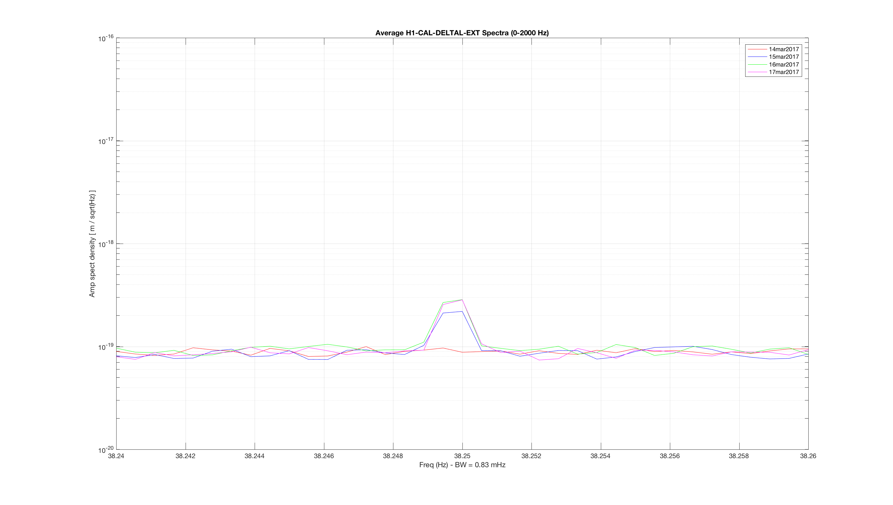
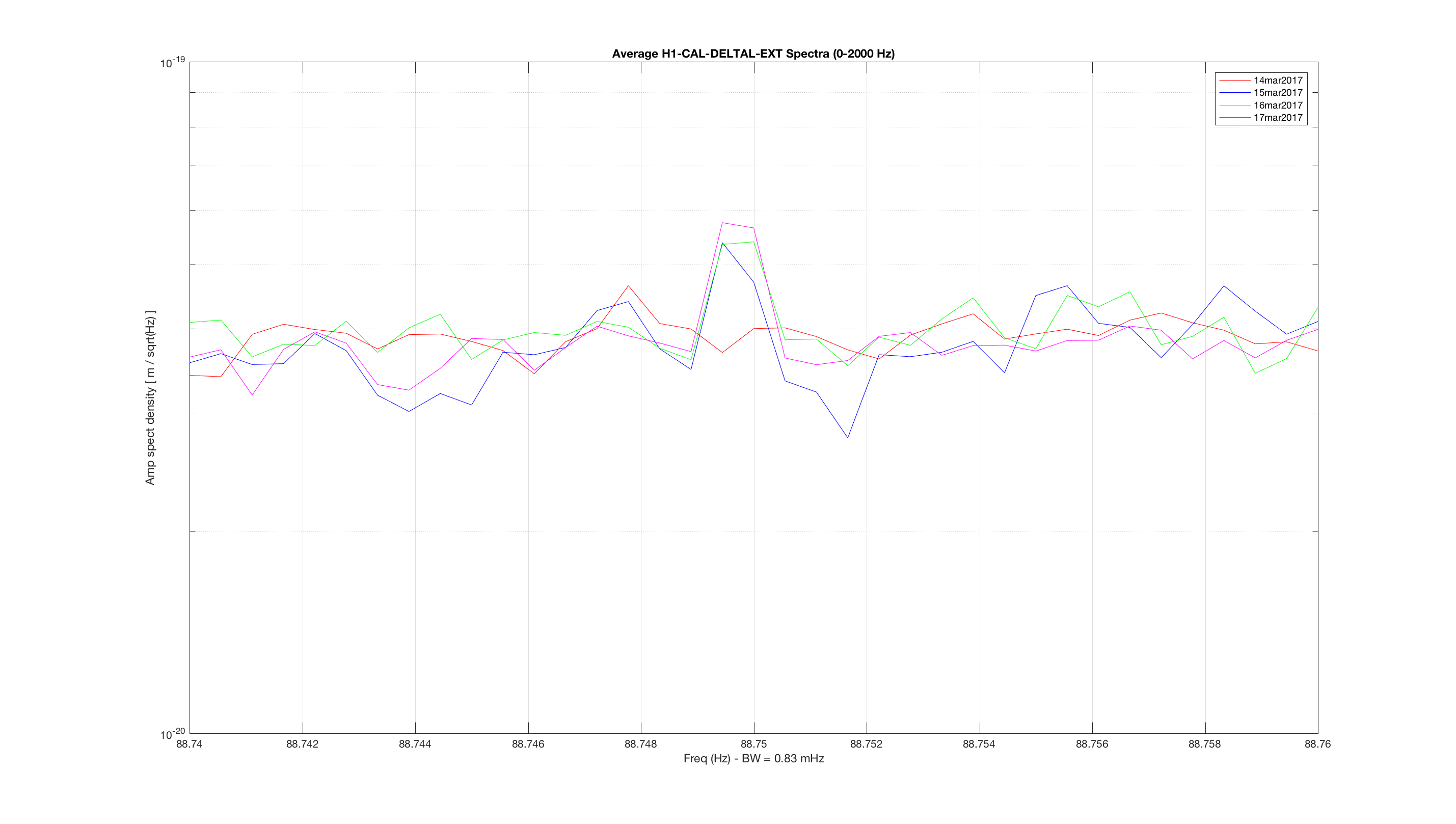
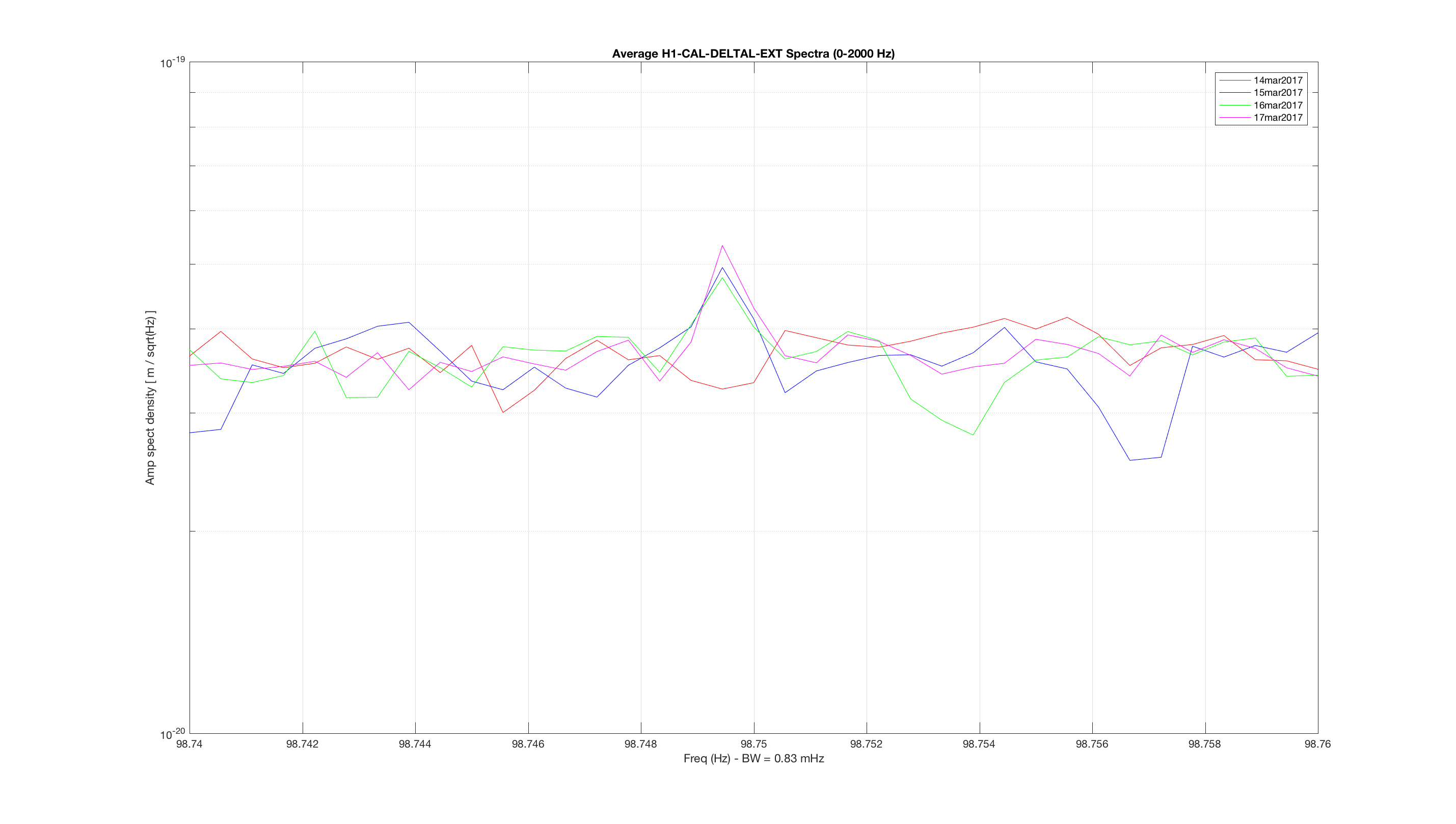
Looking back at the aLOGs from the March 14th period, some possibilities of activities that may be related stick out: 1) PSL bullseye detector for jitter studies installed 2) ITMY OpLev power supply moved 3) New cables for GigE and camera installed 4) ETM OpLevs laser power increased 5) CPS electronics power cycled and board reseated on WBSC1 ITMY 6) DBB powered up and supposedly powered off;is it still on??Kiwamu says he is 99% sure the DBB is off
It looks like all three combs jump in magnetometers at EX and EY between 3/14 and 3/15, but don't have any notable presence in the CS magnetometers.
More clues: at EX, there was a recent change point in the combs (strength drop) between 2/28 and 3/1. At EY, there was one (also a strength drop) between 3/7 and 3/8. These are Fscan dates, covering 24 hours back from the morning when they were run-- in any case, it looks like two prior Tuesdays may be involved.
As a side note, the 1 Hz comb with 0.5 Hz offset mirrors the stated behavior in several channels, at least one magnetometer at EX and one at EY.
Read below for more details on the methodology and the results.
At this point I have 5548 times identified as blip glitches, and the value of the suspension channels for each of those. And 5548 more times that are clean data, with the value of the suspension channels for each of those.
Here's an example plot of the result. I picked one of the most interesting channel (SUS-ETMX_M0_DAMP_Y_INMON). The PDF files attached below contains the same kind of histograms for all channels, divided by test mass.
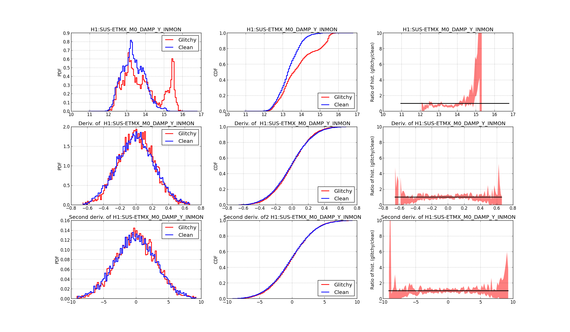 The first row shows results for the SUS-ETMX_M0_DAMP_Y_INMON signal. The first panel compares the histogram of the values of this signal for blip times (red) and clean times (blue). This histogram is normalized such that the value of the curve is the empirical probability distribution of having a particular value of the signal when a blip happens (o doesn't happen). The second panel in the first row is the cumulative probability distribution (the integral of the histogram): the value at an abscissa x gives the probability of having a value of the signal lower than x. It is a standard way to smooth out the histogram, and it is often used as a test for the equality of two empirical distributions (the Kolmogorov-Smirnov test). The third panel is the ratio of the histogram of glitchy times over the histogram of clean times: if the two distributions are equal, it should be one. The shaded region is the 95% confidence interval, computed assuming that the number of counts in each bin of the histogram is a naive Poisson distribution. This is probably not a good assumption, but the best I could come up with.
The second row is the same, but this time I'm considering the derivative of the signal. The third row is for the second derivative. I don't see much of interest in the derivative plots of any signal. Probably it's due to the high frequency content of those signals, I should try to apply a low pass filter. On my to-do list.
However, looking a the histogram comparison on the very first panel, it's clear that the two distributions are different: a subset of blip glitches happen when the signal SUS-ETMX_M0_DAMP_Y_INMON has a value of about 15.5. There are almost no counts of clean data for this value. I think this is a quite strong correlation.
You can look at all the signals in the PDF files. Here's a summary of the most relevant findings. I'm listing all the signals that show a significant peak of blip glitches, as above, and the corresponding value:
| ETMX | ETMY | ITMX | ITMY | |
|---|---|---|---|---|
| L1_WIT_LMON | -21.5 | -54.5 | ||
| L1_WIT_PMON | 495, 498 | 609 | 581 | |
| L1_WIT_YMON | 753 | -455 | 643, 647 | 500.5 |
| L2_WIT_LMON | 437, 437.5 | -24 | -34.3 | |
| L2_WIT_PMON | 1495 | -993, -987 | ||
| L2_WIT_YMON | -170, -168, -167.5 | 69 | ||
| L3_OPLEV_PIT_OUT16 | -13, -3 | 7 | ||
| L3_OPLEV_YAW_OUT16 | -4.5 | 7.5 | -10, -2 | 3 |
| M0_DAMP_L_INMON | 36.6 | 14.7 | 26.5, 26.9 | |
| M0_DAMP_P_INMON | -120 | 363 | 965, 975 | |
| M0_DAMP_R_INMON | 32.8 | -4.5 | 190 | -90 |
| M0_DAMP_T_INMON | 18.3 | 10.2 | 20.6 | 27.3 |
| M0_DAMP_V_INMON | -56.5 | 65 | -25 | -60 |
| M0_DAMP_Y_INMON | 15.5 | -71.5 | -19, -17 | 85 |
Some of the peaks listed above are quite narrow, some are wider. It looks like ITMY is the suspension with more peaks, and probably the most significant correlations. But that's not very conclusive.
There were some days with extremely high rates of glitches in January. It's possible that clumping of glitches in time could be throwing off the results. Maybe you could try considering December, January, and February as separate sets and see if the results only hold at certain times.

Also, it would be nice to see how specifically you can predict the glitches in time. Could you take the glitch times, randomly offset each one according to some distribution, and use that as the 'clean' times? That way, they would have roughly the same time distribution as the glitches, so you shouldn't be very affected by changes in IFO alignment. And you can see if the blips can be predicted within a few seconds or within a minute.
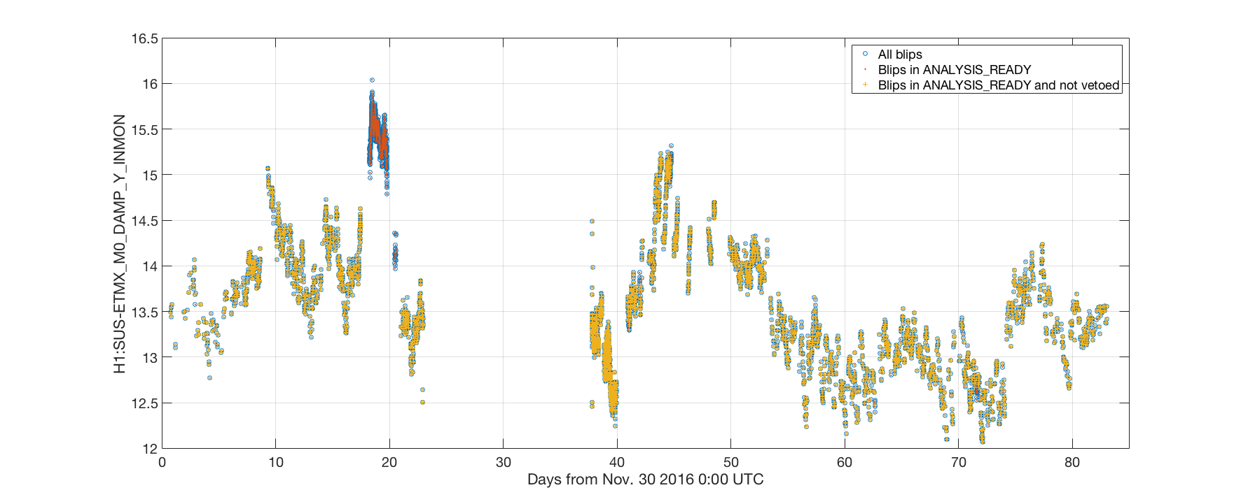
In my analysis I assumed that the list of blip glitches were not affected by the vetoes. I was wrong.
Looking at the histogram in my entry, there is a set of glitches that happen when H1:SUS-ETMX_M0_DAMP_Y_INMON > 15.5. So I plotted the value of this channel as a function of time for all blip glitches. In the plot below the blue circles are all the blips, the orange dots all the blips that passes ANALYSIS_READY, and the yellow crosses all the blips that passes the vetoes. Clearly, the period of time when the signal was > 15.5 is completely vetoed.
So that's why I got different distributions: my sampling of clean times did include the vetoes, while the blip list did not. I ran again the analysis including only non vetoed blips, and that family of blips disappeared. There are still some differences in the histograms that might be interesting to investigate. See the attached PDF files for the new results.
One more thing to check is the distribution over time of the blip glitches and of the clean times. There is an excess of blips between days 39 and 40, while the distribution of clean data is more uniform. This is another possible source of issues in my analsysis. To be checked.
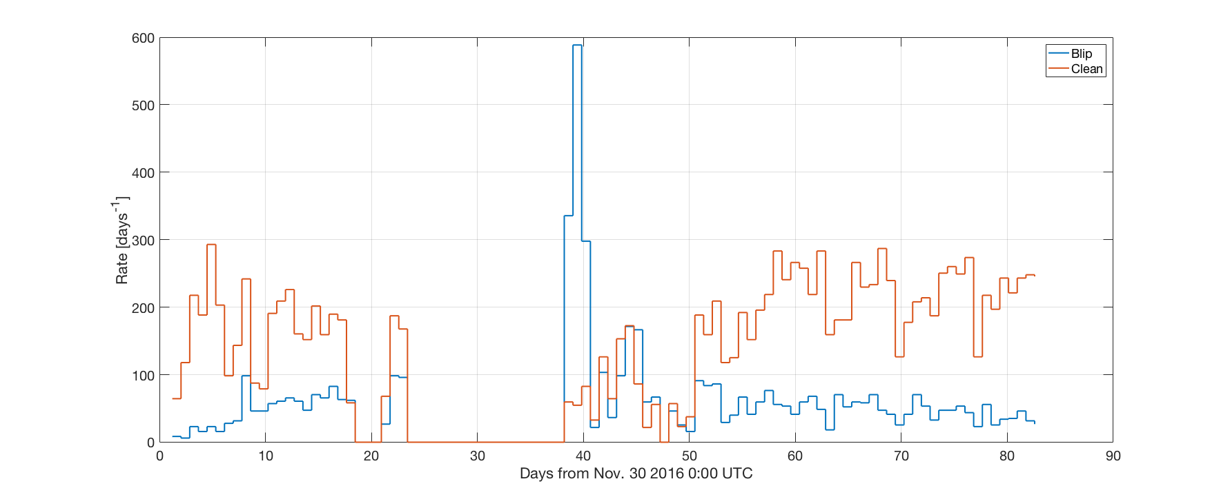
@Gabriele
The excess of blips around day 40 corresponds to a known period of high glitchiness, I believe it was around Dec 18-20. I also got that peak when I made a histogram of the lists of blip glitches coming from the online blip glitch hunter (the histogram is at https://ldas-jobs.ligo.caltech.edu/~miriam.cabero/tst.png, is not as pretty as yours, I just made it last week very quickly to get a preliminary view of variations in the range of blips during O2 so far).

