thomas.shaffer@LIGO.ORG - posted 14:30, Tuesday 28 March 2017 - last comment - 18:12, Tuesday 28 March 2017(35153)
Added new HIG_FREQ_LINES PCal node
Sudarshan, Shaffer
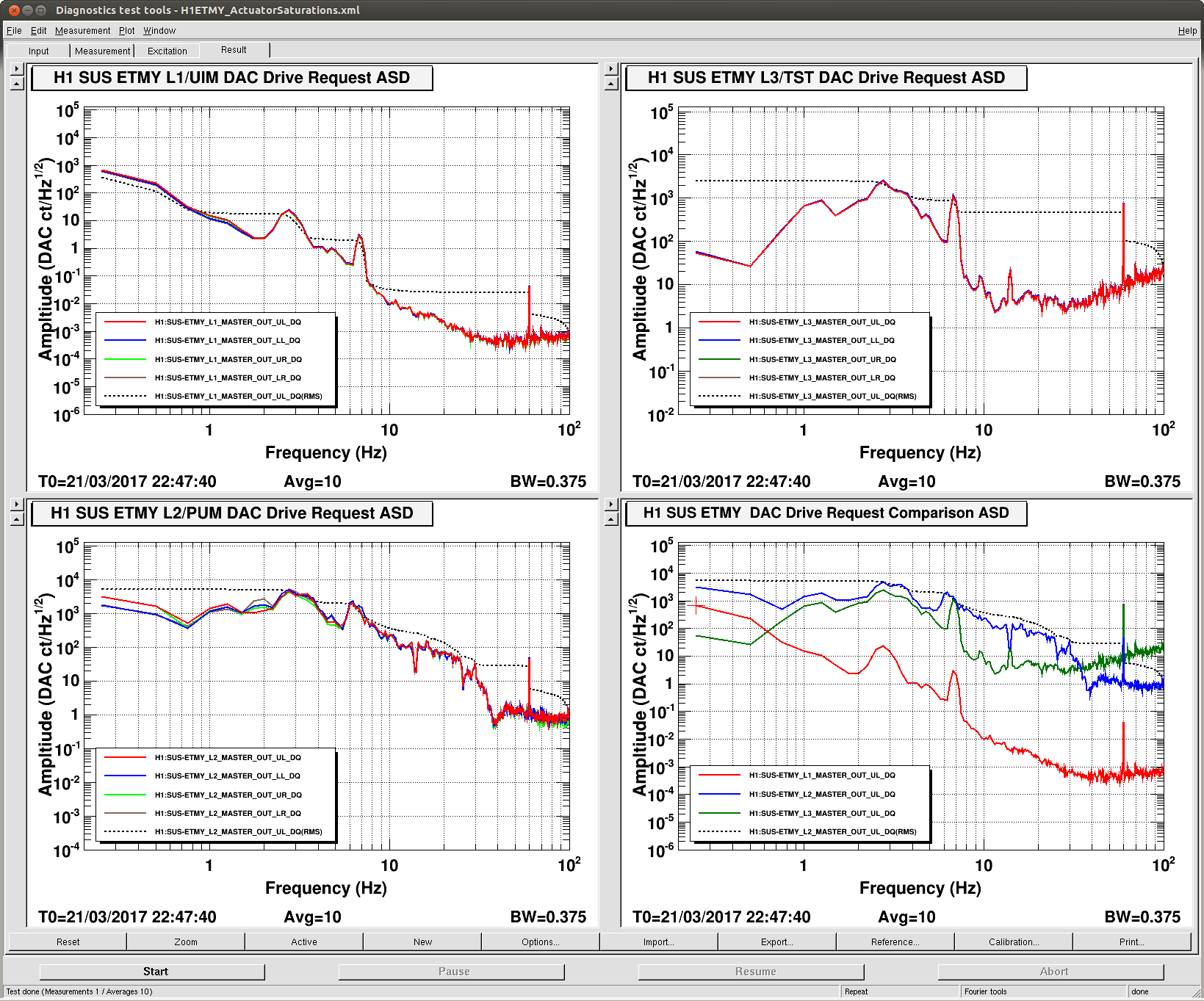
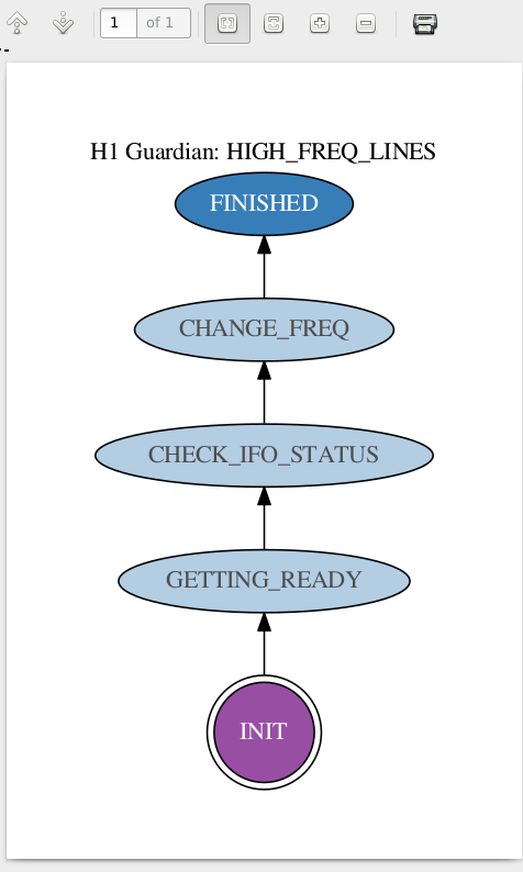
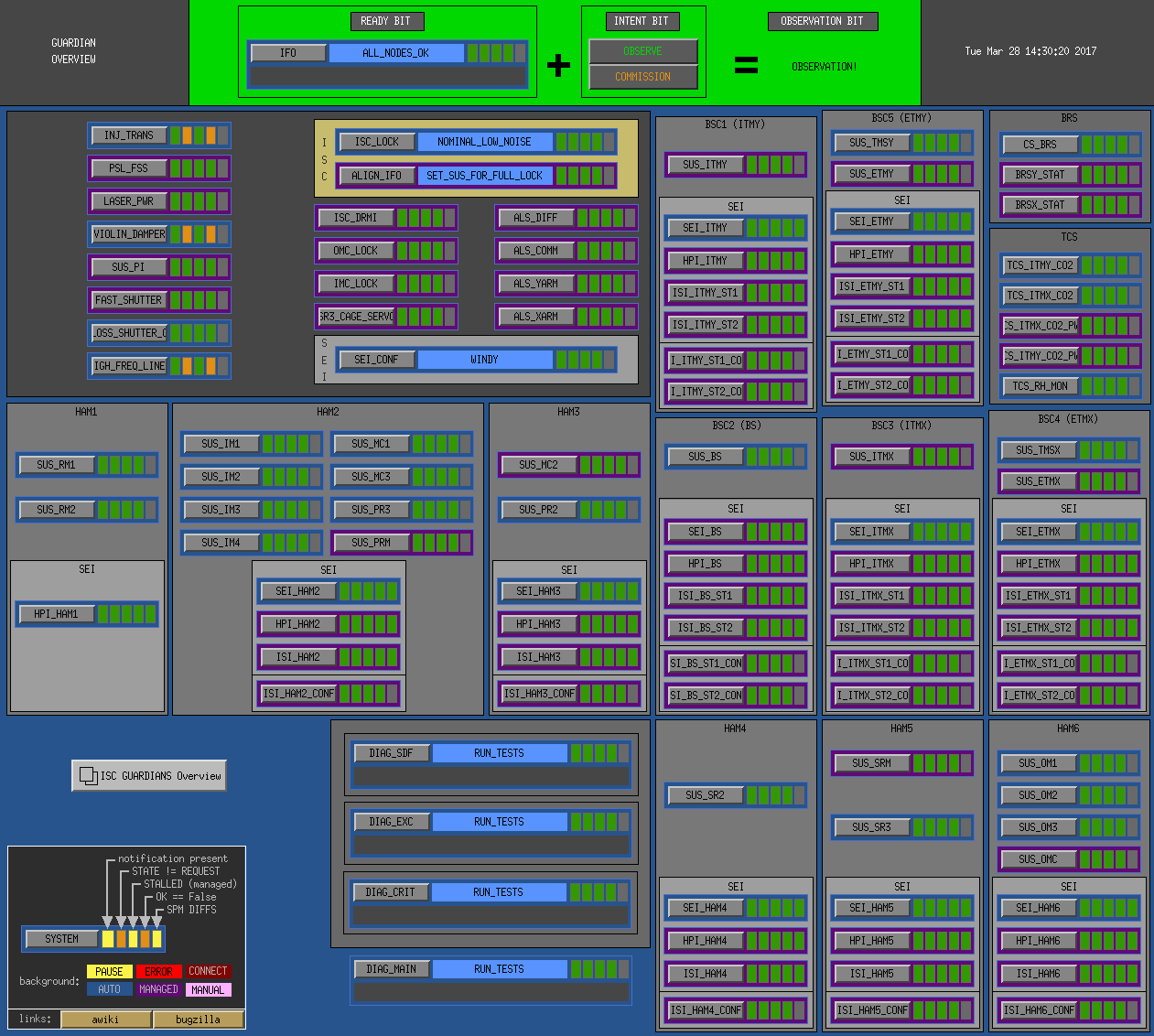
Today I created, started, and tested a node that Sudarshan made to change some EX PCal lines every 24hrs while we are not locked. The code will wait for the gps time to get greater than a day since its last change, then it will wait till the IFO is not locked, and finally it will adjust the frequency by 500hz and jump to waiting for a day to go by. Once the frequency has reached 5100hz it will then hang our in the FINISHED state. Here, Sudarshan can let us know what he wants to do with it.
Attached are the graph for the node and the Guardian overview
Images attached to this report
Comments related to this report
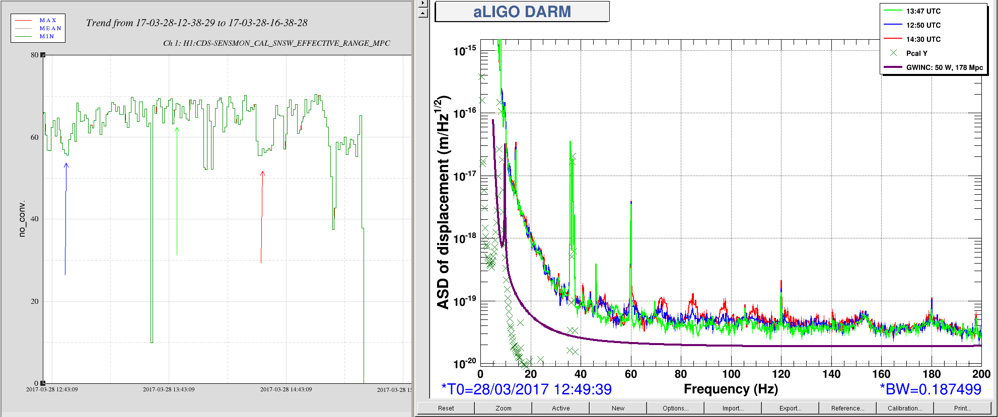
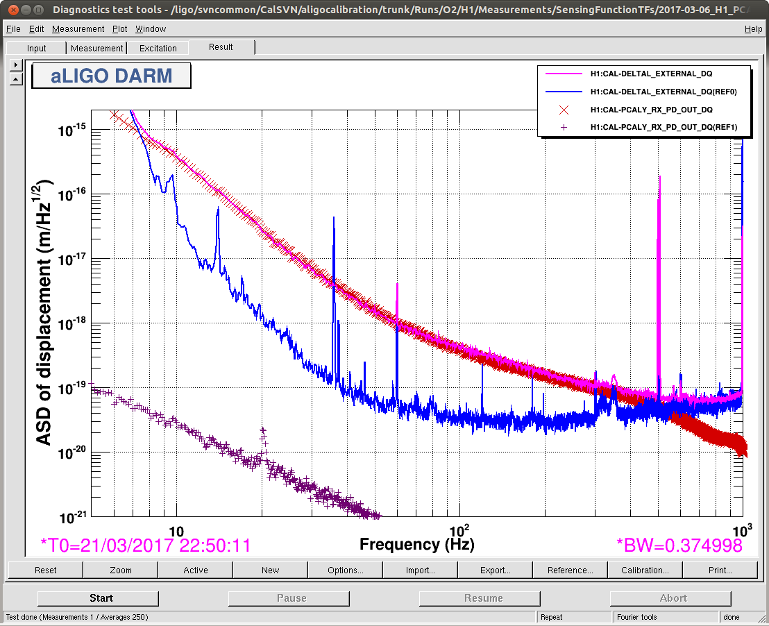
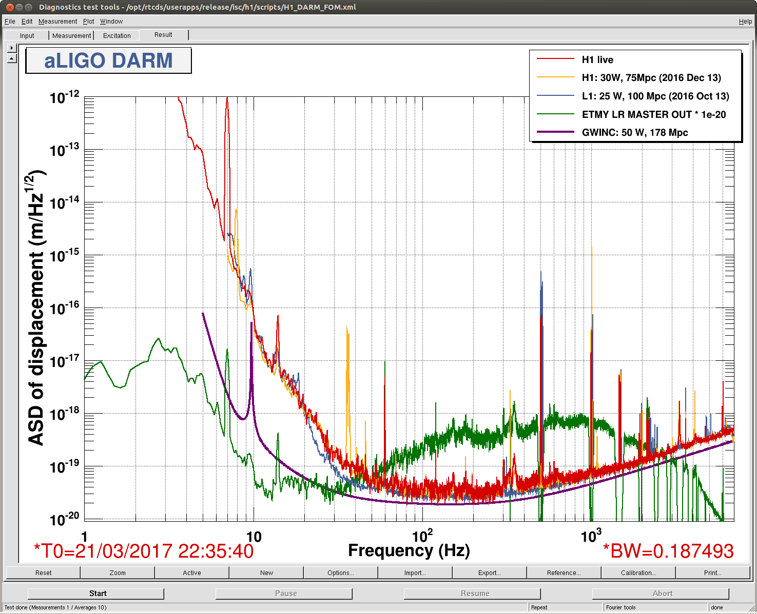
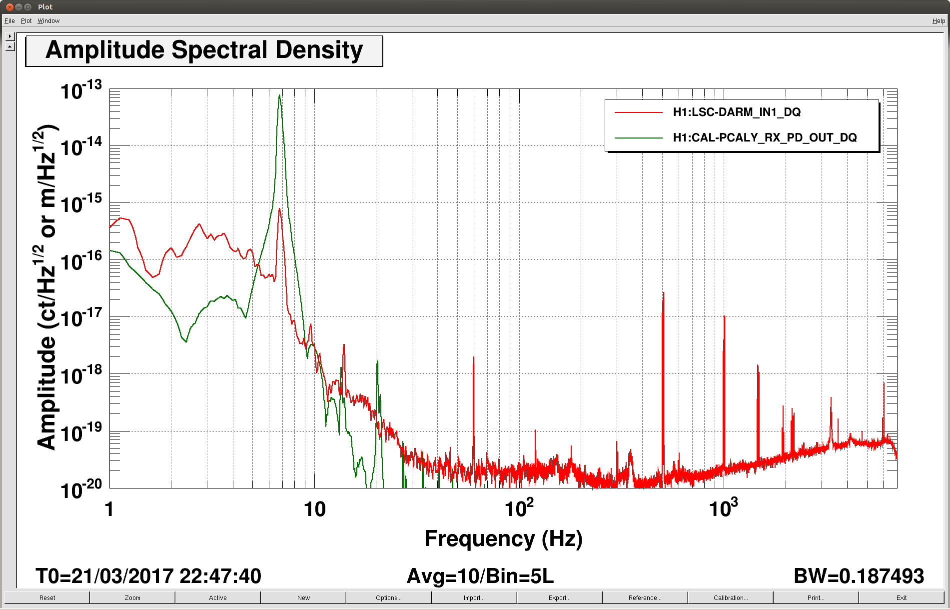
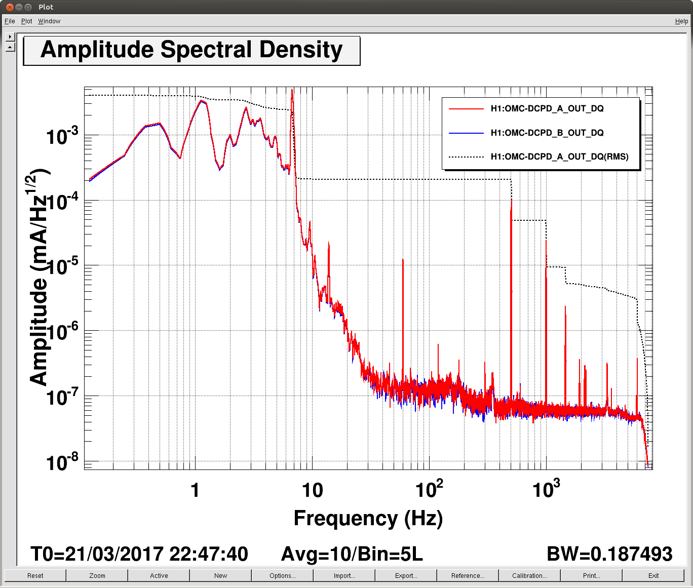
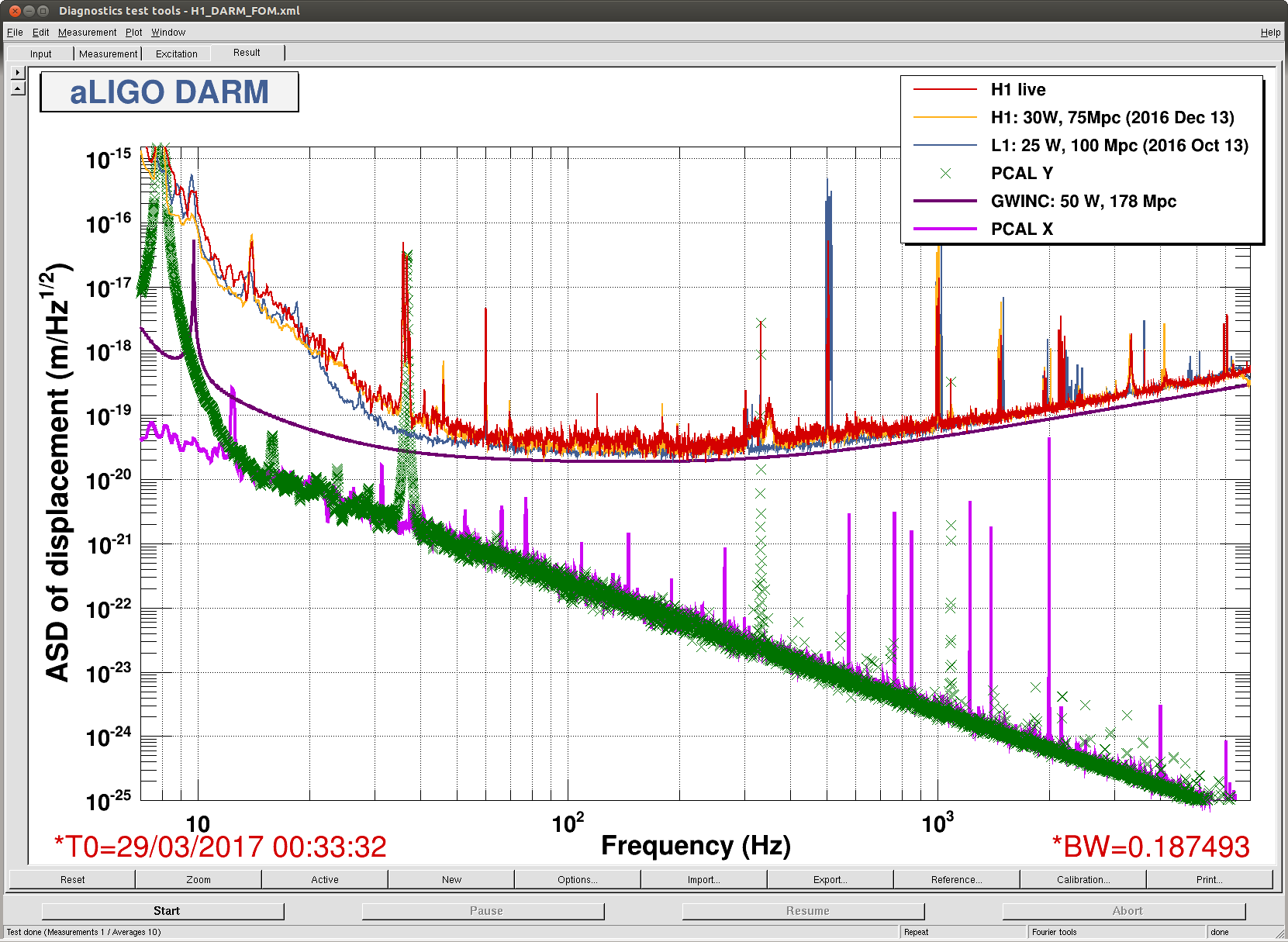
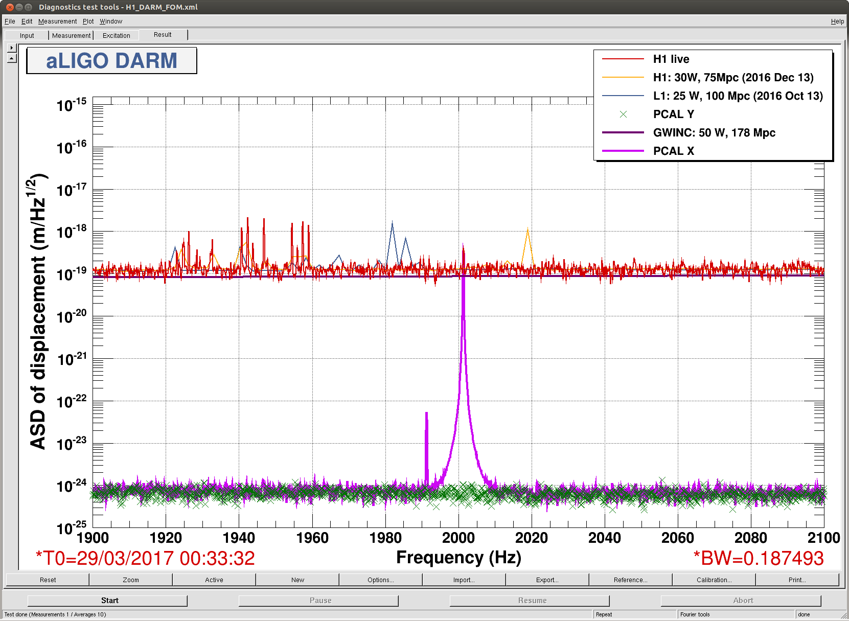
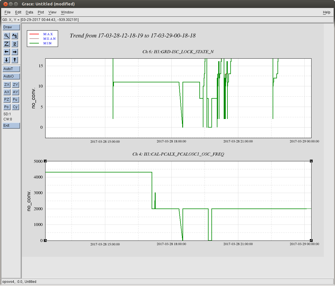
Just a few points of verification, clarification, and tagging DetChar, letting them (especially the CW group) know this sweeping PCAL X calibration line has been turned on.

I attach a full and zoomed CAL-DELTAL spectrum against a PCALX spectrum (among the other usual things from the front wall's sensitivity FOM).

Note that Pulsar injections are on-going, and it doesn't look like these features will interfere. This calibration line regime is sticking to the 2000 to 5000 Hz regions, and pulsar injections only go up to 1991.2 Hz (For a reminder of the full list of pulsar injection frequencies, see LHO aLOG 27642.

The starting frequency is 2001.3 Hz, and the starting excitation amplitude is 30000 [ct], and has been hard-coded to remain this amplitude for all frequencies. The excitation frequency can be tracked using EPICs via this channel:
    H1:CAL-PCALX_PCALOSC1_OSC_FREQ
and you can see a fast-channel version of the requested output here:
    H1:CAL-PCALX_EXC_SUM_DQ

The guardian code for this node lives here
/opt/rtcds/userapps/release/cal/h1/guardian/HIGH_FREQ_LINES.py

and is attached for ease of reference.

After some initial debugging, it guardian's log suggests that TJ left the frequency at 2001.3 starting at 2017-03-28 17:16:31 UTC, though it looks like the frequency has only been stable at 2001.3 since 19:49:00 UTC. TJ has the CHECK_IFO_STATUS state look whether the ISC_LOCK guardian's state is lower than 11,
which means the excitation is killed if we're in
    - INITIAL ALIGNMENT
    - DOWN
    - IDLE
    - LOCKLOSS
    - LOCKLOSS_DRMI
    - INIT
but maybe we want to rethink this, because it seems to turn off the excitation at unnecessary times (see attached dataviewer trend, where the guardian has changed the frequency twice since TJ left it).
Images attached to this comment
Non-image files attached to this comment