TITLE: 03/28 Day Shift: 15:00-23:00 UTC (08:00-16:00 PST), all times posted in UTC
STATE of H1: Lock Acquisition
INCOMING OPERATOR: Nutsinee
SHIFT SUMMARY:
- Roto-Rooter fixing leak at VPW
- FD testing all Alarm and Detector systems
- Apollo working at MY
- Bailing still going on as of 19:08UTC. Workers are ≈500m from the end station and working back towards the corner. Anthropogenic and wind graph is up to ≈1µm/s
LOG:
15:06 Intention bit set to "Preventative Maintenance"
15:07 Peter and Jeff B to PSL enclosure
15:08 Fire Dept. on site smoke/heat testing
15:15 Hugh to EX
15:35 Travis to EX for PCAL work
15:50 Fil to EX for Interlock cabling.
15:53 Christina and Karen to out buildings
15:55 Gerardo to mid-stations
16:00 NORCO LN2 Y-ARM
16:13 Jeff B going to End Stations for FAMIS dust monitor checks
16:13 Hugh back from EX?
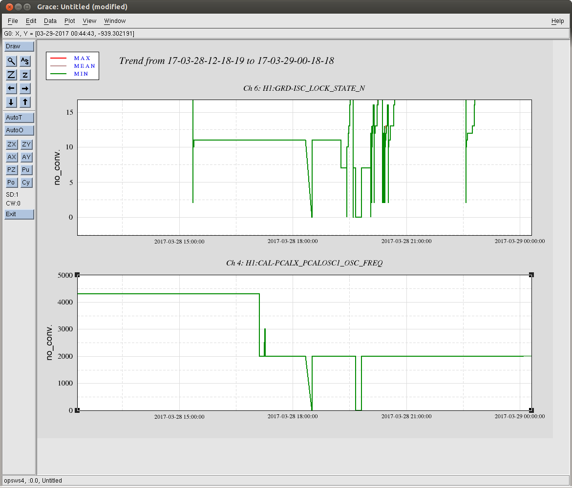
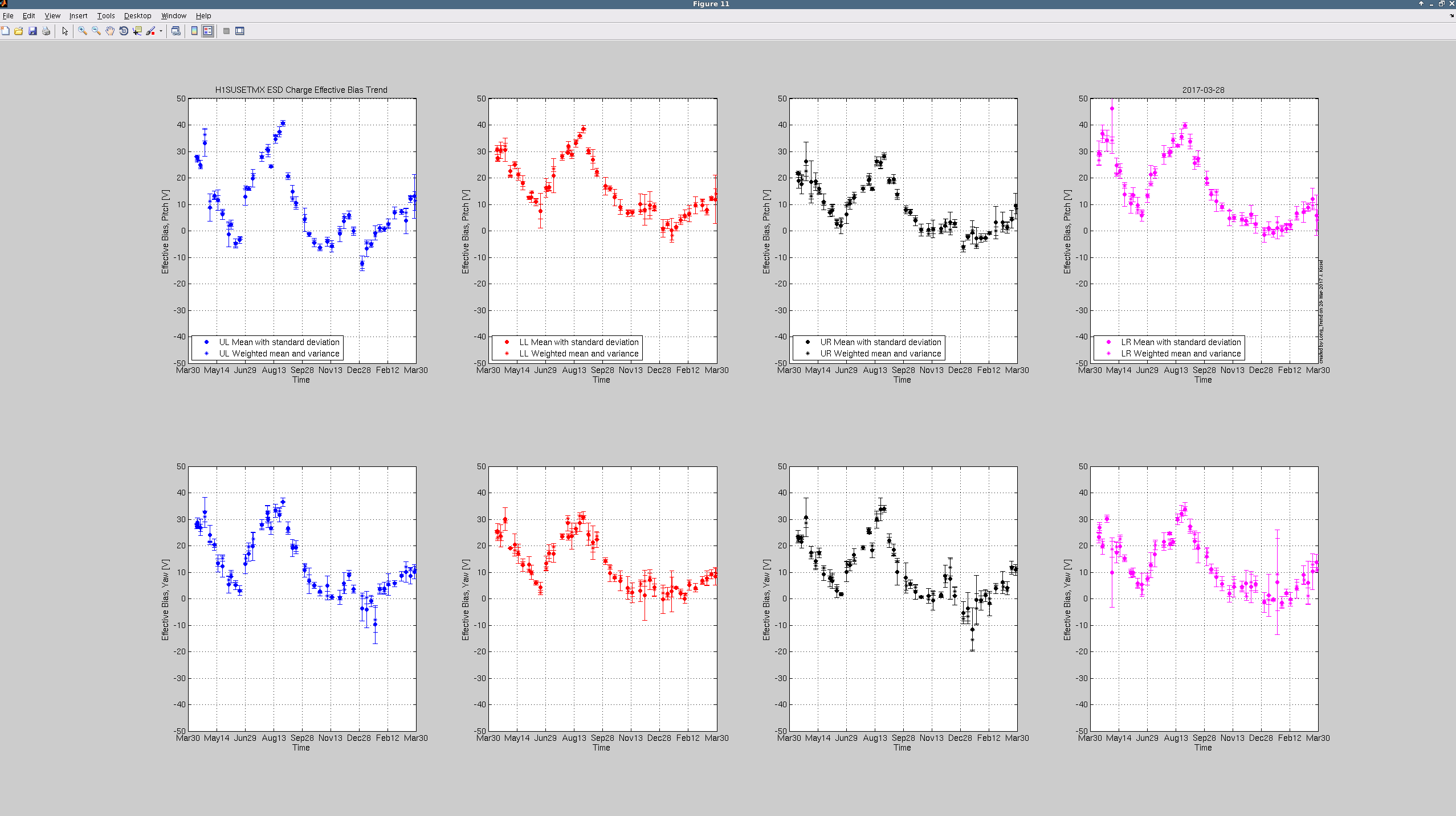
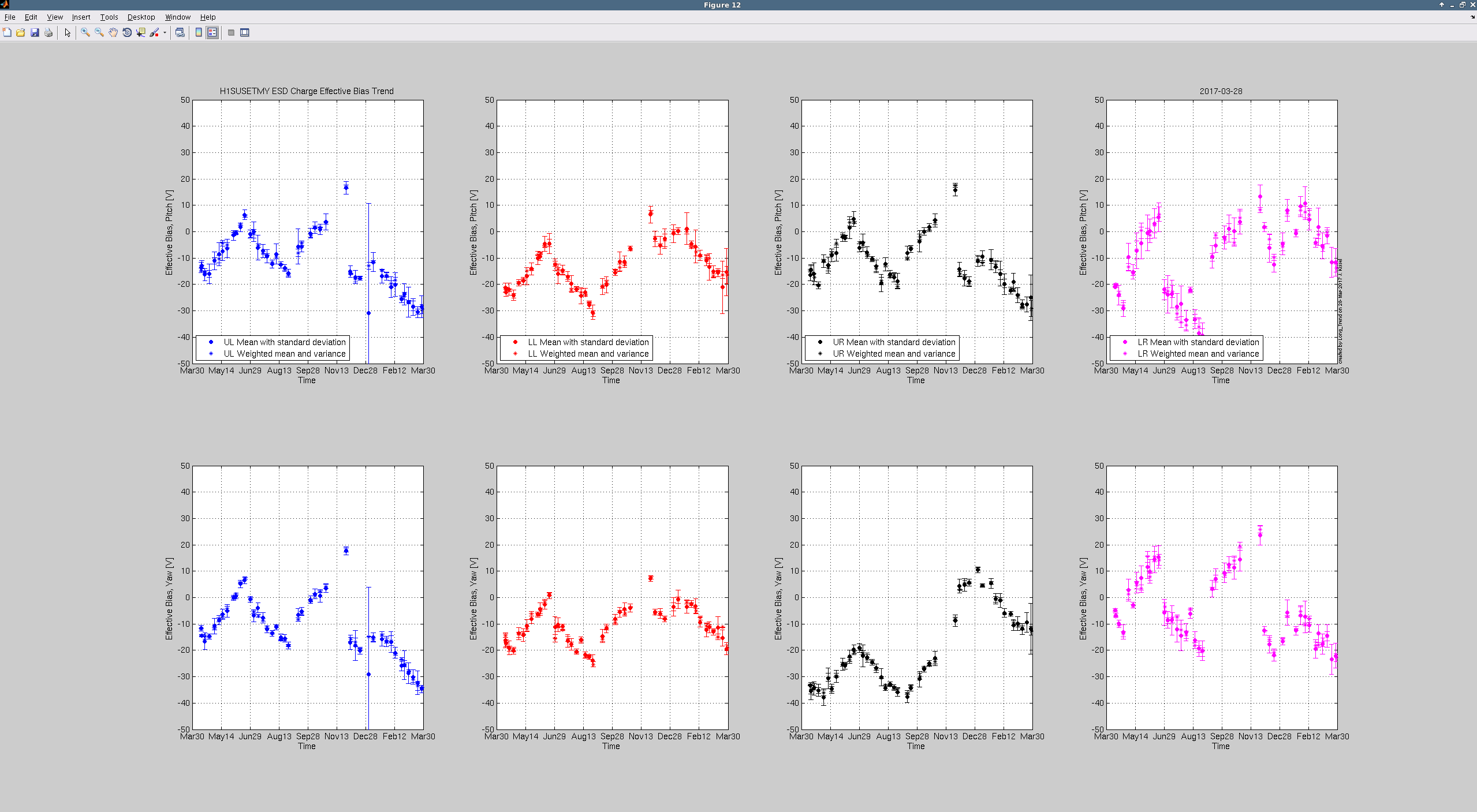
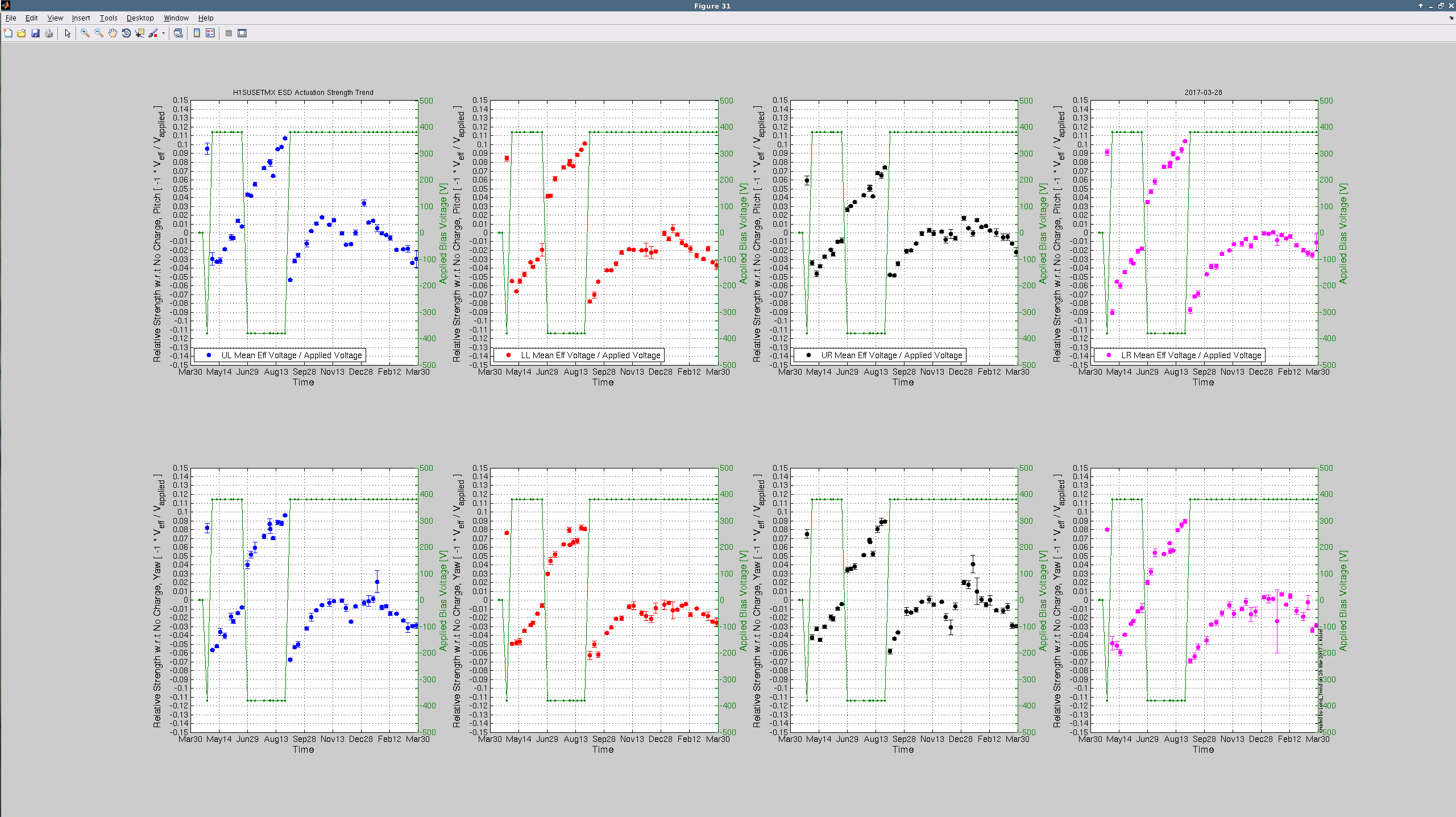
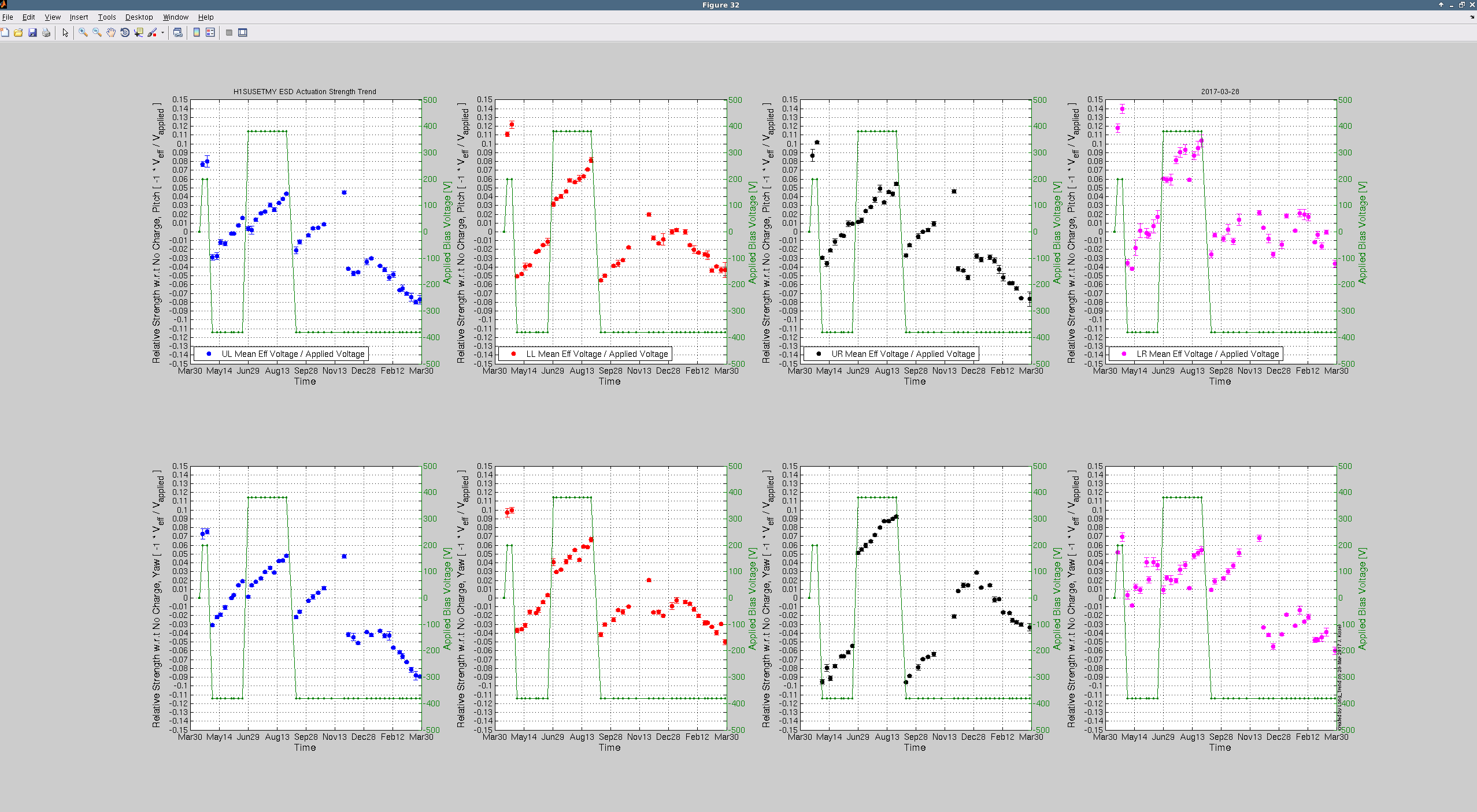
16:31 TJ doing Charge measurements on ETMY
16:34 More FD personell on site
16:40 Taking FD to CER
16:43 NORCO LN2 X-ARM
16:45 More fire personnell on site
16:45 Betsy to LVEA for parts. HWS work is postponed.
17:04 Travis back from EX
17:05 Karen leaviong EY
17:09 Jeff B back
17:14 Carlos out to EX to retrieve HWS card
17:31 Bubba bringing FD into LVEA
17:44 Dick into LVEA - non invasive
17:44 Carlos reported back from EX
17:53 Fire testing in OSB is done
17:54 Hugh into CER
18:00 Bubba out of LVEA with FD
18:28 DAQ restart
18:38 Paradise Water on site for delivery
19:06 FIll back
19:07 Bailing still going on
21:31 Betsy, Travis and TJ to MX
22:34 Lockloss - yet undetermined but possibly linked to some BRS issue that Hugh was doing. He and Jeff K are hashing it out.
22:41 Switched ISI_CONFIG back to NOBRSY and recovered ETMY ISI to resume.
22:49 TJ, Betsy, and Travis back
23:00 Handing of to Nutsinee